1
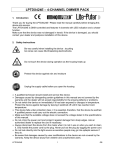
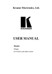
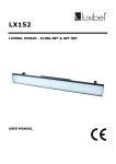
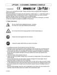
LPTDX1220 – 12-CHANNEL DIMMER PACK
1. Introduction
To all residents of the European Union
Important environmental information about this product
This symbol on the device or the package indicates that disposal of the device after its lifecycle could harm the environment.
Do not dispose of the unit (or batteries) as unsorted municipal waste; it should be taken to a specialised company for recycling.
This device should be returned to your distributor or to a local recycling service.
Respect the local environmental rules.
If in doubt, contact your local waste disposal authorities.
Thank you for buying the LPTDX1220 ! Please read the manual carefully before bringing this
device into service.
Maintenance is easy and the LPTDX1220 features 12 DMX channels, dimming and switching
modes, modular construction 12 x 20A in 3 phase systems, analogue or DMX control and 0-10V
or DMX input.
Make sure that the device was not damaged in transit. If the device is damaged, you should
contact your dealer and postpone installation of this device.
2. Safety Instructions
Be very careful when installing the device : touching
live wires can cause life-threatening electroshocks.
Do not touch the device during operation as the housing heats up
Protect this device against rain and moisture
Unplug the supply cable before opening the housing
• A qualified technician should install and service this device.
• Damage caused by disregarding certain guidelines in this manual is not covered by the
warranty and the dealer will not accept responsibility for the ensuing defects or problems.
• Do not switch the device on immediately if it has been exposed to changes in temperature.
Protect the device against damage by leaving it switched off until it has reached room
temperature.
• This device falls under protection class I. It is essential, therefore, that the device be earthed.
A qualified person must carry out the electric connection.
• Make sure that the available voltage does not exceed the voltage stated in the specifications.
LPTDX1220
1
GB
• Do not crimp the power cord and protect it against damage from sharp edges. Ask an
authorised dealer to replace the cord if necessary.
• Always disconnect the device from the mains when it is not in use or when you wish to clean
it. Only handle the power cord by the plug. Never pull out the plug by tugging the power cord.
• Do not look directly into the light source as sensitive people may go into epileptic seizure if
they do.
• Note that damage caused by user modifications to the device is not covered by the warranty.
Keep the device away from children and unauthorised users.
3. General Guidelines
• This device is a lighting controller for professional use on stage, in discos, theatres, etc. The
LPTDX1220 should only be used indoors with an alternating current of max. 230Vac/50Hz.
• Do not shake the device. Avoid brute force when installing or operating the device.
• Select a location where the device will be protected against extreme heat, moisture and dust.
• Do not use or transport the device under temperatures < 5°C or > 35°C.
• Familiarise yourself with the functions of the device before actually using it. Do not permit
operation by unqualified people. Any damage that may occur, will probably be due to
unprofessional use of the device.
• Use the original packaging if the device is to be transported.
• Note that all modifications of the device are forbidden for safety reasons.
• Do not remove the serial number sticker from the device as doing so will void the warranty.
Only use the device for its intended purpose. All other uses may lead to short-circuits, burns,
electroshocks, lamp explosion, crash, etc. Using the device in an unauthorised way will void
the warranty.
4. Installation
Mount the device in your rack. Connect the spots or light effects to the screw connectors at the
back of the device (see figure below : 21-28). Connect your DMX controller to the DMX IN
socket with a 5-pole DMX cable. Connect the second device to the DMX OUT of the first device
when connecting several LPTDX1220's to your DMX controller.
The device will always power on in the mode it was last used.
LPTDX1220
2
GB
5. Description
a) Front
b) Channel Module
1) Locking / unlocking system
2) TRIG LED indicator
3) AC LED indicator
4) 20A automatic fuse
5) Ventilation holes
c) DMX interface
6) LED indicators for mains phase
7) LED indicator for DMX input
8) LED display
9) ← key
10) ↑ key
11) → key
12) CANCEL key
13) SELECT key
LPTDX1220
3
GB
14)
15)
16)
17)
18)
19)
20)
↓ key
SET key
FUNCTION key
MODE key
5-pin DMX output socket (see detail below)
5-pin DMX input socket (see detail below)
Analogue input socket : 0-10V (see detail below)
Pin 1 – 12
Pin 13
Pin 14
Pin 15
21)
22)
23)
24)
:
:
:
:
CH1 – CH12
not connected
+12V
earth
Pin 1 : earth
Pin 2 : data (-)
Pin 3 : data (+)
Pin 4 : not connected
Pin 5 : not connected
earth connection
neutral wire
positive wire
earth connection
LPTDX1220
25)
26)
27)
28)
4
mains power wire #1
mains power wire #2
mains power wire #3
neutral wire
GB
6. Operating Instructions
Upon activation, the device will be in the last mode it was functioning before power off. Press
the MODE button to select the next mode and the LED display will show the chosen mode. A
selected but unconfirmed mode will have dots between the letters on the display. Press the SEL
button to confirm the selected mode.
MODE 1 : DMX
MODE 2 : ANALOGUE
MODE 3 : OFF
Functions and Settings
After selecting the desired mode, select the desired function by pressing FUN and different
settings by pressing SET. Again, dots between the letters on the display indicate a temporary
setting.
FUNCTION 1 : MONITOR
FUNCTION 2 : TEST
FUNCTION 3 : AUTOMATIC FADER TEST
LPTDX1220
5
GB
SETTING 1 : PREHEATING
SETTING 2 : DIMMED / SWITCHED
SETTING 3 : SCENE PROGRAMMING
SETTING 4 : SET FADER TIME
SETTING 5 : LIST OF FADER TIMES
SETTING 6 : SET SQUARE LAW OR LINEAR DIMMING CURVE
SETTING 7 : SETTING MAXIMUM OUTPUT WATTAGE
Locking the keyboard : Press MODE + FUN + ↓ simultaneously
Unlocking the keyboard : Press MODE + FUN + ↑ simultaneously
Three Different Modes
Mode 1 : DMX
The display reads :
d = DMX
001 – 512 = DMX start addresses
←
→
↑
↓
SEL
SET
CAN
MODE
:
:
:
:
:
:
:
:
decrease the DMX start address of a channel
increase the DMX start address of a channel
increase the DMX start address by 12
reset to d001
confirms the selected channel
access to different settings
cancels current operation and return to the previous confirmed one
switch to analogue mode
Assign a start address to each LPTDX1220 when connecting multiple LPTDX1220’s to a DMX
control panel. This address determines the channels used by each LPTDX1220.
Example :
Device #1 : start address = d001, DMX channels used : 01 - 12
Device #2 : start address = d013, DMX channels used : 13 - 24
Device #3 : start address = d025, DMX channels used : 25 - 36
A resistor should terminate the DMX connection. Put the ON/TERMINATE selector in the ON
position.
Mode 2 : Analogue
The display reads :
LPTDX1220
6
GB
SEL
: Confirms analogue mode
CAN : Cancels the current operation and returns to the last confirmed operation
MODE : Change to OFF mode
Mode 3 : OFF
The display reads :
SEL
: Confirms OFF mode
CAN : Cancels the current operation and returns to the last confirmed operation
MODE : Change to DMX mode
Three Different Functions
Function 1 : Monitor
The display reads :
01 – 12 = channels
0.0 – 9.9 = settings of a channel
Settings can be done per channel automatically or manually.
Automatic setting : the display shows the settings of each channel.
Manual setting
: to select channels separately. Can be used to change channels while in
chaser mode.
←
→
SET
CAN
MODE
FUN
:
:
:
:
:
:
decrease by one channel
increase by one channel
switch to different settings
cancels current operation and returns to the previous confirmed one
change to analogue mode
change to TEST function
Function 2 : TEST
The display reads :
LPTDX1220
7
GB
tA = test all channels
01 – 12 = channels
.00 - .99 = level per channel
←
→
↑
↓
SEL
SET
CAN
:
:
:
:
:
:
:
decrease by one channel
increase by one channel
increase the output level of a channel. Starts the test mode.
decrease the output level of a channel. Starts the test mode
the output level of all the channels will be set to the chosen value.
switch to different settings
push once : resets all levels to zero
push twice : cancels current operation and returns to the previous confirmed mode.
MODE : switch back to the last confirmed mode
FUN : switch to “automatic fader test”
Function 3 : AUTOMATIC FADER TEST
The display reads :
AF = automatic fader test
01 - 12 = channels
AL = all channels
←
→
↑
↓
SEL
SET
CAN
:
:
:
:
:
:
:
decrease the output level of a channel
increase the output level of a channel
maintains the output level of the channel at 100% as long as the key is pressed
maintains the output level of the channel at 0% as long as the key is pressed
starts the test procedure
switch to different settings
push once : resets all levels to zero
push twice : cancels current operation and returns to the previous confirmed mode.
MODE : switch back to the last confirmed mode
FUN : switch to “monitor function”
Seven Different Settings
Setting 1 : Preheating
The display reads :
AL = all channels
01 – 12 = channels
0.0 – 6.0 = preheating level of the dimmer from 0-6%
LPTDX1220
8
GB
←
→
↑
↓
SET
CAN
MODE
FUN
:
:
:
:
:
:
:
:
decrease one channel
increase one channel
increase the preheating level
decrease the preheating level
change to DIMMED/SWITCHED setting
cancels current operation and returns to the previous confirmed one
switch back to the last confirmed mode
switch to different functions
Setting 2 : Dimmed / Switched
The display reads :
AL = all channels
01 – 12 = channels
d = dimmed
S = switched
- - = combination of “dimmed” and “switched” (only possible when the channels have been set
as “dimmed” or “switched”)
←
→
↑
↓
SET
CAN
MODE
FUN
SEL
:
:
:
:
:
:
:
:
:
decrease one channel
increase one channel
change from dimmed to switched
change from switched to dimmed
change to SCENE PROGRAMMING setting
cancels current operation and returns to the previous confirmed one
switch back to the last confirmed mode
switch to different functions
memorise the setting
Setting 3 : Scene Programming
The display reads :
Six scenes can be stored in the memory.
Press ► : SC = 1 → SC = 2 → SC = 3 → SC = 4 → SC = 5 → SC = 6
Press ◄ : SC = 6 → SC = 5 → SC = 4 → SC = 3 → SC = 2 → SC = 1
Connect the LPTDX1220 with your dimming console (DMX/analogue) or use the self-test
function of the LPTDX1220. Subsequently, you should select SC=0 or SC=1 --- SC=6
LPTDX1220
9
GB
Press SEL to confirm.
SC=0 is executed autoatmically when the device is activated.
Read “Setting 4” below if you want to change the fade-in / fade-out time.
Setting 4 : Setting the Fader Time
Set the fader time (Read “Setting5” below)
1
2
3
4
5
6
7
8
9
A
B
C
=all channels
=1st channel
=2nd channel
=3rd channel
=4th channel
=5th channel
=6th channel
=7th channel
=8th channel
=9th channel
=10th channel
=11th channel
=12th channel
Press ► to increase channels
Press ◄ to decrease channels
Press ▲ to extend the fader time
Press ▼ to shorten the fader time
Press SEL to confirm
LPTDX1220
10
GB
Setting 5 : List of Fader Times
LPTDX1220
11
GB
Setting 6 : Install dimming curve C2 or C3
Dimming curve C2 :
Indicates the linear relationship between the position of the slide control and the output power.
Dimming curve C3 :
More suited for stage lighting. The output power value and the control value (position of the
slide control) are directly proportional, yielding a more flexible control range in case of low
luminous intensity. This is why professionals prefer dimming curve C3.
Press ▲ : change dimming curve
Press ▼ : change dimming curve
Press SEL to confirm
Note that the factory setting is C3.
LIGHT
OUTPUT
DIMMER POSITION %
Our eyes are most sensitive to low luminous intensity, in particular to the range that lies below
25% of maximum luminous intensity (100%). Therefore, using C3 yields a more flexible control
range.
LPTDX1220
12
GB
Setting 7 : Setting the Maximum Output Power Limit
This is the max. output power control (from 50% --- FF% (100%)
1
2
3
4
5
6
7
8
9
A
B
C
=all channels
=1st channel
=2nd channel
=3rd channel
=4th channel
=5th channel
=6th channel
=7th channel
=8th channel
=9th channel
=10th channel
=11th channel
=12th channel
Press ► to increase channels
Press ◄ to decrease channels
Press ▲ to increase the max. output power
Press ▼ to diminish the max. output power
Press SEL to confirm
When a channel is set as a non-dimming channel, it doesn’t have a preheat function and a you
cannot install a max. output power output wattage limit setting function.
The factory setting is FF for all channels, which means “100% output”.
7. Cleaning and Maintenance
1. All screws should be tightened and free of corrosion.
2. The housing, mounting supports and connections should not be modified or tampered with
e.g. do not drill extra holes in mounting supports, do not change the location of the
connections, …
3. The electric power supply cables should be undamaged. Have this device installed by a
qualified technician.
8. Caution
• Disconnect the device from the mains prior to maintenance.
• Use a moist cloth to clean the device and avoid the use of alcohol or solvents for cleaning
purposes.
• Spare parts should be ordered with your local dealer.
LPTDX1220
13
GB
9. Technical Specifications
Power Supply
Number of channels
DMX input & output
Analogue Output
Max. Current
Dimensions
Weight
230Vac/50Hz
12
5-pin XLR socket
15-pin SUB-D
20A per channel
482 x 176 x 260mm
16kg
The information in this manual is subject to change without prior notice.
LPTDX1220
14
GB