1
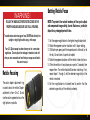
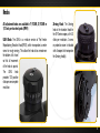
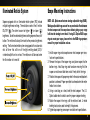
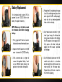
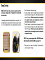
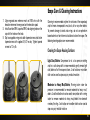
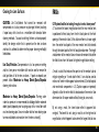
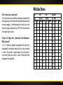
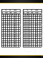
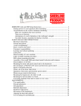
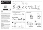
TABLE OF CONTENTS
Thank you for choosing U.S. Optics. The product you have
purchased has been hand assembled to provide superior optical
clarity and durability in any environment. We are confident that
the optic you have chosen will live up to your highest expectations.
This operator’s manual will guide you through the steps to
properly install, zero and maintain your optic for optimal
performance. Should you have questions that have not been
addressed in this manual please contact our Customer Service
Department directly at (714) 582-1956. We will be happy to
assist you.
Make every shot count!
The U.S. Optics Team
1 RETICLE FOCUSING
2 SETTING RETICLE FOCUS
3KNOBS
5 ILLUMINATED RETICLE SYSTEM
6 SCOPE MOUNTING INSTRUCTIONS
7 BATTERY REPLACEMENT
9 SCOPE ZEROING
14 SCOPE CARE AND CLEANING INSTRUCTIONS
16FAQ’s
20 RIFLE DATA SHEETS
23 LIMITED LIFETIME WARRANTY
Your U.S. Optics scope has been factory set for a zero down
angle base. Do not adjust the windage or elevation knob until
after you have mounted and test fired your scope as outlined in
this user’s manual.
Reticle Focusing
The ocular diopter adjustment ring
is used to focus the reticle. Diopter
adjustment is from +2 to -3. Do not
use the ocular eyepiece to focus the
sight picture or parallax.
TIC S, I
To avoid serious vision damage or loss, NEVER look directly into
sunlight or bright lights while using a rifle scope.
NOTE: To prevent the natural tendency of the eye to adjust
and compensate image clarity, do not fixate on a particular
object for a prolonged period of time.
1. Set the scope magnification to the highest magnification level.
2. Rotate the eyepiece counter clockwise until it stops rotating.
3. With both eyes open, point the scope toward a white wall, or to
the sky. Do not stare at a particular object.
4. Rotate the eyepiece clockwise until the reticle is clearly in focus.
5. When the reticle is in focus close your eyes for 3 seconds, then
reopen them. The reticle should still be clear and sharp. If not,
repeat steps 1 through 4 until the desired image clarity of the
reticle is reached.
6. Set the magnification to its lowest level to confirm that the
desired image clarity of the reticle is achieved.
OP
FOLLOW THE MANUFACTURER’S INSTRUCTIONS ON THE
PROPER HANDLING AND SAFE USE OF ALL FIREARMS.
Setting Reticle Focus
S
.
U
.
WARNING!
2
TIC S, I
Knobs
OP
US#4 Knob: The US#4 is a miniature version of The Erector
Repositioning Elevation Knob (EREK), which incorporates a center
screw for rough zeroing. This allows the knob to be zeroed near
the bottom of its travel
so that all movement
of the knob is upward.
The
US#4
knob
provides 100 positive
clicks per one complete
revolution.
Zeroing Knob: The Zeroing
knob is the standard knob for
the SR Series scopes, with 48
clicks per revolution. A screw
on protective cover is included
with all scopes that incorporate
the Zeroing knob(s).
S
.
U
.
All adjustment knobs are available in 1/10 Mil, 2/10 Mil or
1/2 inch per hundred yards (IPHY)
4
TIC S, I
Illuminated Reticle System
Scope Mounting Instructions
Scopes equipped with an illuminated reticle system (IRS) include
multiple brightness settings. Three buttons control the lit reticle:
ON/OFF (
), The other two are for higher (
) or lower (
)
brightness. To set the desired brightness setting depress the on/off
button. The reticle will always illuminate to the previous brightness
setting. The illuminated reticle system is equipped with an automatic
shut off timer that will turn off the light emitting diode (LED) if
unintentionally left on for an hour. The reticle can still be used when
the illumination is turned off.
NOTE: U.S. Optics manufactures windage adjustable rings (WAR).
Windage adjustable rings account for any mechanical offset between
the host weapon and the scope base without giving up any range
built into the windage turret knob. If using U.S. Optics WAR scope
rings to mount your scope, please refer to the WAR ring operators
manual for proper installation and use.
OP
1. Install scope rings onto scope base on host weapon per manufacturer’s specifications.
2. Remove the tops of the scope rings and place scope into the
bottom rings. Install top rings and hardware ensuring that the
scope can rotate and slide fore and aft freely within the rings.
3. Position the scope until proper eye relief in the assumed shooter’s
position is achieved. Proper eye relief is achieved when the entire
field of view is clear.
4. Using a sand bag or a sled, level the host weapon. The U.S.
Optics bubble level is ideal to confirm proper weapon leveling.
5. Rotate the scope in the rings until the reticle is level. A reticle
leveling tool can be used to simplify this process.
6. Tighten top scope ring screws per manufacturer’s specifications.
.
S
.
U
6
The illuminated reticle system (IRS) is
powered by one CR2032 lithium coin
battery. To replace the battery:
NOTE: Clean any dirt/debris around
the rheostat cover before changing
battery.
4
5
5. Slip rheostat cover onto left or right
index finger through the knurled end
facing toward knuckles. After aligning
the IRS module to the scope turret,
firmly press on the rubber touch pad
keeping the IRS module connected
to the scope.
6
6. Slip the rheostat cover over the IRS
module and rotate in a clockwise
direction to tighten until the cover has
made contact with the scope body.
Depress the on/off button to confirm
that the IRS is working.
1. Firmly grasp the IRS and turn counter
clockwise to remove the rheostat cover.
2. Separate the IRS module from the IRS
cover to access the CR2032 battery.
3. With a
remove
a new
positive
3
common tool or a finger nail
the depleted battery. Insert
CR2032 battery leaving the
surface visible and exposed.
S
.
U
.
2
4. Position the IRS module onto the scope
turret. Ensure the alignment pins on the
outer edge of the IRS module properly
mate with the two female alignment
holes on the turret body.
OP
1
TIC S, I
Battery Replacement
8
TIC S, I
Scope Zeroing
in the adjacent left photo, rotate windage knob to the left as
indicated by the engraved markings).
3. To adjust elevation, rotate elevation knob toward the bullet
impact in relation to the point of aim while holding reticle at the
center of the target. (If bullet impact is high as depicted in the
adjacent left photo, rotate windage knob down as indicated by
the engraved markings).
OP
A bore-sighting device will help mitigate arbitrary adjustments. If a
bore-sighting tool is available adjust the scope for a rough 100 yard
zero. If a bore-sighting device is not available proceed to step one.
1. Fire three rounds at the center target.
2. To adjust windage, rotate the windage knob toward the bullet
impact in relation to the point of aim while holding reticle at the
center of the target. (If bullet impact is to the right as depicted
NOTE: If using a scope equipped with a US#4 Mini Erector
Repositioning Elevation Knob (EREK), go to page 14.
S
.
U
4. Taking aim at the center of the target, fire three shots to
confirm adjustment changes.
.
NOTE: Confirm diopter and parallax are properly set prior to
zeroing scope. A target with a 1” grid pattern is recommended
for best results.
10
TIC S, I
Zeroing with the US#4 Mini EREK knob
OP
1. If the elevation of your first shot is close to your desired zero, use
the knob and not the center screw to make any adjustments. 2. If first shot elevation is too high or too low, or to obtain maximum
elevation travel, insert the supplied 1/8” hex key, into the center
screw of the elevation knob.
3. If the bullet impact is high, rotate the wrench clockwise until
reticle is properly adjusted to point of aim. If the bullet impact is
low, rotate the wrench counter clockwise until reticle is properly
adjusted to point of aim. Hold the knob to keep it from turning
while adjusting elevation with the hex key.
4. Taking aim at the center of the target fire three shots to confirm
adjustment changes.
5. Repeat steps 3 through 4 to make any further zeroing
adjustments until the point of impact coincides with point of aim.
6. Using the supplied 5/64” hex key, remove tapered screws and
three hole EREK cap. Retain three hole EREK cap for future use.
S
.
U
.
5. Repeat steps 2 through 4 to make
any further zeroing adjustments until
the point of impact coincides with the
point of aim.
6.Using the supplied T8 Torx key,
loosen the socket head screws
one half of a turn and pull the knob
drums away from the scope turret
to realign the windage and elevation
knob zero reference mark with
the index line engraved onto the
windage and elevation spools.
7.Tighten socket head screws to lock
windage and elevation knob drums
in place.
12
TIC S, I
Scope Care & Cleaning Instructions
Cleaning is recommended anytime the surfaces of the scope body
and/or lenses are exposed to mud, dust, dirt or any other debris.
To prevent damage to seals and o-rings, do not use petroleum
based solvents or harsh chemical solutions to clean the scope. The
following cleaning options are recommended:
Cleaning the Scope Housing Surfaces
OP
Light Dust/Debris: Compressed air at a low pressure setting
and/or a soft damp cloth is recommended to gently remove light
dust/debris off of the scope surfaces. A soft cotton or microfiber
cloth can be used to wipe away any residual moisture.
Moderate to Heavy Mud/Debris: Running water under low
pressure is recommended to remove moderate to heavy mud/
debris. A soft bristled brush can be used in conjunction with running
water to remove moderate to heavy mud/debris from beneath
crevices/knurling. A soft cotton or microfiber cloth can be used to
wipe away any residual moisture.
S
.
U
.
7. Align engraved zero reference mark on EREK drum with the
elevation reference line engraved on the elevation spool.
8. Install two hole EREK cap onto EREK knob aligning holes on the
cap with the holes on the knob.
9. Slip two supplied o-rings onto both tapered screws and fasten
tapered screws with supplied 5/64” hex key. Tighten tapered
screws to 10 in/lb.
14
TIC S, I
FAQ’s
CAUTION: Lite Dust/debris that cannot be removed with
compressed air at a low pressure may damage the lens/coatings
if wiped away with a brush or a microfiber cloth ahead of other
cleaning methods. To avoid scratching the lens surfaces properly
identify the foreign matter that is present on the lens surfaces
and how it is adhered to determine the proper cleaning method(s)
listed below.
Q: Why does it look like I am looking through a tunnel at lower power?
A: To achieve the lowest magnification level the rear erector lens
is positioned furthest away from the first focal plane at the front
opening of the erector tube. At this distance there is a known angle
from the center focal point of the rear erector lens that extends
through the widest point of the first focal plane diameter. The length
and diameter of the erector tube are known dimensions that define
the field of view from the lowest to highest magnification setting.
Moderate to Heavy Debris/Spots/Deposits: Running water
under low pressure is recommended to dislodge/soften moderate
debris/spots/deposits prior to wiping away with a micro fiber cloth
or a lens cleaning wipe. Use a micro fiber cloth or lens cleaning wipe
to remove all debris and moisture from the lens surface(s).
A mask is a disk that reduces the aperture of the erector tube to
mitigate vignetting or “tunnel vision” effect. It can also be used to
make an off center reticle appear to be centered. All critical optical
and mechanical components in U.S. Optics scopes are precisely
aligned to utilize the entire field of view based on the erector tube
dimensions for all scope models without having to use a mask.
S
.
U
.
Lite Dust/Particles: Compressed air at a low pressure setting
and/or a lens pen or microfiber cloth can be used to remove lite
dust/particles off of the lens surfaces. If spots or deposits are
present follow Moderate to Heavy Debris/Spots/Deposits
cleaning instructions.
OP
Cleaning the Lens Surfaces
By not using a mask, the tunnel vision effect is apparent but
marginal. The benefit to not using a mask is on the high end of
magnification, which happens to be where the largest field of view
16
Q: Is there a U.S. Optics dealer in my area?
A: Please visit our website at www.usoptics.com to locate a dealer
near you.
Q: Why does my reticle seem blurry?
A. See RETICLE FOCUSING on page 2.
TIC S, I
Q: Can I have a knob drum custom engraved for BDC?
A: Yes.
OP
Q: What are the diopter ranges for U.S. Optics scopes?
A: Diopter range is +2 to -3.
Q: Can I switch out the knobs on my scope?
A: No. Knobs, and more specifically, knob assemblies which include
the turret and spool, cannot be switched after a scope has been
built because the knob assemblies are permanently bonded in
place. This is a labor intensive and costly procedure that we do not
perform once the scope has been assembled.
Q: My illumination knob is not working?
A: Try replacing the CR2032 battery. See BATTERY REPLACEMENT
instructions on page 7 for more information. If a new battery does
not fix the problem call 714-582-1956 for further assistance from
one of our technical support representatives.
S
.
U
.
possible benefits the shooter. For example, and depending on the
scope model, a mask will reduce field of view at 4X magnification
by 5%. At 17X magnification field of view is reduced by much as
15-20%. The trade off for eliminating the tunnel vision/vignetting
effect is that a significant portion of the field of view is sacrificed at
medium to long ranges. The gain on the low end of magnification
does not justify the loss of field of view at higher magnification.
18
Time:
Rifle:
Temp:
Dens. Alt:
Humidity:
YD/M
ELEV
WIND
YD/M
ELEV
Ammunition:
Baro. Press:
WIND
YD/M
25
375
725
50
400
750
75
425
775
100
450
800
125
475
825
150
500
850
175
525
875
200
550
900
225
575
925
250
600
950
275
625
975
1000
300
650
325
675
350
700
ELEV
WIND
OP
Q: Does U.S. Optics offer a Government/Law Enforcement/
Military discount?
A: At U.S. Optics we recognize and appreciate the hard work,
and especially, the sacrifices made by all of our men and women
in uniform. We do offer a special discount to all who have or
are currently serving our country in uniform. Please call to take
advantage of this special offer.
Date:
S
.
U
1025
.
Q: Do I need to lap my scope rings?
A: No, manufacturing and machining technology is so precise that
most scope rings are manufactured to exacting tolerances and do
not require lapping. If something does not feel right at any time
when mounting your scope and rings, STOP! Call the manufacturer
of the scope rings for advice.
TIC S, I
Rifle Data Sheets
1050
20
Rifle:
Ammunition:
Date:
Time:
Rifle:
Dens. Alt:
Humidity:
Baro. Press:
Temp:
Dens. Alt:
Humidity:
YD/M
ELEV
WIND
YD/M
ELEV
WIND
YD/M
ELEV
WIND
YD/M
ELEV
WIND
YD/M
ELEV
Ammunition:
Baro. Press:
WIND
YD/M
25
375
725
25
375
725
50
400
750
50
400
750
75
425
775
75
425
775
100
450
800
100
450
800
125
475
825
125
475
825
150
500
850
150
500
850
175
525
875
175
525
875
200
550
900
200
550
900
225
575
925
225
575
925
250
600
950
250
600
950
275
625
975
275
625
975
1000
650
1000
300
650
675
1025
325
675
350
700
1050
350
700
WIND
S
.
U
1025
.
300
325
ELEV
TIC S, I
Time:
Temp:
OP
Date:
1050
22
TIC S, I
LIMITED LIFETIME WARRANTY
To help protect your investment or to accommodate repairs not covered
by our warranty, U.S. Optics offers reasonable rates to repair certain
damage to our products. To take advantage of our repair services please
contact our Customer Service Department for a return merchandise
authorization (RMA) number before shipping your scope to us. Upon
arrival, we will inspect your scope and provide a quote for your approval
which includes shipping costs before work begins. Repairs will begin after
we receive your approval of the repair quote provided. Once payment has
cleared we will return to you your repaired scope.
EXCEPT AS SPECIFIED ABOVE OR PROHIBITED BY APPLICABLE LAW:
ALL EXPRESS OR IMPLIED CONDITIONS AND WARRANTIES, INCLUDING,
WITHOUT LIMITATION, ANY IMPLIED WARRANTY OF CONDITION,
OF MERCHANTABILITY OR FITNESS FOR A PARTICULAR PURPOSE,
OR ACCURACY OF ANY INFORMATIONAL CONTENT, ARE HEREBY
EXCLUDED AND DISCLAIMED BY U.S. OPTICS; AND IN NO EVENT
WILL U.S. OPTICS BE LIABLE FOR ANY SPECIAL, DIRECT, INDIRECT,
CONSEQUENTIAL, INCIDENTAL OR PUNITIVE DAMAGES HOWSOEVER
ARISING AND REGARDLESS OF THE THEORY OF LIABILITY, EVEN IF
ADVISED OF THE POSSIBILITY OF SUCH DAMAGE. PRODUCTS, PRICES,
AVAILABILITY, SPECIFICATIONS, AND OFFERS ARE SUBJECT TO CHANGE
OR CANCELLATION AT ANY TIME WITHOUT NOTICE.
OP
Electronics are warranted for two years from the date of purchase.
Our warranty does not cover consumables or normal wear-and-tear, or
structural and/or cosmetic damage resulting from abuse, alterations,
unauthorized repairs, or use contrary to U.S. Optics user manuals.
STANDARD DISCLAIMER
WARRANTY CLAIMS
S
.
U
.
U.S. Optics warrants that if you—as the original customer—purchase
one of our products, and we determine that it is defective in material
and/or workmanship during your lifetime, we will repair or replace it at
our election for free or refund your money—no hassle! There are just a
few exceptions noted below.
For problems with a U.S. Optics product, or to return a product for
repair, replacement or refund, please call (714) 581-1956 for a return
merchandise authorization number.
24
150 AROVISTA CIRCLE, BREA, CA 92821
P: (714) 582-1956 F: (714) 582-1959
INFO@USOP TICS.COM
ISO 9001:2008 CERTIFIED
Part# 10-01-002 RE V A 2013-10-09