1
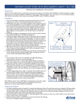
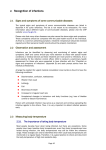
user manual FOR
long term care
and low beds
www.drivemedical.com
inspection maintenance plan
PACKAGING/HANDLING INSPECTION
INSPECTION OF ALL COMPONENTS
1.
Inspect – Receipt of shipment
Check bed components for obvious damage.
2. Inspect power supply cord for cuts and/or damage.
3. Check that the actuator cords are connected properly into the control box.
ASSEMBLY INSPECTION-MECHANICAL
SLEEPING SURFACE, FRAME AND BASE ASSEMBLIES Inspect – 1 Year
1.
Inspect welds on the sleeping surface, frame and base assemblies for
stress fractures.
2. Inspect all fasteners for wear and looseness.
HEAD/FOOT AND HI/LO ACTUATOR/PULL TUBES
Inspect – 1 Year
1.
Inspect head, foot and hi/lo torque tube components for excessive wear.
2.
Inspect head, foot and hi/lo torque tubes for bends, wear or stress damage.
Clevis pins on head, hi/lo pull tubes should not be bent.
2. Tighten all actuator mounting hardware.
CASTERS
1.
Inspect – 1 Year
Check locks on both locking casters to ensure they are operational.
2. Check casters to ensure they roll properly.
1
assembly inspection
ELECTRICAL
CONTROL BOX
1.
Inspect – 6 months
Check power cord for chafing cuts or wear.
2.Make sure all attaching hardware is securely tightened.
3. Check electrical connections for wear or fractures.
PENDANT
1.
Check pendant cord for chafing cuts or wear.
2.
Check all pendant functions:
• Head raises and lowers properly.
• Foot raises and lowers properly.
• Bed raises and lowers properly (full electric only).
Inspect – 6 months
Note: Follow electrical troubleshooting guide if failures are experienced.
2. Check to make sure each button and associated function correspond
ACTUATORS
1.
Inspect – 6 months
Check actuator cords for chafing cuts or wear.
2. Check range of movement on all motors to ensure they do not bind in the FULL
UP or FULL DOWN position.
Note: Should binding occur, adjust the pull tube of the actuator by turning it
clockwise or counter clockwise (in or out) just enough to allow the motor to shut
off automatically. Failure to do so will damage the head, foot, hi/lo function, and
the internal gears of the actuator.
3.Lubricate acme screws as needed with petroleum jelly.
2
safety summary
WARNING/ CAUTION
Labels applied to the bed apply to hazards or unsafe
practices that could result in personal injury and/or
property damage.
NOTICE:
The information contained in this document is subject to change without notice.
Check all parts for shipping damage and test before using. In case of damage,
do NOT use.
WARNING – OPERATING INFORMATION:
When using nasal or masked type administering equipment, oxygen or air tubing
MUST be routed and secured properly to ensure that tubing does NOT become
entangled and eventually severed during normal operation of Manual/Electric bed.
Keep all moving parts free of obstructions (i.e. blankets/sheets, heating blankets/
pads, tubing, wiring, etc. and other types of products).
DO NOT use the side rails as push handles for moving the bed.
Trapeze units must be used ONLY in ASSISTING the patient in repositioning or
transferring in or out of bed. NEVER allow patients to use a trapeze unit as a total
individual weight support.
NEVER permit more than one (1) person on/in the bed at any time.
Body weight should be evenly distributed over the sleeping surface of the bed.
DO NOT lay, sit or lean in such a way that your entire body weight is placed only on
RAISED head or foot sections of the bed. This includes when assisting in
repositioning or transferring in or out of bed.
3
safety summary
continued
ELECTRICAL
The bed is equipped with a three-pong (grounding) plug for protection against
possible shock hazard. DO NOT, under any circumstances, cut or remove the round
grounding prong from any plug used on the bed.
DO NOT remove caution/warning labels applied to bed.
NEVER operate the bed if a cord or plug is damaged, or if it is not working properly;
contact Qualified Service Personnel for examination and repair.
REPAIR OR SERVICE INFORMATION
Do NOT open assemblies such as the actuators, hand control, and control box. If
uncertified individuals perform work on these products, the warranty is voided.
DO NOT use unauthorized parts, accessories, or adapters.
Unplug the power cord when performing and maintenance on the bed.
RADIO FREQUENCY INTERFERENCE
Most electronic equipment is influenced by Radio Frequency Interference (RFI).
Caution should be exercised with regard to the use of portable communications
equipment in the area around such equipment. If FFI causes erratic behavior, shut
the bed OFF immediately. Leave OFF while transmission is in progress.
WEIGHT LIMITATION
The weight limitation for Manual/Electric bed; taking into consideration patient size,
proper positioning, realignment, transfer and overall care; is 450 pounds.
4
PACKAGING/HANDLING INSPECTION
INSPECTION OF ALL COMPONENTS
1.
Inspect – Receipt of shipment
Check side rail components for obvious damage.
2. Check hardware package assuring all hardware is available for proper assembly.
ASSEMBLY INSPECTION-MECHANICAL
SIDE RAIL ASSEMBLY
1.
Inspect – 3 months
Inspect side rails welds for stress fractures.
2. Inspect all fasteners for wear and looseness, replace and tighten as needed.
3. Bent side rails should be replaced immediately.
4.Lubricate all pivot points as needed.
SAFETY SUMMARY
Side rails when used with a Manual/Electric bed DO NOT fall within any weight
limitations. Side rails can be deformed or broken if excessive side pressure is
exerted on the side rails. These side rails are for the purpose of preventing an
individual form inadvertently rolling/climbing out of a bed. If an individual is
capable of injuring himself/herself, an alternative means of preventing the
patient from rolling/climbing out of a bed should be initiated.
Additional safety measures should be considered for patients identified as high
risk for entrapment. Such patients include those with pre-existing conditions
such as confusion, restlessness, lack of muscle control, altered mental status
(organic or medication related), or a combination of these factors. Increased
risk also occurs when the patient’s size and/or weight are inappropriate for the
bed’s dimensions.
DO NOT use the side rails as push handles for moving the bed.
5
long term care bed
SPECIFICATIONS
DIMENSIONS
80” LTC
MANUAL
80” LTC
ELECTRIC
80”
LOW BED
Overall Length (Includes 1/2” rubber bumper)
85.75”
85.75”
85.5”
Overall Width (With rails)
40”
40”
40”
Overall Width (With boards)
36.5”
36.5”
35”
Overall Width (Without boards)
34.5”
34.5”
34.5”
Length of Mattress Surface
79.5”
79.5”
79.5”
Mattress Platform Height (Low Position)
15”
15”
8”
Mattress Platform Height (High Position)
26”
26”
17.5”
Maximum Knee Elevation
45°
45°
45°
Maximum Head Elevation
80°
80°
80°
6
patient controls
Full electric beds are equipped with a pendant type hand control as standard
equipment. Each control function (head, knee, and bed) has two clearly identifiable
switches for up and down travel. The controls are designed to prevent damage to the
motor in the event that both the up and down functions are activated simultaneously.
HEAD UP
HEAD DOWN
BED UP
BED DOWN
FOOT UP
FOOT DOWN
7
electrical specifications
115 VOLT HIGH/LOW MOTOR:
115 VOLT HEAD/FOOT MOTOR:
•
•
•
•
•
•
•
•
•
•
•
•
•
•
4.0 Amps maximum
115 Volts AC, 60 cycles
Automatic thermal protection
1/10 H.P.
Gear Ratio 19:1
Permanently lubricated internally
Instant reversing
4.0 Amps maximum
115 Volts AC, 60 cycles
Automatic thermal protection
1/10 H.P.
Gear Ratio 19:1
Permanently lubricated internally
Instant reversing
PRINTED CIRCUIT BOARDS
All circuit boards are tested by the board manufacturer, and by B.A.M.P. assembly
department prior to shipping.
ELECTRICAL CORD AND PLUG
Hospital grade, U.L./C.S.A. listed. The cord extends 92” from the end of the bed.
8
assembly instructions for long term care beds
MANUAL & ELECTRIC LTC BEDS
1.
Open carton and check to make sure all parts are there and not damaged.
2.Lay bed spring (A) on one of its sides.
3.
Place casters (B) in all four legs. Tilt frame slightly to put the casters on when working on
the floor side.
4.Lay bed down on all four casters
5.
Place the long mounting bracket (C) on the head board (D) (the larger of the two wood
panels).
6.
Place head board (D) into the slots on the head section of the bed spring.
Place long bolts and tighten to secure.
7.Assemble the foot board by attaching the two angled mounting brackets (E) to the foot
board (F) (the smaller of the two wood panels)
8.Rest footboard on foot section of bed
9.Align the holes in the mounting bracket with the holes in the foot spring section and
attach using four bolts.
10. If manual bed crank bed up several inches. If electric use Hilo button to raise bed
several inches.
11.Attach the four resting legs (G) on the four plates on both sides of bed.
12. If side rails are present mount the cross bar in the desired position using the holes on the
bed spring frame (make sure you have proper clearance from side to side as rails moves
in a side ways motion.)
D
13.Slide side rail over the cross bar and tighten nut.
C
F
B
A
E
G
9
assembly instructions for low bed
1.Lay bed down on all four casters
2. Place the long mounting bracket (C) on the head board (D) (the larger of the
two wood panels).
3. Place head board (D) into the slots on the head section of the bed spring.
Place long bolts and tighten to secure.
4.Assemble the foot board by attaching the two angled mounting brackets (E) to
the foot board (F) (the smaller of the two wood panels)
5.Rest footboard on foot section of bed
6.Align the holes in the mounting bracket with the holes in the foot spring section
and attach using four bolts.
7. If manual bed crank bed up several inches. If electric use Hilo button to raise bed
several inches.
D
C
F
B
A
E
10