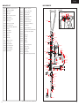
1
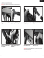
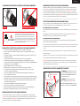
USER MANUAL
English
Français
English
.68 Caliber Semi Automatic Paintball Marker
TABLE OF CONTENTS
IMPORTANT SAFETY GUIDELINES
1
OPERATION GUIDE / START UP
2
8 STEPS TO START AND PLAY
3-4
CRITICAL SAFETY INFORMATION
5
RECOMMENDED PAINTBALL SAFETY GEAR
6
CO2 / COMPRESSED AIR TANK WARNINGS
7
INSTALLING / REMOVING / CO2 / COMPRESSED AIR TANK
7-8
PROPER USE OF BARREL BLOCKING DEVICE
8
VELOCITY ADJUSTMENT INCREASE / DECREASE
8-9
A JAMMED PAINTBALL
9
QUICK CLEAN / DISASSEMBLE / REASSEMBLE REAR INTERNALS
9-10
CUP SEAL REMOVAL GUIDE
11
TROUBLESHOOTING
12
AIR LEAKS
12
MR1 PARTS LIST
13
MR1 SCHEMATIC
14
WARRANTY STATEMENT
15
English
IMPORTANT SAFETY GUIDELINES
WARNING
•
•
•
•
•
•
•
•
•
•
•
•
•
•
•
•
•
•
•
•
•
•
•
1
This paintball marker is NOT a toy. Misuse can cause serious injury or death.
Kingman recommends that the customer be at least 18 years of age to purchase this product.
Person under 18 years of age must have adult supervision when using this product.
Read this User manual before using this product.
Any modifications or tampering of original factory parts or use non authorized aftermarket
accessories will void all warranties and liabilities from Kingman.
Keep the barrel blocking device on marker when not shooting/playing.
To ensure proper adjustment of velocity Feet per Second (fps), Kingman strongly recommends
using a chronograph for paintball use located or purchased at most paintball stores and paintball
fields. The discharges of paintballs are high velocity and high impact that can cause serious
injuries or death if misused.
Before / after use of the marker, check and make sure all screws are securely tightened. Loose
screws may prevent the marker from functioning properly. A paintball marker NOT properly
maintained can be dangerous and can cause serious injury or death.
Any person using this product or within range of this product while it is in use MUST wear
EYES/FACE, EARS PROTECTION designed specifically for the sport of paintball. This includes,
but is not limited to, performing a maintenance, velocity check and target practice.
Kingman reminds the user that SAFETY IS YOUR RESPONSIBILITY. Protect your eyes/face
and ears at all times, and will not be held liable for injuries or death sustained when failing to
follow the safety guidelines.
Never shoot or point your marker at a person that is not in a designated paintball facility and
without proper paintball EYES/FACE/EARS PROTECTION. The protection includes and not
limited to the protection of eyes, face, ears, neck and head. Avoid shooting underneath the
paintball goggles.
DO NOT point or shoot at any Law Enforcement Officer.
Treat every paintball marker as if it were loaded.
Never look down the barrel of a loaded or unloaded marker.
Always keep the paintball marker in SAFE mode until ready to operate.
Always remove the air source and all paintballs from the marker, includes paintballs inside the
breach of the marker, before disassembly.
Fire only 0.68 caliber paintballs with this product.
Always make certain the bolt of the marker is in the un-cocked position when not shooting/playing.
Using a paintball marker outside of a non designated paintball field can be illegal, and is subject
to law enforcement penalties if property damage is caused by the user.
Never point or shoot your marker at an animal.
Never point the barrel toward yourself while playing, running or stumbling to avoid shooting
underneath your paintball goggles.
Wear appropriate dress to avoid any exposure of skin to protect you when playing paintball games.
Transfer this User manual upon change of marker ownership.
Please visit www.spyder.tv for the latest User Manual updates..
OPERATION GUIDE / START UP
1.
2.
Always attach a barrel blocking device over the tip of the barrel for safety precautions when not shooting/playing.
Have the marker in the “SAFE” position before use. To operate, push the safety button from the “PUSH SAFE”
side of the trigger frame. This will position the marker in a lock safe mode. To disengage the safety button in a safely
manner, point the marker in a safe direction, and push the safety button towards the opposite side of the trigger
frame. Do not disengage safety button until step 6.
3. Attach a CO2 / Compressed Air Tank to the C/A Adapter. HELPFUL TIP: Make sure to have the CO2 / Compressed
Air Tank filled before attaching to the marker. Hand tightens the tank clockwise in the markers C/A adapter until it is
snug. If an air leak occurs between the tank and the C/A adapter, replace the urethane O-ring. NOTE: O-rings in the
markers parts kit are not supplied to attach with a CO2 / Compressed Air Tank. IMPORTANT: You should never need
to use any hand tool to attach a CO2 / Compressed Air Tank to the C/A adapter. (See CO2/Compressed Air Tank
Warning)
4. Attach an elbow and paintball loader to the markers feed neck. NOTE: Small hole on the elbow must fasten to the
markers feed neck and larger hole to the loader. Elbows with adjusting screws must tighten accordingly. NOTE: Fill
your paintball loader with only .68 caliber paintballs.
5. Cocking the marker. Pull the Top Cocking Knob rearward until the Delrin Bolt latches. CAUTION: Should you let go of
the Top Cocking Knob before it latches, your marker may fire.
6. Remove the barrel blocking device over the barrel. Now you can release the safety button. CAUTION: With the
safety button released in the FIRE position the marker is ready to shoot/play. By pulling the trigger will fire a
paintball. IMPORTANT: Only test your marker in a safe direction or in a designated playing field.
7. Performing a velocity (fps) check. Turning the velocity adjuster & spring guide clockwise will increase the velocity
(fps) while turning counter-clockwise will decrease the velocity (fps). NOTE: Your marker is intended to be used in
a paintball facility with the proper paintball protection. IMPORTANT: Kingman recommends using a chronograph to
ensure that the marker’s velocity is under 300 (fps).
8. When finished playing, remove all paintballs from the paintball loader before detaching from the markers feed neck
by loosening the screws on the elbow. CAUTION: There may be paintballs in the marker’s breach; take a couple of
shots in a safe direction to make sure the barrel and receiver are empty.
9. Place the barrel blocking device over the barrel tip. This will help avoid any accidental discharge.
10. The marker must be in the “SAFE” and un-cocked position after use.
11. Unscrew the CO2 / Compressed Air Tank from the marker’s C/A adapter. Firmly hand loosens the tank counterclockwise to detach it from the marker’s C/A adapter. CAUTION: Never expose any skin underneath the C/A
adapters bleed hole when removing the tank. This can run the risk of getting skin burn from the releasing of the GAS.
IMPORTANT: You should never need to use any hand tool to detach a CO2 / Compressed Air Tank. (See CO2/
Compressed Air Tank Warning)
12. Store the marker in a paintball bag or in a safe place. WARNING: Before / after use of the marker, make sure to
fasten all screws. Loose screws may prevent the marker from functioning properly. HELPFUL TIP: It’s a good
practice to lubricate your marker before and after each use, especially when storing the marker for an extended
period of time. Add a few drops of paintball gun oil on the Striker O-ring (see Disassemble / Reassemble). Before
storing the marker, make sure the marker is in the safe mode, un-cocked position without air source attached, any
paintball inside the marker has been removed and with barrel blocking device on.
IMPORTANT
•
Firing velocity may vary according to altitude and climate conditions.
•
It may be dangerous approximately within 300 feet (100 meter) of shooting range.
•
Before using your marker in play, you must always first perform a “SAFE VELOCITY TEST”. This can only be
accomplished by using a testing device called a “Velocity Chronograph“ and can be performed at a paintball dealership
or local playing field. NOTE: This product is intended to be used at a velocity no greater than 300 feet per second
(fps). Paintball markers are not intended to shoot within 30 feet.
•
This paintball marker may have excess gas after the removal of the CO2 / Compressed Air Tank. Please remove all
paintballs and discharge the remaining gas safely.
•
Never store a CO2 / Compressed Air Tank attached on the marker.
2
English
8 STEPS TO START AND PLAY
IMPORTANT: Please read the Safety and Operation Guidelines before you start the 8 quick steps to Start and Play.
1.
Make sure the safety is ON
3.
Install a CO2/Compressed air tank
2.
Insert the barrel blocking device
4.
Install a paintball loader and add
paintballs in the loader
5.
Put on your paintball goggles and
cock back the marker
7.
Unlock the safety
6.
Remove the barrel blocking device
8.
Ready to play fire
IMPORTANT: Make sure the Marker is in the SAFE MODE and the barrel blocking device is on the Marker’s barrel
after PLAY.
* The model shown is for picture only. It may not represent the model you have.
3
4
RECOMMENDED PAINTBALL SAFETY GEAR
Cap or Hood
NEVER look down the barrel with
or without your paintball goggles
ON.
Paintball Goggles
NEVER look down the barrel of a
loaded or unloaded marker.
Neck Protector
Paintball Jersey
w/ Body Armor
under
WARNING: UNSAFE
NEVER shoot or point your
marker at a person that is not
in a designated paintball facility
and without proper EYES/FACE/
EARS protection designed
specifically for the sport of
paintball.
Protective
Gloves
WARNING: UNSAFE
Padded Pants
Before / after use of the paintball
marker, check and make sure all
screws are securely tightened.
Loose screws may prevent the
paintball marker from functioning
properly.
NOTE: Some screws may not be
highlighted in diagram.
5
IMPORTANT: Please read the Owner’s Manual before you play.
* The model shown is for picture only. It may not represent the model you have.
Athletic Shoes
Wear appropriate dress attire to avoid any exposed skin when playing paintball. We
recommend purchasing a Paintball Goggles, Neck Protector, Paintball Jersey or Long
Sleeve shirt, Body Armor, Protective Gloves, Athletic Shoes and Padded Pants.
6
English
CO2 / COMPRESSED AIR TANK WARNINGS
REMOVING A CO2 / COMPRESSED AIR TANK
Firmly unscrew the CO2 / Compressed Air Tank by turning the tank counter-clockwise until it comes out of the C/A
Adapter. HELPFUL TIP: After firing the marker, you should ALWAYS remove the CO2 / Compressed Air Tank before
storing. When the tank is being removed, excess air will release from the C/A Adapter. CAUTION: Never expose any
skin to the C/A Adapters bleed hole when removing the tank. This is to avoid the risk of getting skin burn from the
escaping GAS.
IMPORTANT: You should never need to use any hand tool to detach a CO2 / Compressed Air Tank from the C/A
Adapter. If you cannot remove a tank by hand please see a certified airsmith for assistance.
PROPER USE OF YOUR BARREL BLOCKING DEVICE
WARNING:UNSAFE
SAFE
DANG E R
The CO2 or Compressed Air Tank can fly off with enough force to cause serious
injury or death if the Valve unscrews from the cylinder head. LOOK at the Valve
when removing the cylinder from the marker. Be sure that the valve is turning
with the cylinder rather than remaining stationary with the marker. STOP if the
Valve starts to unscrew from the cylinder. If in doubt, screw the cylinder back
onto the marker and contact a trained person for repair.
CO2 / COMPRESSED AIR TANK WARNINGS
•
•
•
•
•
•
•
•
•
•
•
•
•
•
•
All valves must only be installed or removed by a qualified airsmith.
See CO2 / Compressed Air tank labels for retest dates. Cylinder tanks must be retested
periodically.
Improper use, filling, storage or disposal of all air cylinders may result in death, personal injury
and/or property damage.
Always keep cylinders out of reach from children or any inexperienced person(s).
Only properly trained personnel in accordance with CGA Pamphlets P.1 and G-6.3 must fill all air
cylinders. Pamphlets are available from the Compressed Gas Association or www.CGANET.com.
Never alter the cylinder in any way.
DO NOT expose pressurized cylinders to temperatures in excess of 130˚F (54˚C).
Cylinders heated to an excess of 250˚F (121˚C) must be condemned or requalified in accordance
with test defined in CFR-49.
The valve should NEVER be detached from the canister. Please seek immediate assistance from a
trained airsmith should this occur.
Any tank packed with the product is intended for paintball use only.
Confirm that there is an attached urethane O-ring on the CO2 / Compressed Air tank valve before
attaching the tank to the marker. The tank will leak air as soon as it is secured to the marker, if the
O-ring is missing from the valve.
A urethane O-ring is highly recommended before attaching any air supply to the marker.
NEVER over pressurize a CO2 / Compressed Air cylinder.
Avoid any direct skin exposure to the escaping gas, when installing or removing any air supply.
Never expose cylinders to corrosive materials or clean with any caustic cleaners.
INSTALLING A CO2 / COMPRESSED AIR TANK
Firmly screw the CO2 / Compressed Air Tank clockwise into the markers C/A Adapter. HELPFUL TIP: Before installing
a CO2 / Compressed Air Tank, make sure that the tank is full and that it has a urethane bottle on the top of the valve to
prevent air leaks.
A Barrel Blocking Device or “BBD” is an essential part of your paintball safety equipment. The Barrel Blocking Device
is designed to stop a paintball from exiting a paintball marker accidentally. Improper use of the Barrel Blocking Device
will render this device useless.
BARREL SOCK/BAG TYPE DEVICE
Place the bag/sock part of the Barrel Blocking Device over the end of your barrel and wrap the elastic cord around the
back end of your marker.
Adjust the length of the elastic cord to make sure your Barrel Blocking Device fits securely over your markers barrel.
NOTE: If the elastic cord is too long you can tie a couple of knots around the cord to shorten its length.
BARREL PLUG TYPE DEVICE
Insert the barrel plug securely into the end of your markers barrel before proceeding to load paintballs and screwing in
your tank to your marker.
The barrel plug should fit firmly into the barrel with a significant amount of resistance. NOTE: The barrel plug should
not be easy to remove and always inspect the O-rings to make sure they are not worn or cut.
IMPORTANT: Remove the Barrel Blocking Device only when you are getting ready to begin play or have been
instructed to do so by a field safety official.
Always keep your Barrel Blocking Device on your marker after you have finished playing. Keep it in place
even after you have emptied all paintballs and removed your air tank from your paintball marker.
WARNING: Inspect your Barrel Block Device regularly for wear and any tear if it is worn, replace it immediately.
Always have your Barrel Blocking Device in place on your markers barrel to insure safety and prevent accidents that
may cause permanent injury or even death.
VELOCITY ADJUSTMENT INCREASE / DECREASE
Decrease Velocity
To INCREASE your velocity FPS (Feet Per Second)
using the Allen wrench turn the Velocity Adjuster / Spring
Guide clockwise.
To DECREASE your velocity FPS (Feet Per Second)
using the Allen wrench turn the Velocity Adjuster / Spring
Guidev counter-clockwise.
Increase Velocity
STP011
VTA008
IMPORTANT: You should never need to use any hand tool to attach a CO2 / Compressed Air Tank to the C/A Adapter.
7
8
English
VELOCITY ADJUSTMENT INCREASE / DECREASE CONT.
Quick Clean Disassemble
WARNING
Lift upward on the Top Cocking knob. This will allow the Venturi Bolt sliding from the rear of the Receiver.
HELPFUL TIP: With the Venturi Bolt removed out of the Receiver, this allows easy access to clean with a squeegee.
NOTE: Make sure the hole on the Striker Bolt is facing upright when looking thru the Receiver. This will allow the
Top Cocking Knob to correctly fasten with the Striker Bolt. HELPFUL TIP: Please note how the parts are removed
for easy reassembly
•
The recommended Velocity speed should be no greater then 300 fps. Not doing so can cause serious injury if
the Velocity is dangerously high.
•
Paintball markers are not intended to shoot any person less then 25 feet.
•
Never point a loaded marker at any person who is not wearing the proper face protection.
•
Never at any point should you look down the barrel, whether the marker is loaded or not.
Disassemble Rear Internals
•
Using a paintball marker outside a non designated paintball field can be illegal, and is subject to law
enforcement penalties if property damage is caused by the user.
STEP 1 Lift upward on the Top Cocking knob. This will allow the Venturi Bolt slide out from the rear of the Receiver.
A JAMMED PAINTBALL
In the event of a paintball break and the Bolt jams, follow these steps to help un-jam the marker. The markers
breach is located where the barrel starts to thread in the Receiver and underneath the markers feed neck. Before
attempting to un-jam the Bolt you should always have your Paintball Goggles on. Make sure the marker is in
the SAFE / OFF position before attempting to un-jam the Bolt. Remove the CO2 / Compressed Air Tank before
attempting to un-jam the marker. Remove all paintballs and the loader from the feed neck. Have the barrel removed
from the Receiver to allow the paintball(s) to exit. With enough force tension on the Top Cocking Knob, pull back
to release the Bolt from the jammed position. Another method is to use a “Straight Shot Squeegee” or the end of a
wood dowel rod; push against the face of the Bolt with enough force to release the jammed Bolt. Always clean the
paint from the breach and barrel to enhance the performance of your marker.
IMPORTANT: Never look down the barrel of the marker when loaded or unloaded. Remove the attached CO2 /
Compressed Air Tank before attempting to un-jam the Bolt.
STEP 2 Remove the Quick Disconnect Pin. This will allow the Striker Plug and the markers internals to side from
the rear of the Receiver. NOTE: Remove the Quick Disconnect Pin when the markers in the de-cocked position. This
way, the tension of the Striker Spring does not allow the markers internals to spring out. HELPFUL TIP: Placing
your finger behind the Striker Plug before removing the Quick Disconnect Pin will prevent the markers internals to
spring out.
STEP 3 Remove items in order: Striker Plug w / Velocity Adjuster, Striker Spring and Striker Buffer.
STEP 4 Slide the Striker Bolt out of the rear of the Receiver. HELPFUL TIP: When the internals are removed it
would be wise to clean any dirt or paint from the inside of the Receiver with a squeegee. Wipe clean the Venturi Bolt
with a rag or paper towel. Apply some paintball gun on the Striker O-ring periodically.
Reassemble Rear Internals
NOTE: Never use a metal rod or screwdriver as a tool to push on the Bolt, anything metal will scratch and damage
the inside of the marker.
STEP 1 Reinsert the Striker Bolt thru the rear of the Receiver with the o-ring facing towards the front of the
marker. NOTE: Apply thumb pressure behind the Striker Bolt and at the same time pull on the Trigger. Repeat this
process until the Bolt is fully inserted. NOTE: The hole on the Striker Bolt should be facing upright when looking thru
the Receiver. This will allow the Top Cocking Knob to correctly fasten with the Striker Bolt.
QUICK CLEAN & DISASSEMBLE / REASSEMBLE REAR INTERNALS
STEP 2 Insert the Striker Buffer flush with the Receiver and place the Striker Spring thru the Striker Buffer.
STEP 3 Place the Striker Plug w / Velocity Adjuster & Spring Guide to the rear of the Receiver.
STK003
VTB006
STP011
STF001
REC003
REC011
STB002
SPR004
VTA008
9
STEP 5 Insert the Venturi Bolt thru the rear of the Receiver with the Top Cocking Knob. Press downward on the
Top Cocking Knob to gain entry with the Striker Bolt. NOTE: If the Striker Bolt hole is not aligned upright, the Top
Cocking Knob will not fasten correctly with the Striker Bolt. HELPFUL TIP: Use a small tool devise to align the hole
upright should the Striker Bolt turn when positioned back in the Receiver. IMPORTANT: The Quick Disconnect Pin
must be properly placed thru the Receiver. The ball bearing on the pin must be visible thru the opposite end of the
Receiver.
To assure marker is assembled properly, follow the schematic drawing or position parts in order during disassembly.
Parts assembled backwards or improper parts installed will / can cause the marker to malfunction.
WARNING
Never attempt to remove the markers internals while the CO2 / Compressed Air Tank is attached. Make sure to
remove all paintballs and loader before disassembling the marker.
RPN009
Part Names and Numbers describe in this section:
Top Cocking Knob (#STK003)
Venturi Bolt (#VBT006)
Striker Bolt (#STB002)
Quick Disconnect Pin (#RPN009)
Receiver (#REC003/REC011)
STEP 4 Insert the Quick Disconnect Pin thru the Receiver to hold the Striker Plug in place.
Striker Spring (#SPR004)
Striker Buffer (#STF001)
Striker Plug (#STP011)
Velocity Adjuster (#VTA008)
10
English
CUP SEAL REMOVAL
TROUBLESHOOTING
One ore more of the following may cause recocking related issues:
REC003
REC011
•
Need lubrication on the following O-ring (#ORG001) (See Disassemble / Reassemble).
•
The pressure in the tank is too low and possibly needs to be refilled.
•
Striker O-ring (#ORG001) is damaged or missing. Replace with a new Kingman approved Striker O-ring.
NOTE: The Striker O-ring cannot be substituted with a black or urethane bottle o-ring.
•
Dirt or broken paint shell fragments in the Receiver can cause the marker to have recocking issues. Using a
squeegee thru the upper portion of the Receiver will remove most of the dirt or broken shell fragments. Should
this issue continue please (See Disassemble / Reassemble) to remove the markers internals for complete
cleaning
•
Using low quality paintballs can cause the marker to experience recocking issues cause of the shape of the
paintballs.
ITP012
LPC011
ITP013
ITP011
SPR007
ORG002
HELPFUL TIP: Paintballs have a shelf life and can become too fragile for use. Paintballs can take a different shape
in time so would be wise to size the paintball with your barrel.
SCR016
AIR LEAK
IMPORTANT: Always remove the air tank before any disassembling of the marker.
Part Names and Numbers describe in this section:
Vertical Screw (#SCR016)
Valve Pin (#ITP013)
Cup Seal Guide (#ITP011)
Cup Seal (#ITP012)
O-ring #15 80D (#ORG002)
Valve Spring (#SPR007)
Reservoir Plug (#LPC011)
Receiver (#REC003/REC011)
CUP SEAL REMOVAL
The following steps will provide easy access to the Cup Seal. The sign of a worn out Cup Seal is the presence of
CO2 / Compressed Air leaking down the barrel.
STEP 1 Loosen the M5 x 12 Screw that holds the Reservoir Plug in front of the Foregrip.
STEP 2 Slide the Reservoir Plug out of the Receiver.
STEP 3 Once the Reservoir Plug has been removed the Valve Spring, Valve Pin, Cup Seal Guide and Cup Seal will
be attached.
STEP 4 Detach the Valve Spring from the Reservoir Plug, and then unscrew the Cup Seal from the Valve Pin.
Replace the Cup Seal with a new one supplied in the Spare Parts Kit.
•
Air leaking from the Vertical Adapter means the O-ring (s) (#ORG002) will need to be oiled or replaced.
•
Air leaking down the barrel is usually caused by a worn or damaged Cup Seal (#ITP012). (SEE CUP SEAL
REMOVAL) should the Cup Seal need to be replaced?
•
Never remove or tamper with the Valve Body (#ITP018) unless specifically repairs are needed.
•
A nick or scratch on the lip of the Valve Body can cause an internal air leak. (SEE CUP SEAL REMOVAL)
should the Valve Body need to be replaced?
•
Air leaking thru the Receiver and out of the Trigger Frame would indicate the Valve Body O-ring (s)
(#ORG002) will need to be replaced.
•
Air leaking thru the opposite end of the hose fittings please check the following. The Female end of the
Hose must have a plastic washer (#HSF004) installed inside the hose collar and be tightened properly. The
Male end of the Hose must have a hose o-ring (#ORG004) at the end of the male side of the hose at all
times.
IMPORTANT: The hose line supplied has a Metric Female and Metric Male ends. This will not install into American
(NPT) threaded fittings. If installed incorrectly it’s possible to damage the entire attachment fittings and hose line.
To assure marker is assembled properly, follow the schematic drawing or position parts in order during disassembly.
Parts assembled backwards or improper parts installed will / can cause the marker to malfunction.
STEP 5 Detach the Valve Spring from the Vertical Adapter, and then unscrew the Cup Seal from the Valve Pin.
Replace the Cup Seal with a new one supplied in the Spare Parts Kit.
Once these steps have been completed, replace the damaged Cup Seal and reassembly all parts back in the Receiver.
HELPFUL TIP: Please note how the parts are removed for easy reassembly.
CAUTION: Use the proper Allen wrenches to fasten all screws and never apply more force than necessary.
IMPORTANT: Always remove the Air Tank before any disassembly of your marker. Do not remove the Valve Body unless
specific Valve Body repairs are needed. Do not remove the Valve Body with a screwdriver as it will damage the Valve Body
Lip and cause air leaks. NOTE: The Valve Body Screw screw must be removed prior to taking out the Valve Body.
11
12
English
MR1 PARTS LIST
ASA011
BAR001
BAR011
BLS003
DRF011
FND011
FRG002
FRG011
GRP003
HSE005
HSE006
HSF001
HSF004
ITP011
ITP012
ITP013
ITP018
LPC011
ORG001
ORG002
ORG003
ORG004
ORG008
* PAK002
MR1/MR2 Dovetail Bottom-Line ASA
Spyder Barrel Plug/BBD
MR1 12’ Barrel
Ball Stopper
MR1 2” Dovetail Drop Forward
MR1 Feed Neck
MR1 Shoulder Stock
MR1 Foregrip
Rubber Grip Cover (black)
Disconnect Hose 7.75”
Male to Male Adapter (MET x MET)
Air Filter
Plastic Washer
Cup Seal Guide
Cup Seal
Valve Pin
Valve Body
MR1 Reservoir Plug
Striker O-Ring
O-Ring #015 80D
Barrel O-Ring (black)
#011 O-ring (black)
#010 O-ring (black)
Spare Parts Kit
MR1 SCHEMATICS
REC003
REC011
RPN004
RPN005
RPN006
RPN007
RPN009
SAB002
SCR002
SCR007
SCR010
SCR016
SCR020
SER002
SPR004
SPR007
SPR008
STB002
STF001
STK003
STP011
TRF004
TRS003
VBT006
VTA008
MR1 Receiver (OD green)
MR1 Receiver (matte black)
Trigger Roll Pin (large)
Sear Roll Pin (med)
Secondary Roll Pin (small)
Valve Body Roll Pin
MR1 Quick Disconnect Pin
Safety Button Set (med)
M4 x 8 Grip Screw w/Washer (A)
Valve Body Screw
Drop Forward Lock Screw
TRIGGER
RPN005 SER002
SAB002
RPN006
RPN004
FRG002
SPR008
SPR011
M5 x 12 Trigger Frame Screw w/Star Washer (ASH)
Foregrip Fixing Screws w/washers
Sear
Striker Spring
Valve Spring
Sear Spring
Striker Bolt
Striker Buffer
MR1 Pull Pin Cocking Knob
MR1 Striker Plug
Metal Trigger Frame
Double Trigger
MR1 Venturi Bolt
Velocity Adjuster & Spring Guide (matte black)
STP011
ORG002
VBT002
VBT004
VBT003
STF001
ORG008
VTA008
SCR002
STK003
SPR004
GRP003
VBT006
STB002
DRF011
SCR016
ORG001
SCR016
RPN009
SCR016
ORG004
TRS004
HSE006
REC003
REC011
SCR002
RPN007
TRS003
HSF004
ORG019
SCR010
SCR016
HSF001
HSE005
SCR002
FND011
BLS003
ORG003
ITP018
SCR020
HSE007 FRG011
ORG004
ORG002
SCR007
ORG002
ITP013
ITP012
ITP011
SPR007
ORG002
BAR001
SCR016
LPC011
BAR011
13
* Item Not Pictured (+) Cross-head Screw (A) Allen-head Screw
14
WARRANTY STATEMENT
Kingman warrants the original retail purchaser that this product is free from defects in material and
workmanship under normal use and service for a period of (1) year from the original date of purchase.
Any Electronic Components in an Electronic Spyder marker are warranted for (6) months from the
original date of purchase. Kingman agrees to repair or replace (at its discretion) any product within (a
reasonable period of time). This warranty does not cover o-rings, cup seals, 9.6v rechargeable battery,
charger, scratches, nicks, normal wear and tear of parts, any modifications, normal fading of anodizing
and damage caused by dropping or hitting of products. This warranty shall not apply if it is shown by
a Kingman Technician that the consumer caused the defect or malfunction because of misuse. This
warranty only covers original factory parts. Any modifications or tampering of original factory parts
will VOID warranty and liabilities from Kingman. Any damage caused by water will not be covered
under warranty. Warranty repair can only be conducted by Kingman technician or Kingman authorized
technician. For warranty to be effective, consumer must return the enclosed warranty registration
card filled out, along with a copy of the purchase receipt, within (15) days of the original purchase
date. This warranty is not transferable. Paintball markers are non-refundable. This warranty will not
cover pick up, shipping, delivery, and/or house calls. If product needs repair, consumer will package
it carefully and send together with your name, address, phone number and a brief description of the
malfunction to:
KINGMAN GROUP
Attn: Tech Department
14010 Live Oak Avenue
Baldwin Park, CA 91706 U.S.A.
www.kingman.com
» Warranty Registration is also available at www.spyder.tv
FOR TECHINICAL SUPPORT
Our Technical Support Department is open Monday through Friday, from 8am to 5pm (PST), and can be
reached at (626) 430-2300.
www.spyder.tv
15
12
Français
Marqueur De Paintball Semi Automatique De Calibre .68
TABLE DES MATIERES
15
13
IMPORTANTES CONSIGNES DE SECURITE
19
MISE EN ROUTE
20
8 ETAPES POUR COMMENCER A JOUER
21-22
INFORMATIONS IMPORTANTES DE SECURITE
23
EQUIPEMENT DE SECURITE RECOMMANDE POUR LE PAINTBALL
24
CONSIGNE DE SECURITE SUR LA BOUTEILLE DE CO2/AIR COMPRIME
25
MONTER ET DEMONTER LA BOUTEILLE DE CO2 / AIR COMPRIME
25-26
UTILISATION APPROPRIEE DU BOUCHON DE CANON 26
REGLAGE DE LA VELOCITE
26-27
BILLE COINCEE DANS LA DESCENTE DE BILLE
27
DEMONTAGE/NETTOYAGE/ REMONTAGE DES PIECES INTERNES
27-28
GUIDE DE DEMONTAGE DU CUP SEAL
29
GUIDE DE PANNES
30
FUITE D’AIR
30
LISTE DES PIECES DU SPYDER MR1 31
SCHÈMAS DU SPYDER MR1 32
POLICE DE GARANTIE
33
18
Français
IMPORTANTES CONSIGNES DE SECURITE
WARNING
•
•
•
•
•
•
•
•
•
•
•
•
•
•
•
•
•
•
•
•
•
•
•
19
Ce marqueur de paintball n’est PAS un jouet. Une mauvaise utilisation peut entraîner des
blessures graves ou la mort.
Kingman recommande que le client ait au moins 18 ans pour acheter ce produit. Les personnes
de moins de 18 ans doivent être surveillées par un adulte lorsqu’elles utilisent ce produit.
Veuillez lire ce manuel de l’utilisateur avant d’utiliser ce produit.
Toute modification ou altération des pièces d’origine ou utilisation d’accessoires de rechange
non autorisés annulera toutes les garanties et responsabilités de Kingman.
Maintenez le dispositif de blocage du canon sur le marqueur lorsque vous ne tirez/jouez pas.
Pour garantir le bon réglage de la vitesse en pied par seconde (fps), Kingman recommande
vivement d’utiliser un chronographe spécial paintball, que vous trouverez et pourrez acheter
dans la plupart des magasins et terrains de paintball. Les billes sont déchargées à grande
vitesse, avec un impact élevé susceptible de causer des blessures graves ou la mort en cas de
mauvaise utilisation.
Avant / après l’utilisation du marqueur, vérifiez et assurez-vous que toutes les vis sont bien
serrées. Les vis desserrées peuvent empêcher le bon fonctionnement du marqueur. Un marqueur
de paintball MAL entretenu peut être dangereux et causer des blessures graves ou la mort.
Toute personne utilisant ce produit ou se trouvant à portée de tir de ce produit lorsqu’il
est utilisé DOIT porter une PROTECTION pour le(s) YEUX/VISAGE, OREILLES conçue
spécialement pour la pratique du paintball. Ceci inclut, sans s’y limiter, la réalisation d’un contrôle
de l’entretien/la vitesse lors des exercices de tir.
Kingman rappelle à l’utilisateur qu’il est RESPONSABLE DE SA SECURITE. Protégez toujours
vos yeux/visage et oreilles. Kingman ne sera pas tenu responsable des blessures ou de la mort
résultant du non-respect des consignes de sécurité par un utilisateur.
Ne tirez ni ne pointez jamais votre marqueur sur/vers une personne ne se trouvant pas sur
un terrain de paintball et ne portant pas de PROTECTION YEUX/VISAGE/OREILLES. La
protection inclut, sans s’y limiter, la protection des yeux, du visage, des oreilles, du cou et de la
tête. Évitez de tirer sous le masque de paintball.
NE pointez ni NE tirez PAS vers/sur une personne chargée de faire respecter la Loi.
Manipulez chaque marqueur de paintball comme s’il était chargé.
Ne regardez jamais dans le canon d’un marqueur chargé ou déchargé.
Laissez toujours le marqueur de paintball en mode « SECURITE » jusqu’à ce que vous soyez prêt
à jouer.
Retirez toujours la source d’air et toutes les billes du marqueur, y compris les billes à l’intérieur
du conducteur du marqueur, avant le démontage.
Ne tirez que des billes de calibre 0,68 avec ce produit.
Assurez-vous toujours que le boulon du marqueur est en position désarmée lorsque vous ne
tirez/jouez pas.
Utiliser un marqueur de paintball en dehors d’un terrain de paintball non désigné peut être illégal
et faire l’objet de sanctions légales en cas de dommages matériels causés par l’utilisateur.
Ne tirez ni ne pointez jamais votre marqueur sur/vers un animal.
Ne pointez jamais le canon vers vous lorsque vous jouez, courrez ou trébuchez, afin de ne pas
tirer sous votre masque de paintball.
Portez des vêtements adaptés pour protéger votre peau lors des parties de paintball.
Cédez ce manuel de l’utilisateur lorsque le marqueur change de propriétaire.
Veuillez consulter le site HYPERLINK “http://www.spyder.tv/”www.spyder.tv pour obtenir les
dernières mises à jour du manuel de l’utilisateur.
IMPORTANTES CONSIGNES DE SECURITE / MISE EN ROUTE
1.
Par mesure de sécurité, fixez toujours un dispositif de blocage du canon au bout de celui-ci lorsque vous ne
tirez/jouez pas.
2. Mettez le marqueur en position « SECURITE » avant de l’utiliser. Pour utiliser le marqueur, enfoncez le bouton
de sécurité du côté « PUSH SAFE » du cadre de la gâchette. Ceci positionnera le marqueur en mode sécurité
verrouillée. Pour désamorcer le bouton de sécurité en toute sécurité, pointez le marqueur dans une direction
sans danger et enfoncez le bouton de sécurité vers le côté opposé au cadre de la gâchette. Ne désamorcez
pas le bouton de sécurité avant l’étape 6.
3. Fixez une bouteille de CO2 / air comprimé à l’adaptateur CA. CONSEIL UTILE : Assurez-vous que la bouteille
de CO2 / air comprimé est pleine avant de la fixer au marqueur. Serrez manuellement la bouteille dans le
sens des aiguilles d’une montre dans l’adaptateur CA des marqueurs, jusqu’à ce qu’elle soit bien fixée. En
cas de fuite d’air entre la bouteille et l’adaptateur CA, remplacez le joint torique en uréthane. NOTE : Les
joints toriques du kit de pièces des marqueurs ne sont pas fournis pour être fixés à une bouteille de CO2 / air
comprimé. IMPORTANT : Vous ne devriez jamais avoir besoin d’utiliser d’outil pour fixer la bouteille de CO2 /
air comprimé à l’adaptateur CA. (Voir l’avertissement sur la bouteille de CO2 / air comprimé)
4. Fixez un coude et un chargeur de billes au distributeur de marqueurs. NOTE : Le petit trou situé sur le coude
doit être fixé au distributeur de marqueurs et le trou plus grand au chargeur. Les coudes avec les vis de réglage
doivent être serrés en fonction des besoins. NOTE : Ne remplissez votre chargeur de billes qu’avec des billes
de calibre 0,68.
5. Armement du marqueur. Tirez le bouton d’armement supérieur vers l’arrière jusqu’à ce que l’écrou Delrin
s’enclenche. ATTENTION : Si vous lâchez le bouton d’armement supérieur avant qu’il ne s’enclenche, votre
marqueur risque de tirer.
6. Sur le canon, retirez le dispositif de blocage du canon. Vous pouvez désormais relâcher le bouton de sécurité.
ATTENTION : Si le bouton de sécurité relâché est en position « TIR », le marqueur est prêt pour tirer/jouer. En
tirant sur la gâchette, une bille est tirée. IMPORTANT : Ne testez votre marqueur que dans une direction sans
danger ou dans un terrain de jeu désigné.
7. Réalisation d’un test de vitesse (fps). Tourner le système de réglage de vitesse et le guide du ressort dans le
sens des aiguilles d’une montre augmente la vitesse (fps) et les tourner dans le sens inverse réduit la vitesse
(fps). NOTE : Votre marqueur est conçu pour être utilisé dans un terrain de paintball, avec l’équipement de
protection adapté. IMPORTANT : Kingman recommande d’utiliser un chronographe pour garantir que la
vitesse du marqueur est inférieure à 300 (fps).
8. Lorsque vous avez fini de jouer, retirez toutes les billes du chargeur avant de le détacher du distributeur de
marqueurs en desserrant les vis de pression sur le collier de serrage. ATTENTION : Il peut rester des billes dans
le conducteur du marqueur ; donnez quelques coups dans une direction sans danger pour vérifier que le canon
et la culasse sont vides.
9. Placez le système de blocage du canon au bout du canon. Ceci permettra d’éviter une décharge accidentelle.
10. Après utilisation, le marqueur doit être en position « SECURITE » et désarmé.
11. Dévissez la bouteille de CO2 / air comprimé de l’adaptateur CA du marqueur. Desserrez manuellement la
bouteille dans le sens inverse des aiguilles d’une montre pour la détacher de l’adaptateur CA du marqueur.
ATTENTION : Lorsque vous enlevez la bouteille, ne laissez jamais votre peau sous l’orifice de purge des
adaptateurs CA. Le dégagement de GAZ peut entraîner un risque de brûlure de la peau. IMPORTANT : Vous ne
devriez jamais avoir besoin d’outil pour détacher une bouteille de CO2 / air comprimé. (Voir l’avertissement sur
la bouteille de CO2 / air comprimé).
12. Rangez le marqueur dans un sac de paintball ou en lieu sûr. AVERTISSEMENT : Avant / après l’utilisation
du marqueur, vérifiez que toutes les vis sont bien serrées. Les vis desserrées peuvent empêcher le bon
fonctionnement du marqueur. CONSEIL UTILE : Il est recommandé de graisser votre marqueur avant et après
chaque utilisation, surtout si vous rangez votre marqueur pour une longue période. Ajoutez quelques gouttes
d’huile de pistolet de paintball sur le joint torique du percuteur (Voir les Chapitres Démontage / Remontage).
Avant de ranger le marqueur, vérifiez que le marqueur est en mode « Sécurité », qu’il est en position désarmée,
qu’il ne contient aucune source d’air, que toutes les billes à l’intérieur du marqueur ont été retirées et que le
dispositif de blocage du canon est verrouillé.
IMPORTANT
•
La vitesse de tir peut varier en fonction de l’altitude et des conditions climatiques.
•
Elle peut se révéler dangereuse sur environ 300 pieds (100 mètres) de la portée de tir.
•
Avant d’utiliser votre marqueur dans une partie, vous devez toujours réaliser un « TEST DE SECURITE DE
VITESSE ». Celui-ci ne peut se faire qu’à l’aide d’un appareil de test, que l’on appelle « chronographe de
vitesse » et ne peut être réalisé que chez un distributeur ou sur un terrain de paintball local. NOTE : Ce produit
est conçu pour être utilisé à une vitesse inférieure à 300 pieds par secondes (fps). Les marqueurs de paintball
ne sont pas conçus pour être tirés à une portée de 30 pieds (10 mètres).
•
Ce marqueur de paintball peut avoir un surplus de gaz après le retrait de la bouteille de CO2 / air comprimé.
Veuillez retirer toutes les billes et décharger le reste de gaz en toute sécurité.
•
Ne conservez jamais une bouteille de CO2 / air comprimé fixée au marqueur.
20
Français
8 ÉTAPES POUR COMMENCER À JOUER
IMPORTANT: Lire les recommandations de sécurité et de fonctionnement avant de suivre les 8 étapes rapides pour
commencer à jouer.
1.
Assurez-vous que la sécurité soit
sur ON
3.
Installez une bouteille de CO2 /
d’air comprimé
2.
Insérez le dispositif de blocage du
canon
4.
Installez un chargeur de billes et
remplissez-le
5.
6.
Mettez vos lunettes de paintball et Retirez le dispositif de blocage du
armez le marqueur
canon
7.
Déverrouillez la sécurité
8.
Prêt à jouer et tirer
IMPORTANT: S’assurer que le marqueur est en MODE SÉCURITÉ et que le dispositif de blocage du canon est bien
en place sur le marqueur après avoir JOUÉ.
* Le modèle photographié est un exemple. Il peut être différent du modèle que vous utiliserez.
21
22
INFORMATIONS IMPORTANTES DE SÉCURITÉ
Ne JAMAIS regarder le fût du
lanceur de paintball avec ou sans
vos lunettes de protection.
ÉQUIPEMENT DE SÉCURITÉ RECOMMANDÉ POUR LE PAINTBALL
Casquette ou
casque
Lunettes de paintball
Ne JAMAIS regarder le fût d’un
lanceur de paintball qu’il soit
chargé ou non.
Protège-cou
Chandail de
paintball avec
plastron en
dessous
WARNING: UNSAFE
Ne JAMAIS viser une personne
ou tirer avec votre lanceur sur
une personne ne portant pas
l’équipement requis pour le
paintball et sans les protections
pour les YEUX/VISAGE/
OREILLES (masque de paintball),
spécifiquement conçues pour
pratiquer le paintball.
Gants de
protection
WARNING: UNSAFE
Pantalon épais
Avant/après l’utilisation du lanceur
de paintball, s’assurer que toutes
les vis sont bien serrées. Éviter de
perdre des vis permet de garantir
le bon fonctionnement du lanceur.
NOTE: Certaines vis ne figurent
pas sur le croquis.
IMPORTANT: Merci de lire le Guide de l’utilisateur¹ avant de commencer à jouer.
23 * Le modèle photographié est un exemple. Il peut être différent du modèle que vous utiliserez.
Chaussures de
randonnée
Utiliser la combinaison appropriée afin d’éviter tout contact avec la peau durant la
partie de paintball. Nous recommandons d’acquérir un masque, un protège-cou, un
chandail de paintball ou un tee-shirt à manches longues, un plastron, des gants de
protection, des chaussures de randonnée et un pantalon épais.
24
Français
CONSIGNE DE SECURITE SUR LA BOUTEILLE DE CO2/AIR COMPRIME
DEMONTER UNE BOUTEILLE DE CO2/AIR COMPRIME
Dévisser la bouteille de CO2 ou d’air comprimé de l’adaptateur en tournant dans le sens inverse des aiguilles d’une
montre. CONSEIL: Après l’utilisation vous devriez toujours démonter la source de gaz de votre lanceur. Quand la
bouteille est démontée de l’adaptateur, un excèdent de gaz est purge par le dessous. PRECAUTION: Ne jamais
exposer la peau en dessous de l’adaptateur où se trouve le trou d évacuation lors du démontage. Ceci peut provoquer
des brûlures de la peau au moment de la purge du gaz. IMPORTANT: Vous ne devriez jamais avoir à utiliser des outils
pour monter ou démonter la bouteille de CO2 ou d’air comprimé sur l’adaptateur.
UTILISATION APPROPRIEE DU BOUCHON DE CANON
Le bouchon de canon est une partie essentielle à la sécurité de votre équipement .Le bouchon de canon est un outil
servant a empêcher les billes de sortir du canon. Mal utilisé le bouchon de canon ne sert à rien.
SAFE
WARNING:UNSAFE
DANG E R
La bouteille de CO2 ou d’air comprimé peut partir avec assez de force pour
causer des blessures graves ou la mort si la valve se détache de la bouteille.
Toujours regarder la valve en devisant la bouteille, en s’assurant que la valve
tourne avec la bouteille et ne reste pas sans bouger contre l’adaptateur on/off.
Arrêter le démontage si la valve commence à se dévisser de la bouteille. Dans
le doute, revisser la bouteille (sens des aiguilles d’une montre) et contactez une
personne compétente pour la réparation.
CONSIGNE DE SECURITE SUR LA BOUTEILLE DE CO2/AIR COMPRIME
•
•
•
•
•
•
•
•
•
•
•
•
•
•
•
Toute valve doit être installée et désinstallée par une personne compétente en pneumatique.
Reportez vous au label sur la bouteille pour les dates de ré épreuve .Les bouteilles doivent être réprouver périodiquement..
Une utilisation, remplissage, conservation inadaptée a la bouteille peut provoquer la mort, des blessures ou / et des dégradation au matériel.
Toujours garder les bouteilles hors de porter des enfants ou de personnes non expérimentées.
Seulement les personnes ayant suivi un stage de remplissage avec la CGA PamphletsP.1 et G-6.3 sont
autorisées à remplir les bouteilles. Les Pamphlets sont disponible au près de l association « COMPRESSED GAS
ASSOCIATION » ou sur le site www.CGANET.com.
Ne jamais modifier la bouteille d’aucune manière que ce soit.
Ne JAMAIS exposer une bouteille sous pression a une température supérieure a 130F (54C)
Une bouteille chauffée à une température supérieure a 250F (121C) doit être jetée ou ré éprouvée en
conformité avec le test défini dans le CFR-49
La valve ne devrait jamais être détachée de la bouteille, demander immédiatement une assistance à une
personne compétente si cela se produit.
Toute bouteille inclue avec ce produit doit être utilisée exclusivement pour la pratique du paintball et rien d’autre.
Vérifiez que le joint torique uréthane est bien présent sur la valve de la bouteille de CO2 ou d’air comprimé avant
de monter la bouteille sur le lanceur. Si le joint torique est manquant, la bouteille se mettra à fuire du moment
que la bouteille sera attachée au lanceur.
Il est fortement conseillé d’utiliser exclusivement des joints torique uréthane.
Ne jamais monter la bouteille de CO2 ou d’air comprimé en surpression.
Evitez toute exposition directe de la peau au gaz purgé, en montant ou démontant la bouteille du lanceur.
Ne jamais exposer la bouteille a des substances corrosives ou produits caustiques.
MONTER UNE BOUTEILLE DE CO2/AIR COMPRIME
BOUCHON DE CANON TYPE “CHAUSSETTE”
Placer la chaussette du bouchon de canon par dessus le bout du canon et tirez l’élastique pour l’accrocher à l’arrière du
lanceur.
Ajuster l’élastique de manière à ce que la tension soit suffisante pour arrêter une bille sortant du canon. NOTE: si
l’élastique est trop long, vous pouvez faire des nœuds pour raccourcir l’élastique.
BOUCHON DE CANON TYPE “BOUCHON RIGIDE”
Insérer le bouchon de canon au bout du canon en vous assurant qu il tient bien avant de charger les billes dans le
lanceur et de visser la bouteille de gaz au lanceur.
Le bouchon de canon doit rester fermement en place avec une certaine résistance. NOTE: le bouchon de canon ne doit
pas être facile a enlever et il faut toujours inspecter les joints toriques pour s’assurer qu’ils ne soient pas abîmés ou
coupées.
N’enlevez le bouchon de canon que quand vous êtes prêt à jouer ou si un agent de sécurité du terrain vous donne
l’autorisation de le faire.
Gardez toujours votre bouchon de canon sur votre lanceur après avoir fini de jouer et gardez le, même après avoir vidé
le lanceur des billes de paintball et démonté la bouteille de gaz de votre lanceur.
ATTENTION : Pensez à inspecter régulièrement votre bouchon de canon, si vous observez une usure, remplacezle immédiatement. Toujours avoir votre bouchon de canon sur votre lanceur pour prévenir un éventuel accident qui
pourrait causer de blessures grave ou même la mort.
REGLAGE DE LA VELOCITE, AUGMENTER / DIMINUER
Diminuer la Vélocité
Pour AUGMENTER la vélocité FPS (feet per second =
pieds par seconde) utilisez la clef six pans et tournez la
pièce VELOCITY ADJUSTER/SPRING GUIDE dans le
sens des aiguilles d’une montre.
Pour DIMINUER la vélocité, tournez dans le sens
inverse des aiguilles d’une montre. NOTE: La pièce
VELOCITY ADJUSTER/SPRING GUIDE ne se démonte
pas par l’arrière du bouchon de la pièce STRIKER PLUG.
Augmenter la Vélocité
STP011
VTA008
Visser fermement la bouteille de CO2 ou d’air comprimé dans le sens des aiguilles d’une montre dans l’adaptateur.
CONSEIL: Toujours vérifier que la bouteille de CO2 ou d’air comprimé soit pleine et que le joint uréthane soit présent
sur la valve pour éviter des fuites. IMPORTANT: Vous ne devriez jamais avoir à utiliser des outils pour monter ou
démonter la bouteille de CO2 ou d’air comprimé sur l’adaptateur.
25
26
Français
REGLAGE DE LA VELOCITE, AUGMENTER / DIMINUER
Demontage Pour Nettoyage Rapide
MISE EN GARDE
Tirez la goupille de réarmement vers le haut, cela permettra à la culasse en Venturi de coulisser par l’arrière du
lanceur. Le Bolt Venturi étant enlevé cela permet l’accès à un squeegee pour nettoyer le lanceur. NOTE: Le trou
situé sur le cote du marteau (Striker Bolt) doit toujours être situe vers le haut du lanceur .Vous devez pouvoir le voir
depuis le haut du lanceur. Cela permet à la goupille de réarmement de venir se loger dedans quand vous remonterez
la culasse. ASTUCE: Notez comment les pièces se démontent pour faciliter le remontage.
•
La vélocité de ne doit jamais excédée 300 fps, une vélocité plus importante est dangereuse et peu causée de
sérieuses blessures.
•
Les lanceurs de paintball ne sont pas faits pour être utilisés contre des personnes à moins de 25 pieds.
•
Ne jamais pointer le lanceur en direction d’une personne qui ne porte pas une protection faciale adaptée a la
pratique du paintball.
•
Ne regardez jamais dans le canon à aucun moment que le lanceur soit chargé ou non.
Demonter Les Pieces Internes
•
Utiliser un lanceur de paintball en dehors d’une zone faite pour le paintball peut être illégal, et peut être
passible de poursuites si des dégâts ont été causés par son utilisateur.
ETAPE 1 Tirez la goupille de réarmement vers le haut, cela permettra à la culasse en Venturi de coulisser par l’arrière
du lanceur.
BILLE COINCEE DANS LA DESCENTE DE BILLE
Dans l’éventualité ou une bille serait coincée par la culasse et la bloquerai, suivez cette procédure pour débloquer
la bille. La chambre de la bille est située juste avant le canon en dessous de la descente de bille. Avant d’essayer de
débloquer la bille vous devez porter votre masque de protection. Assurez-vous d’avoir mis le lanceur en position off
ou enclenché la sécurité. Démontez la bouteille de CO2 ou d’air comprimé, enlevez le chargeur de billes, et assurez
vous qu’il ne reste plus de billes dans le lanceur. Dévissez le canon du lanceur pour permettre à la bille coincée de
sortir. Tirez avec une force suffisante sur la goupille de réarmement vers l’arrière jusqu’à débloquer la culasse. Si
vous n’arrivez toujours pas par ce moyen à décoincer la culasse, une autre méthode consiste a prendre une tige
de nettoyage droite et rigide ou bien une tige en bois et pousser la culasse vers l’arrière en poussant avec la tige
depuis l’avant du lanceur en faisant attention que la surface en contact avec le devant de la culasse soit plat pour
ne pas endommager la culasse ou l’alésage du corps. Après avoir débloqué la culasse d’une manière ou d’une autre,
nettoyez la chambre de la bille et la culasse si nécessaire pour assurer des performances optimums.
IMPORTANT: Ne regardez jamais dans le canon que le lanceur soit chargé ou non. Toujours démonter la source de
gaz avant d’entreprendre le décoinçage de la culasse.
NOTE: Ne jamais utiliser une tige en métal pour pousser la culasse, cela pourrait rayer le corps ou la culasse.
DEMONTAGE/NETTOYAGE/ REMONTAGE DES PIECES INTERNES
STK003
STP011
STF001
STB002
SPR004
VTA008
ETAPE 4 Retirez le marteau par l’arrière du marqueur. CONSEIL PRATIQUE: Quand les pièces internes sont
retirées, il est conseillé de nettoyer la terre ou la peinture de l’intérieur du corps avec une tige de nettoyage. Essuyez
proprement la culasse en Venturi avec une serviette en papier. Appliquez de l’huile pour marqueur sur le joint du
marteau régulièrement.
Remonter Les Pieces Internes
ETAPE 1 Insérez le marteau Striker Bolt par l’arrière du lanceur, le joint torique orienté vers l’avant du marqueur.
NOTE: Lorsque vous insérez le marteau, appuyez avec votre doigt sur l’arrière du marteau et appuyez sur la détente
en même temps pour permettre au marteau de rentrer. NOTE: Le trou situé sur le cote du marteau (Striker Bolt)
doit toujours être situe vers le haut du lanceur .Vous devez pouvoir le voir depuis le haut du lanceur. Cela permet à la
goupille de réarmement de venir se loger dedans quand vous remonterez la culasse.
ETAPE 2 Insérez l’amortisseur de marteau bien droit dans le corps et placez le ressort de marteau à travers
l’amortisseur de marteau.
ETAPE 4 Insérez la goupille d’attache rapide à travers le corps pour maintenir en place le cache marteau.
ETAPE 5 Insérez la culasse en Venturi dans la chambre supérieure du corps du lanceur. Pressez la goupille
de réarmement vers le bas pour la connecter au marteau (Striker Bolt). NOTE: Si le marteau n’est pas aligné
correctement la culasse ne pourra pas se connecter au marteau. CONSEIL PRATIQUE: Utilisez un petit outil pour
aligner le marteau dans le corps de manière à être sur de pouvoir connecter la culasse au marteau. IMPORTANT: La
goupille d’attache rapide doit être installée correctement à travers le corps. La bille située dans la goupille doit être
visible du cote opposé du corps.
Pour vous assurer que le marqueur est assemblé correctement, suivez les schémas et positionnez les pièces dans
l’ordre lors du démontage. Des pièces assemblées à l’envers ou installer les mauvaises pièces vont / peuvent causer
une mal fonction du marqueur.
RPN009
Noms des pièces et référence décris dans ce chapitre:
Top Cocking Knob (#STK003)
Venturi Bolt (#VBT006)
Striker Bolt (#STB002)
Quick Disconnect Pin (#RPN009)
27 Receiver (#REC003/REC011)
ETAPE 3 Retirez les pièces dans l’ordre suivant : le cache marteau Striker Plug avec l’ajusteur de vélocité Velocity
Adjuster et le ressort de marteau Striker Spring et l’amortisseur de marteau Striker buffer.
ETAPE 3 Placez le cache marteau Striker Plug avec l’ajusteur de vélocité et le guide ressort Velocity Adjuster à
l’arrière du corps.
VTB006
REC003
REC011
ETAPE 2 Tirez la goupille d’attache rapide. Cela permettra à la pièce « Striker Plug » et aux pièces interne de sortir
par l’arrière du lanceur. NOTE: Enlevez la goupille d’attache rapide lorsque le marqueur est en position désarrmé. De
cette façon, les pièces internes du marqueur ne seront pas éjectées sous la tension du ressort de marteau. CONSEIL
PRATIQUE: Placez votre doigt derrière le cache marteau et l’ajusteur de vélocité avant de retirer la goupille
d’attache rapide, cela empêchera les pièces internes du marker d’être éjectées.
ATTENTION
Ne démontez jamais les pièces internes si le lanceur est sous pression, assurez vous avant le démontage que la
bouteille de gaz ne soit pas connectée au lanceur et qu’il n’y a plus de billes dans le lanceur.
Striker Spring (#SPR004)
Striker Buffer (#STF001)
Striker Plug (#STP011)
Velocity Adjuster (#VTA008)
28
Français
GUIDE DE DEMONTAGE DU CUP SEAL
GUIDE DE PANNES
Une ou plusieurs de ces causes peuvent causer des problèmes de réarmement:
REC003
REC011
ITP012
LPC011
ITP013
Le joint torique (#ORG001) doit être lubrifié.
•
La pression dans la bouteille est trop basse, et doit être remplie.
•
Le Joint torique (#ORG001) est endommagé ou est manquant. Remplacez le par un nouveau joint torique
approuvé par Kingman. NOTE: Le joint torique (#ORG001) ne peut pas être substitué par un joint de bouteille
(#ORG002).
•
Après de la casse de bille dans le canon ou dans la chambre, démontez toutes les pièces de la chambre
supérieure, nettoyez les pièces. Et remontez les pièces dans le corps. Assurez vous aussi de nettoyer le canon
avec un squeegee.
ASTUCE: La coquille des billes ont une durée de vie limitée, et peuvent devenir trop fragile. La géométrie de la bille
ainsi que sa taille peut être altérée avec le temps, il est donc conseiller de s assurer que la bille puisse rentrer dans le
canon.
ITP011
SPR007
ORG002
•
SCR016
FUITE D’AIR
IMPORTANT: Toujours démonter la bouteille de sur le lanceur avant de démonter le lanceur.
Noms des pièces et référence décris dans ce chapitre:
Vertical Screw (#SCR016)
Valve Pin (#ITP013)
Cup Seal Guide (#ITP011)
Cup Seal (#ITP012)
O-ring #15 80D (#ORG002)
Valve Spring (#SPR007)
Reservoir Plug (#LPC011)
Receiver (#REC003/REC011)
GUIDE DE DEMONTAGE DU CUP SEAL
Les étapes suivantes vous permettrons d’accéder facilement au « Cup Seal ». Une fuite d’air ou de CO2 au canon est
le signe d’ un « Cup Seal » abîmé.
ETAPE 1 Devisser la vis M5 x12 qui tient le bouchon de la chamber devant la poignée.
ETAPE 2 Enlevez le bouchon de la chamber du corps.
ETAPE 3 Lorsque le bouchon de la chambre a été enlevé, le ressort de valve, la tige de cup seal, le guide de cup
seal et le cup seal devrait être attaché.
•
Fuite d’air venant de l’adaptateur vertical signifie qu’il faut changer ou huiler le joint torique (#ORG002)
•
Une fuite au canon est généralement le signe d’un cup seal abîmé (#ITP012).Si le cup seal doit être changé,
reportez vous au chapitre GUIDE DE DEMONTAGE DU “CUP SEAL”
•
Ne pas démonter la valve (#ITP018) a moins qu’une réparation de la valve soit nécessaire.
•
N’utilisez pas de tourne vis pour démonter la valve, cela pourrait faire des marques sur la valve qui
provoqueraient des fuites.
•
Une fuite d’air entre le corps et la poignée du lanceur indique que le(s) joint(s) de la valve (#ORG002) doit être
remplacé.
•
Une fuite d’air aux extrémités du flexible. Coté femelle: La rondelle en plastique doit être présente
(#HSF004). Coté Male: il doit y avoir un joint torique chargé de faire l’étanchéité.
IMPORTANT: Le flexible fourni est à filetage Métrique. Par conséquent, il ne peut pas se monter sur un filetage
américain type NPT. Mal installé cela pourrait endommager les filetages du flexible.
Pour vous assurer que le marqueur est assemblé correctement, suivez les schémas et positionnez les pièces dans
l’ordre lors du démontage. Des pièces assemblées à l’envers ou installer les mauvaises pièces vont / peuvent causer
une mal fonction du marqueur.
ETAPE 4 Détachez le ressort de valve du bouchon de la chambre, et ensuite dévissez le cup seal de la tige de valve.
Remplacez le cup seal avec un neuf fourni dans le kit de pièces détachées.
Une fois que toutes les étapes ont été exécutées, remplacer le « Cup Seal » endommagé et remontez les pièces au
lanceur. ASTUCE: Notez comment les pièces se démontent pour faciliter le remontage.
ATTENTION: Utiliser la clef Allen à la bonne taille de la vis et ne jamais serrer les vis plus fort qu’il n’est nécessaire.
IMPORTANT: Toujours démonter la bouteille de sur le lanceur avant de démonter le lanceur. Ne pas démonter la
valve à moins qu’une réparation de la valve soit nécessaire. N’utilisez pas de tourne vis pour démonter la valve, cela
pourrait faire des marques sur la valve qui provoqueraient des fuites. NOTE: La vis de valve doit être démontée
avant de sortir la valve du corps du lanceur.
29
30
Français
LISTE DES PIECES DU SPYDER MR1
ASA011
BAR001
BAR011
BLS003
DRF011
FND011
FRG002
FRG011
GRP003
HSE005
HSE006
HSF001
HSF004
ITP011
ITP012
ITP013
ITP018
LPC011
ORG001
ORG002
ORG003
ORG004
ORG008
* PAK002
MR1/MR2 Dovetail Bottom-Line ASA
Spyder Barrel Plug/BBD
MR1 12’ Barrel
Ball Stopper
MR1 2” Dovetail Drop Forward
MR1 Feed Neck
MR1 Shoulder Stock
MR1 Foregrip
Rubber Grip Cover (black)
Disconnect Hose 7.75”
Male to Male Adapter (MET x MET)
Air Filter
Plastic Washer
Cup Seal Guide
Cup Seal
Valve Pin
Valve Body
MR1 Reservoir Plug
Striker O-Ring
O-Ring #015 80D
Barrel O-Ring (black)
#011 O-ring (black)
#010 O-ring (black)
Spare Parts Kit
SCHÈMAS DU SPYDER MR1
REC003
REC011
RPN004
RPN005
RPN006
RPN007
RPN009
SAB002
SCR002
SCR007
SCR010
SCR016
SCR020
SER002
SPR004
SPR007
SPR008
STB002
STF001
STK003
STP011
TRF004
TRS003
VBT006
VTA008
MR1 Receiver (OD green)
MR1 Receiver (matte black)
Trigger Roll Pin (large)
Sear Roll Pin (med)
Secondary Roll Pin (small)
Valve Body Roll Pin
MR1 Quick Disconnect Pin
Safety Button Set (med)
M4 x 8 Grip Screw w/Washer (A)
Valve Body Screw
Drop Forward Lock Screw
TRIGGER
RPN005 SER002
SAB002
RPN006
RPN004
FRG002
SPR008
SPR011
M5 x 12 Trigger Frame Screw w/Star Washer (ASH)
Foregrip Fixing Screws w/washers
Sear
Striker Spring
Valve Spring
Sear Spring
Striker Bolt
Striker Buffer
MR1 Pull Pin Cocking Knob
MR1 Striker Plug
Metal Trigger Frame
Double Trigger
MR1 Venturi Bolt
Velocity Adjuster & Spring Guide (matte black)
STP011
ORG002
VBT002
VBT004
VBT003
STF001
ORG008
VTA008
SCR002
STK003
SPR004
GRP003
VBT006
STB002
DRF011
SCR016
ORG001
SCR016
RPN009
SCR016
ORG004
TRS004
HSE006
REC003
REC011
SCR002
RPN007
TRS003
HSF004
ORG019
SCR010
SCR016
HSF001
HSE005
SCR002
FND011
BLS003
ORG003
ITP018
SCR020
HSE007 FRG011
ORG004
ORG002
SCR007
ORG002
ITP013
ITP012
ITP011
SPR007
ORG002
BAR001
SCR016
LPC011
BAR011
31
* Item Not Pictured (+) Cross-head Screw (A) Allen-head Screw
32
POLICE DE GARANTIE
Kingman garanti au client original ce produit pour une période de 1 ans à partir de la date d’achat,
garantie pièce et main d’œuvre en cas de défaillance sous réserve que le produit est été utilisé dans
des conditions normales. Toute pièce électronique dans les lanceurs Spyder électronique est garantie 6
mois à partir de la date d’achat. Kingman accepte de réparer ou remplacer à sa discrétion tout produit
dans une période de temps raisonnable. Cette garantie ne couvre pas les joints toriques, cup seals, pile
9.6V rechargeable, chargeur de pile, rayures, les usures normales, toute modification, délavage normal
de l’anodisation, et coups ou dommages à la suite de choques. Le produit de sera pas garanti si un des
technicien de Kingman prouve que le client est responsable de la panne ou de l’usure. Cette garantie
ne couvre que les pièces d’origine. -Toute modification du produit ou de ses pièces d’origines entraînera
l’annulation de la garantie ainsi que la responsabilité de Kingman. Tout dommage causé par de l’eau ne
sera pas couvert. Les réparations sous garanties doivent être effectuées par un technicien de Kingman
ou un technicien approuvé par Kingman. Pour que la garantie soit valide, le client doit retourner le
coupon de garantie ci joint dûment complété, avec une copie du reçu du vendeur sous 15 jours après
l’achat. Cette garantie n’est pas transférable. Les lanceurs de paintball ne sont pas remboursables.
Cette garantie ne couvre pas les frais d’envoie, d’enlèvement ou encore les téléphones. Si le lanceur
a besoin d’être réparé, le client emballera le lanceur et l’enverra avec le nom, l’adresse, le numéro de
téléphone et une brève description du problème à l’adresse suivante:
KINGMAN GROUP
Attn: Tech Department
14010 Live Oak Avenue
Baldwin Park, CA 91706 U.S.A.
www.kingman.com
» L’enregistrement de la garantie est aussi disponible sur le site Internet www.spyder.tv
SUPPORT TECHNIQUE
Notre support technique est ouvert de Lundi à Vendredi de 8 heure à 17 heures (heure cote ouest des
USA) et peux être joint au (626) 430-2300.
www.spyder.tv
34
26
XK