1
-1-
MCS-51 Microcontroller Family Macro Assembler
AAA
SSSSSS
AA AA SS
AA AA SS
AA AA SSSSS
AAAAAAA
SS
AA AA
SS
AA AA SSSSSS
EEEEEEE
EE
EE
EEEEEEE
EE
EE
EEEEEEE
U S E R ' S
MM MM
5555555 11
MMM MMM
55
111
MM M MM
55
11
MM MM ==== 555555
11
MM MM
55 11
MM MM
55 11
MM MM
555555 1111
M A N U A L
Version 1.3
June 25, 2002
Copyright (c) 1994, 1996, 2001 by W.W. Heinz
-2-
TABLE OF CONTENTS
-----------------
Foreword to Version 1.0
Foreword to Version 1.2
I.
Introduction
II.
Getting started
II.1 DOS and Windows Implementation
II.1.1 Files
II.1.2 Installation under MS-DOS or Windows
II.1.3 DOS Command Line Operation
II.1.4 DOS Environment
II.1.5 Running ASEM-51 in the Borland-IDE
II.1.6 Running ASEM-51 from Windows 3.1x
II.1.7 Running ASEM-51 from BRIEF
II.1.8 The DOS Protected-Mode Assembler ASEMX
II.1.9 The Win32 Console-Mode Assembler ASEMW
II.1.10 The HEXBIN Utility
II.2 Linux Implementation
II.2.1 Files
II.2.2 Installation under Linux
II.2.3 Linux Command Line Operation
II.2.4 Linux Environment
II.2.5 The HEXBIN Utility
II.3 The DEMO Program
III. The ASEM-51 Assembly Language
III.1
III.2
III.3
III.4
III.5
III.6
III.7
III.8
Statements
Symbols
Constants
Expressions
The 8051 Instruction Set
Pseudo Instructions
Segment Type
Assembler Controls
III.8.1 Primary Controls
III.8.2 General Controls
III.9 Predefined Symbols
III.10 Conditional Assembly
III.10.1 General IFxx Construction
III.10.2 IFxx and ELSEIFxx Instructions
III.11 Macro Processing
III.11.1 Simple Callable Macros
III.11.2 Macro Parameters
III.11.3 Repeat Macros
III.11.4 Local Symbols
III.11.5 Macro Operators
III.11.6 Premature End of a Macro Expansion
III.11.7 Nested and Recursive Macro Calls
III.11.8 Nested Macro Definitions
III.11.9 Representation in the List File
IV.
Compatibility with the Intel Assembler
IV.1 Restrictions
IV.2 Extensions
IV.3 Further Differences
V.
List File Format
VI.
Support of 8051 Derivatives
-3-
Appendix A: ASEM-51 Error Messages
A.1 Assembly Errors
A.2 Runtime Errors
Appendix B: HEXBIN Error Messages
B.1 Conversion Errors
B.2 Runtime Errors
Appendix C: Predefined Symbols
Appendix D: Reserved Keywords
Appendix E: Specification of the Intel-HEX Format
Appendix F: The ASCII Character Set
Appendix G: Literature
Appendix H: Trademarks
Appendix I: 8051 Instructions in numerical Order
Appendix J: 8051 Instructions in lexical Order
-4-
Foreword to Version 1.0
=======================
Today microcontrollers are used in a wide range of applications from simple
consumer electronic products to complex avionic components. Thus I was not
very surprised to find an 80C31 on the videotext decoder board, I purchased
some time ago. Since it had a poor user interface and many bugs, I thought
I could do it better and so I began to look for an 8051 cross assembler.
But in contrast to the huge number of hardware components sold, the number
of people developing microcontroller software seemed to be remarkable small,
and so was the number of development tools on the market.
There was a very small number of good professional cross assemblers for $250
and up - too expensive for hobby purposes. Aside of useless demos, there were
no restricted starter kits or school versions available.
I found also a few shareware and public domain assemblers. But either they
were poor and not very reliable, or not very 8051-specific, or they used some
kind of fantasy syntax that was 100 % compatible to itself, but far away from
the Intel standard. I didn't like them all!
There seems to be a general lack of useful and affordable microcontroller
development software. This is a pity, because their universality, simple
architectures and low prices make microcontrollers so interesting especially
for hobby and education.
So I decided to write a handy 8051 cross assembler for the PC.
And here it is:
ASEM-51 V1.0
I hope it will help to discover the wonderful world of microcontrollers.
Have fun!
Deisenhofen, July 19, 1994
W.W. Heinz
-5-
Foreword to Version 1.2
=======================
More than one year has passed, since I had released ASEM-51 V1.1 in
October 1994. Although I didn't spend all the time on ASEM-51, V1.2
comes with several extensions, bug fixes, and numerous functional or
internal improvements!
Highlights of the new version are a nearly perfectly featured list
file with cross-reference and some new printing options, a bootstrap
program for MCS-51 evaluation boards, and plenty of new *.MCU files.
For detailed information see the ASEM-51 V1.2 Release Notes.
What I have learned through the last two years is that freeware is
not free, neither for the author nor for the users.
ASEM-51 could not be made with nothing but numberless free hours,
spent on pure software development. I also had to purchase a PASCAL
development system, lots of microcontroller literature, and an 80C535
evaluation board.
The distribution of freeware seems to be a bigger problem than its
development. First of all, one has to buy a modem. After that, it
costs a lot of time, fees, trouble, and "interesting" discussions
with the particular sysops, until the stuff is posted (or not) on
several BBS and ftp sites.
To publish a program on shareware CD-ROMs, one has only to find out,
which are the most suitable. For this, it is best to buy a dozen or
two (and a CD-ROM drive), and to send the software to the publishers
of those that seem to be the most popular.
The interested users finally have to purchase modems or CD-ROM drives,
and pay the same fees, or buy the same CD-ROMs, to get the "freeware"
again from these public sources.
After all, it may be cheaper, faster, and more convenient, to simply buy
a professional software solution (if any) in the PC shop at the corner.
But it's not half the fun!
ASEM-51 V1.1 had been distributed (and mirrored) to more than 60 ftp
sites all over the world, uploaded to so many BBS, and published on
at least two shareware CD-ROMs.
But I only received mails from 9 users, a local cockroach, and an
international monster. The latter two asked me for permission, to
sell ASEM-51 for (their) profit, and failed miserably.
Most of the user mails started with "I have copied your assembler
from an ftp site, which I don't remember. It is looking fine on the
first glance! By the way, have you got a data sheet of the 80Cxyz?",
or something like that.
During all the time, I have received one single error report only.
Since it had been reported by phone, I couldn't reproduce it.
Nevertheless two serious bugs have been fixed since version 1.1, but
I have found them by myself in November 1995 both.
Sure ASEM-51 is no mainstream software, but to be honest, I am a
little disappointed of the poor user feedback!
Finally, I should thank the persons, who helped me to release ASEM-51:
Andreas Kies has tested all previous beta versions of the assembler. He
has distributed the first releases, and maintained a free ASEM-51 support
account right from the beginning.
Gabriele Novak has checked the orthography of all the documentation files.
Werner Allinger has tested the latest beta version and the bootstrap program.
Last but not least, I want to thank all interested users for their comments
and suggestions.
Deisenhofen, January 22, 1996
W.W. Heinz
-6-
I. Introduction
===============
ASEM-51 is a two-pass macro assembler for the Intel MCS-51 family of
microcontrollers.
It is running on IBM-PC/XT/AT computers and all true compatibles under
MS-DOS, Windows, and Linux.
The DOS real-mode assembler ASEM.EXE requires only 256 kB of free DOS memory
and MS-DOS 3.0 (or higher).
The new protected-mode assembler ASEMX.EXE requires a 286 CPU (or better),
and at least 512 kB of free XMS memory.
The new Win32 console-mode assembler ASEMW.EXE requires a 386 CPU (or better)
and Windows 9x, NT, 2000 or XP.
The new Linux assembler asem requires a 386-based Linux system.
The new HTML documentation set requires a 90 MHz Pentium (or better) and a
web browser.
The ASEM-51 assembly language is a rich subset of the Intel standard that
guarantees maximum compatibility with existing 8051 assembler sources.
ASEM-51 can generate two sorts of object files: Intel-HEX format, which is
directly accepted by most EPROM programmers, and absolute OMF-51 format,
which is required for many simulators, emulators and target debuggers.
Thus ASEM-51 is suitable for small and medium MCS-51-based microcontroller
projects in hobby, education and business. However, ASEM-51 has been designed
to process also very large programs! Its most important features are:
-
fast, compact, reliable, easy to use, and well-documented
easy installation, almost no configuration required
command line operation, batch and networking capability
fully year 2000 compliant
DOS (RM and PM), Win32 and Linux binaries included
Intel-compatible syntax
five location counters, one for each of the MCS-51 address spaces
assembly-time evaluation of arithmetic and logical expressions
segment type checking for instruction operands
automatic code optimization of generic jumps and calls
macro processing (that _really_ works)
nested include file processing
nested conditional assembly
absolute OMF-51 module output (with debug information)
Intel-HEX file output
hex-to-binary conversion utility
built-in symbols for 8051 special function registers (can be disabled)
direct support of more than seventy 8051 derivatives
support of user-defined 8051 derivatives
special support of the Philips 83C75x family
8051 register bank support
detailed assembler listing with symbol table or cross reference
further fancy printing facilities ;-)
documentation in ASCII and HTML format
bootstrap program for testing on the MCS-51 target board
support for easy integration into the popular Borland IDE
limited update service by the author
The ASEM-51 software package has been developed with:
Borland-Pascal mit Objekten 7.0 (c) Borland International 1992
Delphi 2.0 Client/Server Suite (c) Borland International 1996
FreePascal 1.00 (c) Florian Klaempfl 2000
-7-
II. Getting started
===================
This chapter describes the ASEM-51 distributions, their installation on the
supported host platforms, and how to use them in daily work.
II.1 DOS and Windows Implementation
----------------------------------Until version 1.2, ASEM-51 was available in a real-mode implementation for
plain MS-DOS only. Meanwhile a DOS protected-mode version and a Win32 console
mode version have been added to the package.
In contrast to the new Linux implementation, all the DOS and Windows flavours
are functionally identical and their basic operation can therefore be
described together. Only a few minor differences and special features have
to be discussed separately.
Since it should be possible to share program sources with the Linux version,
all DOS and Windows executables are able to read ASCII files in both DOS and
UNIX format, but write ASCII files in their native (DOS) format only.
II.1.1 Files
-----------Your ASEM-51 distribution archive for DOS/Windows should contain the following
groups of files:
1.) ASEM_51.DOC
DOCS.HTM
*.HTM
*.GIF
*.JPG
ASEM.EXE
ASEM.PIF
ASEM.ICO
ASEM2MSG.EXE
ASEM2MSG.PAS
ASEMX.EXE
ASEMX.PIF
ASEMX.ICO
DPMI16BI.OVL
RTM.EXE
ASEM32.BAT
ASEMW.EXE
HEXBIN.EXE
HEXBINW.EXE
DEMO.A51
*.MCU
ASEM-51 User's Manual, ASCII format
index file of the ASEM-51 documentation, HTML format
further pages of the HTML documentation
GIF images referenced by HTML pages
JPEG images referenced by HTML pages
assembler (DOS real-mode)
ASEM program information file for Windows 3.1x
ASEM icon file for Windows 3.1x
ASEM-51 message filter for Borland-IDE
Turbo-Pascal source of ASEM2MSG.EXE
assembler (DOS protected-mode)
ASEMX program information file for Windows 3.1x
ASEMX icon file for Windows 3.1x
Borland's 16-bit DPMI server (for ASEMX.EXE)
Borland's 16-bit DPMI runtime manager
runs ASEMX with Borland's 32-bit DPMI server
assembler (Win32 console-mode)
hex-to-binary conversion utility (DOS)
hex-to-binary conversion utility (Win32)
a sample 8051 assembler program
processor definition files of 8051 derivatives
(for a detailed list of MCU files see chapter
"VI. Support of 8051 Derivatives")
2.)
BOOT51.DOC
BOOT51.HTM
BOOT51.A51
CUSTOMIZ.EXE
BOOT.BAT
UPLOAD.BAT
COMPORT.EXE
RESET51.EXE
SLEEP.EXE
BLINK.A51
BOOT-51 User's Manual, ASCII format
index file of the BOOT-51 documentation, HTML format
BOOT-51 assembler source (requires ASEM-51 V1.3)
BOOT-51 customization utility
batch file for application program upload
called by BOOT.BAT only
setup utility for PC serial ports
program to reset target system via PC ports
program to wait for the reset recovery time
sample test program for BOOT-51
3.)
README.1ST
LICENSE.DOC
RELEASE.130
SUPPORT.DOC
INSTALL.BAT
KILLASEM.BAT
quick information, ASCII format
ASEM-51 License Agreement, ASCII format
ASEM-51 Release Notes, ASCII format
ASEM-51 Support Guide, ASCII format
creates a proper ASEM-51 installation under MS-DOS
deletes all files of the ASEM-51 package (DOS)
The first group contains all files directly associated with the assembler.
The second group contains all files directly associated with the bootstrap
program. The third group contains general support and documentation files
-8that apply to the whole package.
II.1.2 Installation under MS-DOS or Windows
------------------------------------------In principle ASEM-51 doesn't require a fuzzy software installation or
configuration. In the simplest case you can copy all files of the package
to your working directory, and enjoy the benefits of true plug-and-play
compatibility!
On the other hand, an installation of ASEM-51 under MS-DOS is very simple:
- Create a new, empty scratch directory on your harddisk.
- Unpack your ASEM-51 distribution archive into this directory,
or copy all files of the ASEM-51 package into it.
- Make the scratch directory default, run the batch file
INSTALL.BAT provided, and follow the instructions.
If you don't like anything that is running automatically, or things are not
quite clear, ASEM-51 can also be installed manually as follows:
- Create a new directory on your harddisk, e.g. C:\ASEM51.
- Copy all files of the ASEM-51 package into this directory.
- Append it to your PATH statement in file AUTOEXEC.BAT, e.g.
PATH C:\DOS;C:\UTIL;C:\ASEM51
- If this has not already been done while unpacking the distribution
archive, create a subdirectory, e.g. C:\ASEM51\MCU, and move all
the *.MCU files provided to this subdirectory, for better survey.
- Create another subdirectory, e.g. C:\ASEM51\HTML, and move all
the *.HTM, *.GIF and *.JPG files to this subdirectory, respectively.
(To read that HTML manual, invoke your web browser and start with
file C:\ASEM51\HTML\DOCS.HTM!)
- Optionally define a DOS environment variable ASEM51INC in
AUTOEXEC.BAT, to specify a search path for include files, e.g.
SET ASEM51INC=C:\ASEM51\MCU;D:\MICROS\MCS51\INCL
- For a proper operation of the Borland 16-bit DPMI server on computers
with more than 16 MB RAM, be sure that EMM386.EXE (included in DOS 5.0
or later) is loaded, and define the environment variable DPMIMEM in
AUTOEXEC.BAT as follows:
SET DPMIMEM=MAXMEM 16383
- Reboot your PC.
II.1.3 DOS Command Line Operation
--------------------------------ASEM-51 provides full support of command line operation and batch capability
as the best commercial development tools.
;-)
Nevertheless, it can be integrated into foreign development environments,
if desired. The assembler is invoked by typing:
ASEM <source> [<object> [<listing>]] [<options>]
where <source> is the 8051 assembler source, <object> is
and <listing> is the assembler list file. The parameters
<listing> are optional. When omitted, the file names are
<source> file name, but with extensions HEX (or OMF) and
may be specified without extensions. In these cases, the
default extensions as shown below:
the output file,
<object> and
derived from the
LST. All file names
assembler adds
file
extension
------------------------------------------------------
-9<source>
<object>
<listing>
.A51
.HEX
.LST
(with /OMF-51 option: .OMF)
If you want a file name to have no extension, terminate it with a '.'!
Instead of file names you may also specify device names to redirect the
output to character I/O ports. Device names may be terminated with a ':'!
It is not checked, whether the device is existing or suitable for the task.
Although it is possible to read the source file from a character device
(e.g. CON:) instead of a file, this cannot be recommended: Since ASEM-51
is a two-pass assembler, it always reads the source file twice!
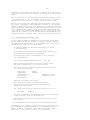
ASEM recognizes the following options:
/INCLUDES:path1[;path2[; ... ;pathn]]
/DEFINE:symbol[:value[:type]]
/OMF-51
/COLUMNS
/QUIET
When the /INCLUDES option is used, the assembler searches the specified
path for include files that cannot be found in the working directory.
The path may be any number of directories separated by ';' characters.
The directories will be searched from left to right.
The path, specified with the /INCLUDES option, is searched before the
path, defined with the (optional) DOS environment variable ASEM51INC!
The /DEFINE option is useful for selecting particular program variants
from the command line that have been implemented with conditional assembly.
It allows to define a symbol with a value and a segment type in the
command line. Value and type are optional. The segment type of the symbol
defaults to NUMBER, if omitted. The symbol value defaults to 0, if omitted.
The symbol value may be any numerical constant. The symbol type must be one
of the following characters:
C
D
I
X
B
N
=
=
=
=
=
=
CODE
DATA
IDATA
XDATA
BIT
NUMBER
(default)
By default, ASEM-51 generates an object file in Intel-HEX format.
When the /OMF-51 option is specified, an absolute OMF-51 module is generated.
Options may be abbreviated as long as they remain unique!
Examples:
0.)
ASEM
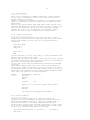
When invoked without parameters, the assembler displays a help screen:
MCS-51 Family Macro Assembler ASEM-51 V1.3
usage:
ASEM <source> [<object> [<listing>]] [options]
options:
1.)
/INCLUDES:path1;path2;path3
/DEFINE:symbol[:value[:type]]
/OMF-51
/COLUMNS
/QUIET
ASEM PROGRAM
will assemble the 8051 assembly language program PROGRAM.A51 and
produce an Intel-HEX file PROGRAM.HEX and a listing PROGRAM.LST.
2.)
ASEM TARZAN.ASM JANE JUNGLE.PRN
will assemble the 8051 assembly language program TARZAN.ASM and
produce an Intel-HEX file JANE.HEX and a listing JUNGLE.PRN.
-103.)
ASEM PROJECT EPROM.
will assemble the 8051 assembly language program PROJECT.A51 and
produce an Intel-HEX file EPROM and a listing PROJECT.LST.
4.)
ASEM ROVER /OMF
will assemble the 8051 assembly language program ROVER.A51 and produce
an absolute OMF-51 object module ROVER.OMF and a listing ROVER.LST.
5.)
ASEM sample COM2: NUL
will assemble the 8051 assembly language program SAMPLE.A51, send
the HEX file output to the serial interface COM2 and suppress the
list file output by sending it to the NUL device.
6.)
ASEM APPLICAT /INC:C:\ASEM51\MCU;D:\MICROS\8051\HEADERS
will assemble the program APPLICAT.A51, while all required include
files will be searched first in the default directory, then in
C:\ASEM51\MCU, and finally in D:\MICROS\8051\HEADERS.
7.)
ASEM UNIVERSL /D:Eva_Board:8000H:C
will assemble the program UNIVERSL.A51, while the CODE symbol
EVA_BOARD will be predefined with value 8000H during assembly.
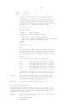
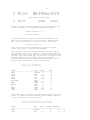
When program errors are detected, they are flagged on the console. This
may look as follows:
MCS-51 Family Macro Assembler ASEM-51 V1.3
APPLICAT.A51(14): must be known on first pass
USERBITS.INC(6): attempt to divide by zero
DEFINES.INC(37): symbol not defined
APPLICAT.A51(20): symbol not defined
APPLICAT.A51(27): no END statement found
5 errors detected
Every error is flagged with the name of the source or include file, the
local line number where it was found, and the error message itself.
This output format makes it easy to integrate ASEM-51 into existing foreign
development environments or workbenches.
A perfect fit for the Turbo C++ IDE (and perhaps others) can be reached
with the /COLUMNS option. When specified, the column numbers of program
errors are output additionally after the line numbers:
MCS-51 Family Macro Assembler ASEM-51 V1.3
APPLICAT.A51(14,12): must be known on first pass
USERBITS.INC(6,27): attempt to divide by zero
DEFINES.INC(37,18): symbol not defined
APPLICAT.A51(20,18): symbol not defined
APPLICAT.A51(27,1): no END statement found
5 errors detected
If errors are detected in macro expansion lines, there is no corresponding
location in the source file. Therefore, the error is flagged with the name
of the source or include file, and the local line number from where the
macro expansion has been invoked. (For callable macros this is the line
with the macro call, and for repeat blocks this is the ENDM line.)
To give the user a hint, the macro name and expansion line (and optionally
column) number are inserted before the actual error message:
-11MCS-51 Family Macro Assembler ASEM-51 V1.3
UARTIO.A51(44,1):
UARTIO.A51(87,1):
UARTIO.A51(87,1):
UARTIO.A51(87,1):
RECEIVE(3,22): segment type mismatch
REPT(4,19): symbol not defined
REPT(8,19): symbol not defined
REPT(12,19): symbol not defined
4 errors detected
The expansion line number is the number of the expansion line within the
corresponding macro expansion, starting with 1. If the error occurs during
expansion of a repeat block, the keyword REPT replaces the macro name.
The /QUIET option suppresses all console output except error messages.
When terminating, ASEM-51 returns an exit code to the operating system:
situation
ERRORLEVEL
---------------------------------------------no errors
0
program errors detected
1
fatal runtime error
2
Note: Warnings do not influence the exit code!
II.1.4 DOS Environment
---------------------To specify a search path for include files, an optional environment variable
ASEM51INC can be defined:
SET ASEM51INC=<path>
<path> may be any number of directories separated by ';' characters.
Be sure that the whole definition doesn't contain any blanks or tabs!
If ASEM51INC is defined, the assembler searches the specified <path> for
include files that can neither be found in the working directory, nor in
the search path specified with the /INCLUDES option.
The <path> directories will be searched from left to right.
Examples:
1.)
SET ASEM51INC=C:\ASEM51\MCU;D:\MICROS\MCS51\INCL
If include files can neither be found in the working directory,
nor in the /INCLUDES path (if specified), the assembler searches
next C:\ASEM51\MCU and finally D:\MICROS\MCS51\INCL.
2.)
SET ASEM51INC=C:\ASEM51\MCU;%PATH%
If ASEM51INC is defined as above in AUTOEXEC.BAT after the PATH
statement, the assembler finally searches the directory C:\ASEM51\MCU
and then all the directories, contained in the DOS program search
path, from left to right!
The maximum length of <path> is limited to 255 characters. This cannot be
exceeded with the SET command of the DOS command interpreter COMMAND.COM,
but with third party command interpreters like 4DOS (max. 512 characters)!
Note that trailing blanks and tabs behind the names of environment variables
seem to be considered significant under MS-DOS! If one subsequently defines
and
SET ASEM51INC =C:\ASEM51\MCU
SET ASEM51INC=C:\8051\MCU
there will be two (!) entries concurrently in the
the assembler will recognize the second one only.
trailing blanks and tabs from variable names, the
either! That is why you should be sure, to always
variable without blanks and tabs.
DOS environment! However,
Since DOS doesn't truncate
assembler can't do this
define the environment
-12II.1.5 Running ASEM-51 in the Borland-IDE
----------------------------------------Turbo C++ (1.0 thru 3.0) users will appreciate the possibility to invoke
ASEM-51 as a transfer program from the Borland IDE.
For this, the filter program ASEM2MSG for the ASEM-51 error messages
has been provided. To integrate ASEM-51 into the Borland IDE, perform
the following steps:
- Be sure that ASEM-51 has been installed properly as described before,
or that ASEM.EXE and ASEM2MSG.EXE are somewhere in your PATH.
- Start the Turbo C++ (or Borland C++) IDE for DOS.
- For Turbo C++ 1.0, first click: Options | Full menus | ON
- Click from the menu bar:
Options | Transfer
- When the "Transfer" dialog box is active, press the Edit button.
- Now the "Modify/New Transfer Item" dialog box should be active.
Fill in the following items:
Program Title:
Program Path:
Command Line:
Translator:
Hot key:
ASEM-~51
ASEM
$NOSWAP $SAVE CUR $CAP MSG(ASEM2MSG) $EDNAME /C
[X]
Shift F8
Then press the New button.
- When returned to the "Transfer" dialog box, press the OK button.
- Click from the menu bar:
Options | Save | OK
Now it should be possible, to assemble the file in the active edit
window with ASEM-51, when pressing Shift-F8. The error messages (if any)
should appear in the "Message" window. You can browse through the errors,
and jump into the source text by simply pressing <Enter>. This even works,
if the error is not in the program itself, but in an include file!
Turbo-Pascal 7.0 users can also employ their Borland IDE for assembly.
To integrate ASEM-51 into the Turbo-Pascal IDE, perform the following
steps:
- Be sure that ASEM-51 has been installed properly as described before,
or that ASEM.EXE and ASEM2MSG.EXE are somewhere in your PATH.
- Start the Turbo-Pascal 7.0 (or Borland-Pascal 7.0) IDE for DOS.
- Click from the menu bar:
Options | Tools
- When the "Tools" dialog box is active, press the New button.
- Now the "Modify/New Tool" dialog box should be active.
Fill in the following items:
Title:
Program path:
Command line:
Hot keys:
ASEM-~5~1
ASEM
$NOSWAP $SAVE CUR $CAP MSG(ASEM2MSG) $EDNAME
Shift+F8
Then press the OK button.
- When returned to the "Tools" dialog box, press the OK button.
- Click from the menu bar:
Options | Environment | Preferences
- When the "Preferences" dialog box is active, disable the "Close on
go to source" item in the "Options" checkbox. Then press the OK button.
- Finally click from the menu bar: Options | Save
-13Now ASEM-51 can be invoked with Shift-F8, to assemble the program in the
active edit window, while error messages (if any) appear in the "Messages"
window.
Users of both Turbo C++ and Turbo-Pascal should prefer the Turbo C++ IDE.
In the Turbo-Pascal 7.0 IDE, the /COLUMNS (or /C) option has no effect!
Turbo-Pascal versions prior to 7.0 didn't implement the Tools menu.
Note that the transfer macro $SAVE CUR saves the contents of the active
edit window (if modified), before ASEM.EXE is invoked! If your assembler
program includes further source files (which may be currently loaded into
other edit windows), better specify $SAVE ALL. This will save the contents
of all (modified) edit windows to disk files, before invoking ASEM.EXE!
If you are not sure, specify $SAVE PROMPT. This will prompt you for every
(modified) edit window to save the contents before running ASEM.EXE. For
further information on transfer macros, refer to the Borland online help!
II.1.6 Running ASEM-51 from Windows 3.1x
---------------------------------------Of course ASEM and ASEMX are running fine in the Windows 3.1x DOS-Box!
But for integration into the Windows 3.1x desktop, the files ASEM.PIF
and ASEM.ICO have been provided. To insert ASEM-51 into a group of the
Program Manager, perform the following steps:
- Be sure that ASEM-51 has been installed properly for MS-DOS
as described before.
- Start Windows 3.1x and expand the Program Manager window to its
full screen size representation, if necessary.
- Focus the program group in which ASEM-51 is to be inserted,
e.g. "Applications".
- Click from the Program Manager menu bar:
File | New
- When the "New Program Object" dialog box is active, choose
the option "Program Item", and click the OK button.
- Now the "Program Item Properties" dialog box should be active.
Fill in the following items:
Description:
Command Line:
Working Directory:
Shortcut Key:
Run Minimized:
ASEM-51
ASEM.PIF
(whatever you want)
(whatever you want)
[ ]
Then press the [Change Icon] button.
- Now a message box appears with the error message
"There are no icons available for the specified file".
Simply press the OK button.
- The "Change Icon" dialog box should be displayed now. Fill in
File Name:
ASEM.ICO
and press the OK button. Now the ASEM-51 icon should be displayed
in the icon field. Press the OK button again.
- When returned to the "Program Item Properties" dialog box, press
the OK button.
(In national Windows versions, things may look slightly different.)
Now ASEM.EXE can be invoked by simply double-clicking the ASEM-51 icon.
After entering the program parameters in a corresponding dialog box,
ASEM is running in a DOS window, which remains open after program
termination, to let you have a look on the error messages.
-14In principle, the installation of the protected-mode assembler ASEMX.EXE
can also be done as described above. However, the <Description> field
should be filled with "ASEM-51 XMS", the <Command Line> should be
"ASEMX.PIF", and the icon <File Name> should be ASEMX.ICO instead.
II.1.7 Running ASEM-51 from BRIEF
--------------------------------BRIEF 3.x users can integrate ASEM-51 into their editor by simply
defining another DOS environment variable in their AUTOEXEC.BAT with
SET BCA51="ASEM %%s"
This specifies the command for compiling files with extension *.A51.
After that, ASEM-51 can be invoked from BRIEF with Alt-F10.
II.1.8 The DOS Protected-Mode Assembler ASEMX
--------------------------------------------In general, the proven real-mode assembler ASEM.EXE is sufficient also
for very large programs. Nevertheless, it may be running out of memory,
if a program contains a huge number of long user-defined symbols, or lots
of large macro definitions.
To close the gap, the ASEM-51 package includes the new protected-mode
assembler ASEMX.EXE. ASEMX is functionally identical to ASEM, but it can
use extended memory, to meet extreme workspace requirements.
ASEMX is accompanied by Borland's 16-bit DPMI server DPMI16BI.OVL and
runtime manager RTM.EXE. It requires a 286 CPU (or better), and at least
512 kB of free XMS memory (1 MB recommended)!
When ASEMX is invoked, DPMI16BI.OVL and RTM.EXE must be either
- in your default directory,
- where ASEMX.EXE is, or
- somewhere in your PATH
During startup, the DPMI server tries to allocate all the remaining free
XMS memory for use by ASEMX. If you don't want this, you can restrict the
amount of allocated memory with the DOS environment variable DPMIMEM:
SET DPMIMEM=MAXMEM n
will restrict the XMS memory space, used for the DPMI interface, to n kB.
Never set n to a value greater than 16383!!!
In general, the Borland DPMI interface is very reliable and does normally
not conflict with other memory managers. ASEMX will also run with other
versions of DPMI16BI.OVL and RTM.EXE provided with various Borland software
packages (except TC++ 3.0 and BC++ 3.1).
However, there is trouble ahead on systems with more than 16 MB RAM!
Without specific installation, there is a fatal tendency to crash, hang,
or even boot, whenever a DPMI program like ASEMX is invoked.
For proper operation of the DPMI interface, MS-DOS 5.0 (or later) is
required, and EMM386.EXE must be loaded!
If EMM386.EXE has been loaded with parameters (e.g. NOEMS), the Borland
16-bit DPMI server cannot handle more than 16 MB! However, without
parameters (i=nnnn, x=nnnn are o.k.) or with other DPMI servers there may
be more. In these cases, ASEMX can use up to 64 MB of extended memory!
If ASEMX is running in a system environment with an own DPMI server, e.g.
the Windows DOS-Box, RTM.EXE will detect this and use the active DPMI server
instead of DPMI16BI.OVL. In this case, the environment variable DPMIMEM has
no effect.
To restrict (or increase) the available XMS memory for the Windows 3.1x DOS
prompt, change file DOSPRMPT.PIF in your WINDOWS directory with the Windows
PIF file editor.
For further information on how to make more or less XMS memory available
to application programs in other system environments, see the corresponding
user manuals.
Another interesting alternative is the Borland 32-bit DPMI server with
virtual memory management. It cannot be provided with the ASEM-51 package
-15for license reasons, but is contained in Borland's Turbo-Assembler 4.0
and 5.0, Borland C++ 4.5x and 5.0x, and maybe others. It has originally been
developed for the Borland command line tools, but it also works with ASEMX.
It requires a 386 CPU (or better), and allows to extend the free physical
memory with a swap file that can be created with the program MAKESWAP.EXE.
Apart of that, the 32-bit DPMI server DPMI32VM.OVL and the runtime manager
32RTM.EXE are required.
The batch file ASEM32.BAT, provided with the ASEM-51 package, shows how to
run ASEMX with 64 MB of virtual memory, using Borland's 32-bit DPMI server.
II.1.9 The Win32 Console-Mode Assembler ASEMW
--------------------------------------------In principle, the DOS assemblers ASEM and ASEMX are also running in the
Windows 9x/NT/2000/XP DOS-Box, but with some typical DOS-specific limitations:
file names are restricted to the 8.3 format, path strings are limited to
64 characters, the real-mode assembler cannot access more than 640 kB RAM,
and so on.
To overcome these disadvantages, the ASEM-51 package comes with the new
Win32 console-mode assembler ASEMW.EXE. ASEMW is functionally identical
to ASEM, but it can handle long file names and benefits of the Win32
memory management, which allows to assemble astronomically large programs!
Hint: If you love file names with blanks in the middle, you have to
enclose them in double quotes, e.g.
ASEMW "Test-Program for my 80C32 Evaluation-Board.a51"
II.1.10 The HEXBIN Utility
-------------------------Most EPROM programmers are accepting the Intel-HEX object file format that
is output by ASEM-51. However, for dumb EPROM burners and special purposes
it might be useful to convert the HEX file to a pure binary image file.
For this the conversion utility HEXBIN is provided.
It is invoked as follows:
HEXBIN <hex> [<bin>] [/OFFSET:o] [/LENGTH:l] [/FILL:f] [/QUIET]
where <hex> is the input file in Intel-HEX format, and <bin> is the
binary output file. The parameter <bin> is optional. When omitted, the
file name is derived from the <hex> file name, but with the extension BIN.
All file names may be specified without extensions. In these cases, the
program adds default extensions as shown below:
file
extension
-----------------------------<hex>
.HEX
<bin>
.BIN
If you want a file name to have no extension, terminate it with a '.'!
Instead of file names you may also specify device names to redirect the
output to character I/O ports. Device names may be terminated with a ':'!
It is not checked, whether the device is existing or suitable for the task.
The binary file output can also be controlled with the options /OFFSET,
/FILL and /LENGTH.
Normally the first byte in the binary file is the first byte of the HEX
record with the lowest load address. If a number of dummy bytes is to be
inserted on top of the file (e.g. for alignment in an EPROM image), this
can be performed with the /OFFSET option:
/OFFSET:1000
would insert 4096 dummy bytes before the first byte of the first HEX record
loaded. The offset must always be specified as a hex number. The default
offset is 0.
Since there may be peepholes between the HEX records, a fill byte value can
be defined with the /FILL option:
/FILL:0
-16would fill all peepholes between the HEX records with zero bytes as well as
all the dummy bytes that might have been inserted with the /OFFSET or /LENGTH
option. The fill byte value must always be specified as a hex number.
The default fill byte is the EPROM-friendly FFH.
By default the last byte in the binary file is the last byte of the HEX
record with the highest load address. If the binary file should have a
well defined length, then a number of dummy bytes can be appended to the
file (e.g. for exactly matching an EPROM length), this can be performed
with the /LENGTH option:
/LENGTH:8000
would append as many dummy bytes behind the last byte of the file, that the
total file length becomes exactly 32768 bytes. The file length must always
be specified as a hex number.
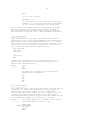
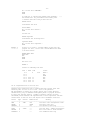
When HEXBIN has been invoked with all the above options, it may display a
file conversion report like this:
Hex File Converter HEXBIN V2.3
offset:
first address:
last address:
fill peepholes with:
binary image length:
1000H bytes
9000H
A255H
00H
8000H bytes
The /QUIET option suppresses this console output, while error messages are
displayed regardless.
Options may be abbreviated as long as they remain unique!
Examples:
0.)
HEXBIN
When invoked without parameters, HEXBIN displays a help screen:
Hex File Converter HEXBIN V2.3
1.)
usage:
HEXBIN <hexfile> [<binary>] [options]
options:
/OFFSET:offset
/LENGTH:length
/FILL:fillbyte
/QUIET
HEXBIN PROGRAM
will convert the Intel-HEX file PROGRAM.HEX to a pure binary image file
PROGRAM.BIN.
2.)
HEXBIN TARZAN.OBJ JUNGLE/FILL:E5
will convert the Intel-HEX file TARZAN.OBJ to a binary image file
JUNGLE.BIN and fill all peepholes between the HEX file records with
the binary value E5H.
3.)
HEXBIN PROJECT EPROM. /off:8000 /length:10000 /f:0
will convert the Intel-HEX file PROJECT.HEX to a binary image file
EPROM, insert 32K dummy bytes on top of file, fill all peepholes
and the dummy bytes with nulls, and extend the file to exactly 64K.
When terminating HEXBIN returns an exit code to the operating system:
situation
ERRORLEVEL
---------------------------------------------no errors
0
conversion errors detected
1
fatal runtime error
2
-17There is also a Win32 console-mode version of HEXBIN: HEXBINW.EXE!
HEXBINW is functionally identical to HEXBIN, but can handle long file names.
II.2 Linux Implementation
------------------------Until version 1.2, ASEM-51 was available for MS-DOS only.
To get rid of the original DOS "look and feel", many interfaces to the
operating system had to be modified or rewritten, e.g. command line
processing, console I/O, file handling, UNIX environment, and memory
management. Furthermore, the general behaviour of the programs had to be
adapted to UNIX conventions.
A certain rest of DOS flavour may still be remaining though.
On the other hand, the Linux binaries are able to read ASCII files in both
DOS and UNIX format. However, ASCII files are always written in UNIX format.
All these differences make it necessary to describe the Linux implementation
in a separate section!
II.2.1 Files
-----------Your ASEM-51 distribution archive for Linux should contain the following
groups of files:
1.) asem_51.doc
docs.htm
*.htm
*.gif
*.jpg
asem
asem.1
hexbin
hexbin.1
demo.a51
*.mcu
ASEM-51 User's Manual, ASCII format
index file of the ASEM-51 documentation, HTML format
further pages of the HTML documentation
GIF images referenced by HTML pages
JPEG images referenced by HTML pages
assembler (Linux 386)
man-page for asem
hex-to-binary conversion utility (Linux 386)
man-page for hexbin
a sample 8051 assembler program
processor definition files of 8051 derivatives
(for a detailed list of MCU files see chapter
"VI. Support of 8051 Derivatives")
2.)
boot51.doc
boot51.htm
boot51.a51
customiz
customiz.1
boot
boot.1
upload
upload.new
reset51
reset51.1
blink.a51
BOOT-51 User's Manual, ASCII format
index file of the BOOT-51 documentation, HTML format
BOOT-51 assembler source (for ASEM-51 V1.3 and up)
BOOT-51 customization utility (Linux 386)
man-page for customiz
shell script for application program upload
man-page for boot
called by boot only (generic version)
"new" upload (optimized for stty 2.0 or later)
program to reset the target system via PC ports
man-page for reset51
sample test program for BOOT-51
3.)
README.1ST
license.doc
release.130
support.doc
install.sh
uninst51.sh
quick information, ASCII format
ASEM-51 License Agreement, ASCII format
ASEM-51 Release Notes, ASCII format
ASEM-51 Support Guide, ASCII format
creates a proper ASEM-51 installation under Linux
deletes all files of the ASEM-51 package (Linux)
II.2.2 Installation under Linux
------------------------------ASEM-51 for Linux is available as a tar archive and an rpm package.
If you have got the rpm package, login as root and simply type
rpm -i asem51-1.3-1.i386.rpm
The rpm package has been tested on S.u.S.E.-Linux only, but should also
work on other Linux distributions that meet the FHS directory standard.
If you have got the tar archive, perform the following steps:
gzip -d asem51-1.3-ELF.tar.gz
-18tar xvf asem51-1.3-ELF.tar
cd asem51
sh install.sh
If you are installing ASEM-51 as root (preferred), the installation script
install.sh will install the whole package in /usr/local/share/asem-51/1.3,
and establish some symbolic links in /usr/local/bin and /usr/local/man/man1.
If you are installing ASEM-51 under another user-id, install.sh tries to
install the software in your home directory under ~/asem-51/1.3, and
establish some symbolic links in ~/bin and ~/man/man1.
For details see the messages, install.sh is displaying on the console,
and do some fine-tuning accordingly:
If you haven't installed ASEM-51 as root, it may be necessary to add
~/bin to your PATH, and ~/man to your MANPATH.
To specify a search path for the include files *.mcu provided, you can
define an optional environment variable ASEM51INC.
For this, bash, ksh, and sh users should insert the following lines into
their .profile file:
ASEM51INC=/usr/local/share/asem-51/1.3/mcu
export ASEM51INC
csh, tcsh, and zsh users should insert the following line into their
.login file respectively:
setenv ASEM51INC /usr/local/share/asem-51/1.3/mcu
If you have installed ASEM-51 in your home directory, ASEM51INC should
point to ~/asem-51/1.3/mcu of course.
To read the HTML manuals, invoke your web browser and bookmark the index page
/usr/local/share/asem-51/1.3/html/docs.htm
~/asem-51/1.3/html/docs.htm
(installation as root)
(local installation)
Note that you cannot reset your 8051 target system with a PC printer port,
if you haven't installed ASEM-51 as root!
(For details see the BOOT-51 documentation provided.)
If you have installed ASEM-51, but you don't like it, you can easily
uninstall it. If you have installed the rpm package, simply type
rpm -e asem51
If you have installed the generic tar archive, be sure to uninstall
ASEM-51 under the same user-id you previously used for installation! Run
uninst51.sh
and that's it.
II.2.3 Linux Command Line Operation
----------------------------------Under Linux, the assembler is invoked by typing:
asem [<options>] <source> [<object> [<listing>]]
where <source> is the 8051 assembler source, <object> is the output
file, and <listing> is the assembler list file.
All file names that are specified explicitly, are left unchanged.
The parameters <object> and <listing> are optional. When omitted, the
<object> file name is derived from the <source> file name, but with
extension ".hex" (or ".omf"). When the <listing> file name is omitted,
it is derived from the <object> file name, but with extension ".lst":
file
extension
-----------------------------------------------
-19<object>
<listing>
.hex
.lst
(with -o option: .omf)
Instead of file names you may also specify device names to redirect the
output to I/O devices. Device names are assumed to start with "/dev/".
Of course no extensions will be added to device names!
It is not checked, whether the device is existing or suitable for the task.
Although it is possible to read the source file from a character device
instead of a file, this cannot be recommended: Since ASEM-51 is a two-pass
assembler, it always reads the source file twice!
The maximum length of a file parameter is limited to 255 characters!
asem recognizes the following options:
short options
| long options
--------------------------+--------------------------------i path1:path2:path3
| --includes=path1:path2:path3
-d symbol[:value[:type]] | --define=symbol[:value[:type]]
-o
| --omf-51
-c
| --columns
-v
| --verbose
The short and long options in the same row are equivalent.
Long options may be abbreviated as long as they remain unique.
All option names are case-sensitive!
When the --includes option is used, the assembler searches the specified
path for include files that cannot be found in the working directory.
The path may be any number of directories separated by ':' characters.
The directories will be searched from left to right.
The path, specified with the --includes option, is searched before the
path, defined with the (optional) environment variable ASEM51INC!
The maximum path length is limited to 255 characters.
The --define option is useful for selecting particular program variants
from the command line that have been implemented with conditional assembly.
It allows to define a symbol with a value and a segment type in the
command line. Value and type are optional. The segment type of the symbol
defaults to NUMBER, if omitted. The symbol value defaults to 0, if omitted.
The symbol value may be any numerical constant. The symbol type must be one
of the following characters:
C
D
I
X
B
N
=
=
=
=
=
=
CODE
DATA
IDATA
XDATA
BIT
NUMBER
(default)
By default, ASEM-51 generates an object file in Intel-HEX format. When
the --omf-51 option is specified, an absolute OMF-51 module is generated.
Examples:
0.)
asem
When invoked without parameters, the assembler displays a help screen:
MCS-51 Family Macro Assembler ASEM-51 V1.3
1.)
usage:
asem [options] <source> [<object> [<listing>]]
options:
-i
-d
-o
-c
-v
--includes=path1:path2:path3
--define=symbol[:value[:type]]
--omf-51
--columns
--verbose
asem program.a51
will assemble the 8051 assembly language program program.a51 and
produce an Intel-HEX file program.hex and a listing program.lst.
-202.)
asem tarzan.asm jane jungle.prn
will assemble the 8051 assembly language program tarzan.asm and
produce an Intel-HEX file jane and a listing jungle.prn.
3.)
asem project eprom
will assemble the 8051 assembly language program project and
produce an Intel-HEX file eprom and a listing eprom.lst.
4.)
asem -o rover.a51
will assemble the 8051 assembly language program rover.a51 and produce
an absolute OMF-51 object module rover.omf and a listing rover.lst.
5.)
asem sample.a51 /dev/ttyS0 /dev/null
will assemble the 8051 assembly language program sample.a51, send
the HEX file output to the serial interface /dev/ttyS0 and suppress
the list file output by sending it to the /dev/null device.
6.)
asem -i /usr/local/include/asem-51:~/8051/inc app.a51
will assemble the program app.a51, while all required include
files will be searched first in the default directory, then in
/usr/local/include/asem-51, and finally in ~/8051/inc.
7.)
asem --define=Eva_Board:8000H:C universal.a51
will assemble the program universal.a51, while the CODE symbol
EVA_BOARD will be predefined with value 8000H during assembly.
When program errors are detected, corresponding error messages are output
to standard error. This may look as follows:
applicat.a51(14): must be known on first pass
userbits.inc(6): attempt to divide by zero
defines.inc(37): symbol not defined
applicat.a51(20): symbol not defined
applicat.a51(27): no END statement found
Every error is flagged with the name of the source or include file, the
local line number where it was found, and the error message itself.
This output format provides a hook to run ASEM-51 from third-party IDEs.
A perfect fit may be reached with the --columns option. When specified,
the column numbers of program errors are output additionally after the
line numbers:
applicat.a51(14,12): must be known on first pass
userbits.inc(6,27): attempt to divide by zero
defines.inc(37,18): symbol not defined
applicat.a51(20,18): symbol not defined
applicat.a51(27,1): no END statement found
If errors are detected in macro expansion lines, there is no corresponding
location in the source file. Therefore, the error is flagged with the name
of the source or include file, and the local line number from where the
macro expansion has been invoked. (For callable macros this is the line
with the macro call, and for repeat blocks this is the ENDM line.)
To give the user a hint, the macro name and expansion line (and optionally
column) number are inserted before the actual error message:
uartio.a51(44,1):
uartio.a51(87,1):
uartio.a51(87,1):
uartio.a51(87,1):
RECEIVE(3,22): segment type mismatch
REPT(4,19): symbol not defined
REPT(8,19): symbol not defined
REPT(12,19): symbol not defined
-21-
The expansion line number is the number of the expansion line within the
corresponding macro expansion, starting with 1. If the error occurs during
expansion of a repeat block, the keyword REPT replaces the macro name.
By default, ASEM-51 is totally "quiet", if no errors are detected.
If the --verbose option is specified, additional product, version, and
error summary information is written to standard output:
MCS-51 Family Macro Assembler ASEM-51 V1.3
uartio.a51(44,1):
uartio.a51(87,1):
uartio.a51(87,1):
uartio.a51(87,1):
RECEIVE(3,22): segment type mismatch
REPT(4,19): symbol not defined
REPT(8,19): symbol not defined
REPT(12,19): symbol not defined
4 errors detected
When terminating, ASEM-51 returns an exit code to the calling process:
situation
exit code
--------------------------------------------no errors
0
program errors detected
1
fatal runtime error
2
Note: Warnings are also output on standard error,
but do not influence the exit code!
II.2.4 Linux Environment
-----------------------To specify a search path for include files, an optional environment variable
ASEM51INC can be defined:
1.) For bash, ksh, and sh:
ASEM51INC=<path>
export ASEM51INC
2.) For csh, tcsh, and zsh:
setenv ASEM51INC <path>
<path> may be any number of directories separated by ':' characters.
Be sure that the whole definition doesn't contain any blanks or tabs!
If ASEM51INC is defined, the assembler searches the specified <path> for
include files that can neither be found in the working directory, nor in
the search path specified with the --includes option.
The <path> directories will be searched from left to right.
Examples:
1.) bash:
ASEM51INC=/usr/local/include/asem-51:~/micros/mcs51/inc
export ASEM51INC
If include files can neither be found in the working directory,
nor in the --includes path (if specified), the assembler searches
next /usr/local/include/asem-51 and finally ~/micros/mcs51/inc.
2.) csh:
setenv ASEM51INC /usr/local/include/asem-51
If ASEM51INC is defined as above in .login, the assembler finally
searches the directory /usr/local/include/asem-51 for include files.
The maximum length of <path> is limited to 255 characters.
-22II.2.5 The HEXBIN Utility
------------------------Most EPROM programmers are accepting the Intel-HEX object file format that
is output by ASEM-51. However, for dumb EPROM burners and special purposes
it might be useful to convert the HEX file to a pure binary image file.
For this the conversion utility hexbin is provided.
It is invoked as follows:
hexbin [<options>] <hexfile> [<binary>]
where <hexfile> is the input file in Intel-HEX format, and <binary> is the
binary output file. All file names that are specified explicitly, are left
unchanged. The parameter <binary> is optional. When omitted, the file name
is derived from the <hexfile>, but with the extension ".bin".
The maximum length of a file parameter is limited to 255 characters!
Instead of file names you may also specify device names to redirect the input
or output to I/O devices. Device names are assumed to start with "/dev/".
Of course no extensions will be added to device names!
It is not checked, whether the device is existing or suitable for the task.
hexbin recognizes the following options:
short options | long options
---------------+---------------------o <offset>
| --offset=<offset>
-l <length>
| --length=<length>
-f <fillbyte> | --fill=<fillbyte>
-v
| --verbose
The short and long options in the same row are equivalent.
Long options may be abbreviated as long as they remain unique.
All option names are case-sensitive!
The binary file output can be controlled with the options --offset,
--fill and --length.
Normally the first byte in the binary file is the first byte of the HEX
record with the lowest load address. If a number of dummy bytes is to be
inserted on top of the file (e.g. for alignment in an EPROM image), this
can be performed with the --offset option:
--offset=1000
would insert 4096 dummy bytes before the first byte of the first HEX record
loaded. The offset must always be specified as a hex number. The default
offset is 0.
Since there may be peepholes between the HEX records, a fill byte value can
be defined with the --fill option:
--fill=0
would fill all peepholes between the HEX records with zero bytes as well
as all the dummy bytes that might have been inserted with the --offset or
--length option. The fill byte value must always be specified as a hex
number. The default fill byte is the EPROM-friendly FFH.
By default the last byte in the binary file is the last byte of the HEX
record with the highest load address. If the binary file should have a
well defined length, then a number of dummy bytes can be appended to the
file (e.g. for exactly matching an EPROM length), this can be performed
with the --length option:
--length=8000
would append as many dummy bytes behind the last byte of the file, that the
total file length becomes exactly 32768 bytes. The file length must always
be specified as a hex number.
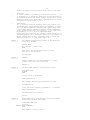
By default, hexbin is totally "quiet", if no errors are detected.
If the --verbose option is specified, additional product and version
information, and a file conversion report is written to standard output:
-23Hex File Converter HEXBIN V2.3
offset:
first address:
last address:
fill peepholes with:
binary image length:
FF0H bytes
7FF0H
8255H
A5H
2000H bytes
Examples:
0.)
hexbin
When invoked without parameters, hexbin displays a help screen:
Hex File Converter HEXBIN V2.3
usage:
options:
1.)
hexbin [options] <hexfile> [<binary>]
-o
-l
-f
-v
--offset=<offset>
--length=<length>
--fill=<fillbyte>
--verbose
hexbin program.hex
will convert the Intel-HEX file program.hex to a pure binary image file
program.bin.
2.)
hexbin -f E5 tarzan.obj jungle.bin
will convert the Intel-HEX file tarzan.obj to a binary image file
jungle.bin and fill all peepholes between the HEX file records with
the binary value E5H.
3.)
hexbin --off=8000 -l10000 --fill=0 project.hex eprom
will convert the Intel-HEX file project.hex to a binary image file
eprom, insert 32K dummy bytes on top of file, fill all peepholes
and the dummy bytes with nulls, and extend the file to exactly 64K.
When terminating hexbin returns an exit code to the calling process:
situation
exit code
--------------------------------------------no errors
0
conversion errors detected
1
fatal runtime error
2
II.3 The DEMO Program
--------------------For getting started with a new assembler, it is always helpful to have
a program that can be assembled with it. For this purpose, the 8051
assembler program DEMO.A51 is provided, which can be used for a first
test of the ASEM-51 installation. For this, you should either have installed
ASEM-51 as described above, or keep all files of the ASEM-51 package directly
in your working directory!
Under MS-DOS or in a Windows DOS-Box simply type
ASEM DEMO
HEXBIN DEMO
at the DOS prompt. ASEM and HEXBIN should finish without errors and you
should have the following new files on your disk:
DEMO.HEX
DEMO.LST
DEMO.BIN
Intel-HEX file
assembler list file of DEMO.A51
binary image file of DEMO.HEX
-24Under Linux type
asem demo.a51
hexbin demo.hex
Again asem and hexbin should finish without errors and you should have
the following new files on your disk:
demo.hex
demo.lst
demo.bin
Intel-HEX file
assembler list file of demo.a51
binary image file of demo.hex
If something goes wrong, either ASEM-51 is not properly installed, there
may be files missing in your distribution, or the assembler simply cannot
find the include file 8052.mcu!
demo.a51 may also serve as a sample assembler program that includes examples
for (nearly) all machine instructions, pseudo instructions, assembler
controls, and meta instructions that have been implemented in ASEM-51.
Whenever in doubt how to use a particular command, demo.a51 may be a
valuable help.
Unlike other assemblers, the ASEM-51 list file is no alibi feature!
It is really instructive to compare the original source to the generated
code in the listing.
-25-
III. The ASEM-51 Assembly Language
==================================
The user should be familiar with 8051 microcontrollers and assembly
language programming. This manual will not explain the architecture of
the MCS-51 microcontroller family nor will it discuss the basic concepts
of assembly language programming. It only describes the general syntax
of assembler statements and the assembler instructions that have been
implemented in ASEM-51.
III.1 Statements
---------------Source files consist of a sequence of statements of one of the forms:
[symbol:] [instruction [arguments]]
symbol
$control
instruction argument
[(argument)]
[;comment]
[;comment]
[;comment]
Everything that is written in brackets is optional.
The maximum length of source code lines is 255 characters.
Everything from the ';' character to the end of line is assumed to be
commentary. Blank lines are considered to be commentary, too.
The lexical elements of a statement may be separated by blanks and tabs.
Aside of character string constants, upper and lower case letters are
equivalent.
Examples:
HERE:
MOV A,#0FFH
;define label HERE and load A with FFH
YEAR EQU 1999
;define symbol for current year
$INCLUDE (80C517.MCU)
;include SAB80C517 register definitions
III.2 Symbols
------------Symbols are user-defined names for addresses, numbers or macros.
Their maximum significant length is 31 characters. They can be even
longer, but everything behind the first 31 characters is ignored.
Symbols may consist of letters, digits, '_' and '?' characters.
A symbol name must not start with a digit!
Upper and lower case letters are considered to be equivalent.
Note: Assembly language keywords must not be redefined as user symbols!
Example:
Is_this_really_a_SYMBOL_?
is a legal symbol name!
-26-
III.3 Constants
--------------Numeric constants consist of a sequence of digits, followed by a radix
specifier. The first character must always be a decimal digit.
The legal digits and radix specifiers are:
constant
digits
radix
-----------------------------------binary
0 ... 1
B
octal
0 ... 7
Q or O
decimal
0 ... 9
D or none
hex
0 ... F
H
Thus, for example, the following constants are equivalent:
1111111B
177Q
177o
127
127d
07FH
binary
octal
octal
decimal
decimal
hex
Character constants may be used wherever a numeric value is allowed.
A character constant consists of one or two printing characters enclosed
in single or double quotes. The quote character itself can be represented
by two subsequent quotes. For example:
'X'
"a@"
''''
8 bit constant:
16 bit constant:
8 bit constant:
58H
6140H
27H
In DB statements, character constants may have any length.
In this case, we call it a character string. For example:
'This is only text!'
-27-
III.4 Expressions
----------------Arithmetic expressions are composed of operands, operators and parentheses.
Operands may be user-defined symbols, constants or special assembler symbols.
All operands are treated as unsigned 16-bit numbers.
Special assembler symbols, that can be used as operands are:
AR0, ... , AR7
direct addresses of registers R0 thru R7
$
the location counter of the currently active segment
(start address of the current assembler statement)
The following operators are implemented:
Unary operators:
+
NOT
HIGH
LOW
Binary operators: +
*
/
MOD
SHL
SHR
AND
OR
XOR
.
EQ
NE
LT
LE
GT
GE
identity:
+x = x
two's complement:
-x = 0-x
one's complement: NOT x = FFFFH-x
high order byte
low order byte
unsigned addition
unsigned subtraction
unsigned multiplication
unsigned division
unsigned remainder
logical shift left
logical shift right
logical and
logical or
exclusive or
bit operator used for bit-adressable locations
or = equal to
----.
or <> not equal to
| results are:
or < less than
|
or <= less or equal than
|
0 if FALSE
or > greater than
| FFFFH if TRUE
or >= greater or equal than ____|
Operators that are no special characters but keywords as SHR or AND must
be separated from their operands by at least one blank or tab.
In general expressions are evaluated from left to right according to
operator precedence, which may be overridden by parentheses.
Parentheses may be nested to any level.
Expressions always evaluate to unsigned 16-bit numbers, while overflows
are ignored. When an expression result is to be assigned to an 8-bit
quantity, the high byte must be either 00 or FF.
Operator precedence:
----------------------------------------------------------------( )
^ highest
+ - NOT HIGH LOW
(unary)
|
.
|
* / MOD
|
SHL SHR
|
+ (binary)
|
EQ = NE <> LT < LE <= GT > GE >=
|
AND
|
OR XOR
v lowest
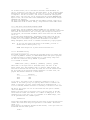
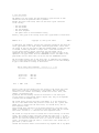
----------------------------------------------------------------Example: The expression P1.((87+3)/10 AND -1 SHR 0DH) will evaluate to 91H.
-28-
III.5 The 8051 Instruction Set
-----------------------------ASEM-51 implements all 8051 machine instructions including generic jumps
and calls. The assembler implements two instructions
JMP <address>
CALL <address>
that do not represent a specific opcode: generic jump and call.
These instructions will always evaluate to a jump or call, not necessarily
the shortest, that will reach the specified address.
JMP may assemble to SJMP, AJMP or LJMP, while CALL can only evaluate to
ACALL or LCALL. Note that the assembler decision may not be optimal. For
code addresses that are forward references, the assembler always generates
LJMP or LCALL respectively. However, for backward references this is a
powerful tool to reduce code size without extra trouble.
With the $PHILIPS control, ASEM-51 can be switched to the reduced instruction
set of the Philips 83C75x family of microcontrollers. This disables the LJMP,
LCALL, and MOVX instructions as well as the XDATA and XSEG pseudo instructions,
and generic jumps and calls will always assemble to absolute addressing.
The rest of the 8051 instruction mnemonics is listed in Appendix D.
Appendices I and J are containing tables of all 8051 instructions with
their opcodes, mnemonics, arguments, lengths, affected flags and durations.
The comprehensive example program DEMO.A51 provided shows all the 8051
instructions in a syntactical context.
For detailed information on the Intel MCS-51 architecture and instruction
set refer to the HTML documentation file MCS51MAN.HTM provided.
(Requires a web-browser and full Internet access!)
All MCS-51 instruction mnemonics are copyright (c) by Intel Corporation!
-29-
III.6 Pseudo Instructions
------------------------In the subsequent paragraphs, all ASEM-51 pseudo instructions are described.
Lexical symbols are written in lower case letters, while assembler keywords
are written in upper case.
Instruction arguments are represented by <arg>, <arg1> or something like
that. Numeric expressions are represented by <expr>, <expr1> and so on.
Syntax elements enclosed in brackets are optional.
The ellipsis "..." means always "a list with any number of elements".
DB <arg1> [,<arg2> [,<arg3> ... ]]
define bytes
The DB instruction reserves and initializes a number of bytes with
the values defined by the arguments. The arguments may either be
expressions (which must evaluate to 8-bit values) or character
strings of any length. DB is only allowed in the CODE segment!
Example:
DB 19,'January',98,(3*7+12)/11
DW <expr1> [,<expr2> [,<expr3> ... ]]
define words
The DW instruction reserves and initializes a number of words with
the values defined by the arguments. Every argument may be an
arbitrary expression and requires two bytes of space.
DW is only allowed in the CODE segment!
Example:
DW 0,0C800H,1999,4711
DS <expr>
define space
Reserves a number of uninitialized bytes in the current segment.
The value of <expr> must be known on pass 1!
DS is allowed in every segment, except in the BIT segment!
Example:
DS 200H
DBIT <expr>
define bits
Reserves a number of uninitialized bits.
The value of <expr> must be known on pass 1!
DBIT is only allowed in the BIT segment!
Example:
DBIT 16
NAME <symbol>
define module name
Defines a module name for the OMF-51 object file. If no module name
is defined, the module name is derived from the source file name.
When generating Intel-HEX file output, the NAME instruction has no
effect. The module name must be a legal assembler symbol.
Only one NAME instruction is allowed within the program. The symbol
however, may be redefined in the subsequent program.
Example:
NAME My_1st_Program
ORG <expr>
origin of segment location
Sets the location counter of the current segment to the value <expr>.
The value of <expr> must be known on pass 1!
It must be greater or equal to the segment base address.
The default value of all location counters at program start is 0.
Example:
ORG 08000H
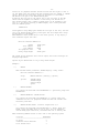
-30USING <expr>
using register bank
Sets the register bank used to <expr>, which must be in the range
of 0...3. The USING instruction only affects the values of the
special assembler symbols AR0, ... , AR7 representing the direct
addresses of registers R0, ... , R7 in the current register bank.
The value of <expr> must be known on pass 1!
The default value for the register bank is 0.
Example:
USING 1
END
end of program
This must be the last statement in the source file. After the END
statement only commentary and blank lines are allowed!
Example:
<symbol>
<symbol>
<symbol>
<symbol>
EQU
EQU
SET
SET
END
;end of program
<expr>
<reg>
<expr>
<reg>
define
define
define
define
numeric constant
invariant register
numeric variable
variable register
The EQU instruction defines a symbol for a numeric constant or a
register. If a numeric expression <expr> is assigned to the symbol,
it will be of the type NUMBER. If a register <reg> is assigned to
the symbol, it will be of the type REGISTER. <reg> may be one of the
special assembler symbols A, R0, R1, R2, R3, R3, R4, R5, R6, or R7.
A symbol once defined with EQU can never be changed!
The SET instruction is working quite similar to EQU. However, symbols
defined with SET can be redefined with subsequent SET instructions!
The values of <expr> and <reg> must be known on pass 1!
A symbol that has been SET, cannot be redefined with EQU!
A symbol that has been EQU'd cannot be reSET!
On pass 2, forward references to a SET symbol always evaluate
to the last value, the symbol has been SET to on pass 1.
Register symbols can be used as instruction operands within the
whole program instead of the corresponding registers.
Forward references to register symbols are not allowed!
Examples:
MAXMONTH EQU 12
OCTOBER EQU MAXMONTH-2
COUNTREG EQU R5
CHAPTER
CHAPTER
CHAPTER
<symbol>
<symbol>
<symbol>
<symbol>
<symbol>
CODE
DATA
IDATA
BIT
XDATA
SET 1
SET CHAPTER+1
SET A
<expr>
<expr>
<expr>
<expr>
<expr>
define
define
define
define
define
ROM address
direct RAM address
indirect RAM address
bit address
external RAM address
These instructions define symbolic addresses for the five 8051
memory segments (address spaces). For DATA, IDATA and BIT type
symbols, the value of <expr> must not exceed 0FFH!
The value of <expr> must be known on pass 1!
Once defined with one of the above instructions, the symbols cannot
be redefined.
Examples:
EPROM
STACK
V24BUF
REDLED
SAMPLER
CODE 08000H
DATA
7
IDATA 080H
BIT
P1.5
XDATA 0100H
-31CSEG
DSEG
ISEG
BSEG
XSEG
[AT
[AT
[AT
[AT
[AT
<expr>]
<expr>]
<expr>]
<expr>]
<expr>]
switch
switch
switch
switch
switch
to
to
to
to
to
CODE
DATA
IDATA
BIT
XDATA
segment
segment
segment
segment
segment
[at
[at
[at
[at
[at
address]
address]
address]
address]
address]
These instructions switch to one of the five 8051 address spaces.
If a segment base address is specified with "AT <expr>", a new
absolute segment is started, and the location counter is set to
<expr>. If "AT <expr>" is omitted, the location counter keeps the
previous value of the particular segment.
The value of <expr> must be known on pass 1!
At program start, the default segment is CODE and the base addresses
and location counters of all segments are set to zero.
Examples:
DSEG
;switch to previous DATA segment
CSEG AT 8000h ;start a new CODE segment at address 8000H
XSEG at 0
;start a new XDATA segment at address 0
-32-
III.7 Segment Type
-----------------Every assembly time expression is assigned a segment type, depending on
its operands and operators. The segment type indicates the address space,
the expression result might belong to, if it were used as an address.
There are six possible segment types:
CODE
DATA
IDATA
XDATA
BIT
NUMBER
(typeless)
Most expression results have the segment type NUMBER. That means they are
assumed to be typeless. However, in some cases it may be useful to assign
a particular segment type!
The following six rules apply when the segment type is evaluated:
1. Numerical constants are always typeless.
Consequently their segment type is NUMBER.
2. Symbols are assigned a segment type during definition. Symbols
that are defined with EQU or SET have no segment type.
Labels get the segment type of the currently active segment.
3. The result of a unary operation (+, -, NOT, HIGH, LOW) will have
the segment type of its operand.
4. The results of all binary operations (except "+", "-" and ".") will
have no segment type.
5. If only one operand in a binary "+" or "-" operation has a segment
type, then the result will have that segment type, too. In all other
cases, the result will have no segment type.
6. The result of the bit operation "." will always have the segment
type BIT.
Examples:
---------
The following symbols have been defined in a program:
OFFSET
START
DOIT
REDLED
VARIAB4
PORT
RELAY
1.)
2.)
3.)
4.)
5.)
The
The
The
The
The
expression
expression
expression
expression
expression
EQU
CODE
CODE
BIT
DATA
DATA
EQU
16
30H
0100H
P1.3
20H
0C8H
5
START+OFFSET+3
START+DOIT
DOIT-REDLED
2*VARIAB4
PORT.RELAY
will
will
will
will
will
have the segment type CODE.
be typeless.
be typeless.
be typeless.
have the segment type BIT.
The segment type is checked, when expressions appear as addresses. If the
expression result is not typeless and does not have the segment type of the
corresponding segment, the instruction is flagged with an error message.
The only exceptions are the segment types DATA and IDATA, which are assumed
to be compatible in the address range of 0 to 7FH. Since ASEM-51 does only
support absolute segments, those addresses are really always pointing to the
same physical location in the internal memory.
Example:
-------Line I Addr Code
1:
N
Source
30
DSEG AT 030H
;internal RAM
-332:
3:
4:
5:
30 N
0000 C2 30
01
COUNT: DS 1
;counter variable
CSEG
;ROM
START: CLR COUNT
^
@@@@@ segment type mismatch @@@@@
The CLR instruction is flagged with the error message "segment type mismatch"
in the assembler list file, because only a BIT type address is allowed here.
However, COUNT is a label with the segment type DATA!
-34-
III.8 Assembler Controls
-----------------------ASEM-51 implements a number of assembler controls that influence the
assembly process and list file generation. There are two groups of
controls: primary and general controls.
Primary controls can only be used at the beginning of the program and
remain in effect throughout the assembly. They may be preceded only
by control statements, blank and commentary lines. If the same primary
control is used multiple times with different parameters, the last one
counts.
General controls may be used everywhere in the program. They perform a
single action, or remain in effect until they are cancelled or changed by
a subsequent control statement.
A control statement starts always with a '$' character, followed by one or
more assembler controls.
Assembler controls may have a number or string type operand, which must
always be enclosed in parentheses.
Number type operands are arithmetic expressions that must be known on pass 1.
String type operands are character strings which are enclosed in parentheses
instead of quotes. In analogy to quoted strings, no control characters
(including tabs) are allowed within these strings! The string delimiter ')'
can be represented by two subsequent ')' characters.
If a control statement changes the listing mode, the control statement itself
is always listed in the previous listing mode!
The following table lists all the implemented controls and their abbreviations:
Control
Type Default
Abbreviation
Meaning
------------------------------------------------------------------------------$COND
G $COND
--list full IFxx .. ENDIF constructions
$NOCOND
G
--don't list lines in false branches
$CONDONLY
G
--list assembled lines only
------------------------------------------------------------------------------$DATE(string)
P
''
$DA
inserts date string into page header
------------------------------------------------------------------------------$DEBUG
P $NODEBUG
$DB
include debug information into object
$NODEBUG
P
$NODB
don't include debug information
------------------------------------------------------------------------------$EJECT
G
$EJ
start a new page in list file
------------------------------------------------------------------------------$ERROR(string) G
--force a user-defined error
$WARNING(string) G
--output a warning message to console
------------------------------------------------------------------------------$GEN
G $GEN
$GE
list macro calls and expansion lines
$NOGEN
G
$NOGE
list macro calls only
$GENONLY
G
$GO
list expansion lines only
------------------------------------------------------------------------------$INCLUDE(file) G
$IC
include a source file
------------------------------------------------------------------------------$LIST
G $LIST
$LI
list subsequent source lines
$NOLIST
G
$NOLI
don't list subsequent source lines
------------------------------------------------------------------------------$MACRO(n)
P $MACRO(50) $MR
reserve n % of free memory for macros
$NOMACRO
P
$NOMR
reserve all for the symbol table
------------------------------------------------------------------------------$MOD51
P $MOD51
$MO
enable predefined SFR symbols
$NOMOD51
P
$NOMO
disable predefined SFR symbols
------------------------------------------------------------------------------$NOBUILTIN
P list SFR
--don't list predefined symbols
------------------------------------------------------------------------------$NOTABS
P use tabs
--don't use tabs in list file
------------------------------------------------------------------------------$PAGING
P $PAGING
$PI
enable listing page formatting
$NOPAGING
P
$NOPI
disable listing page formatting
------------------------------------------------------------------------------$PAGELENGTH(n) P n=64
$PL
set lines per page for listing
------------------------------------------------------------------------------$PAGEWIDTH(n)
P n=132
$PW
set columns per line for listing
------------------------------------------------------------------------------$PHILIPS
P MCS-51
--switch on 83C75x family support
-35------------------------------------------------------------------------------$SAVE
G
$SA
save current $LIST/$GEN/$COND state
$RESTORE
G
$RS
restore old $LIST/$GEN/$COND state
------------------------------------------------------------------------------$SYMBOLS
P $SYMBOLS
$SB
create symbol table
$NOSYMBOLS
P
$NOSB
don't create symbol table
------------------------------------------------------------------------------$TITLE(string) G copyright $TT
inserts title string into page header
------------------------------------------------------------------------------$XREF
P $NOXREF
$XR
create cross reference
$NOXREF
P
$NOXR
don't create cross reference
The subsequent paragraphs contain detailed explanations of the implemented
controls.
-36-
III.8.1 Primary Controls
-----------------------$DATE (string)
Inserts a date string into the list
If $DATE() is specified, the actual
Date strings will be truncated to a
11 characters.
Default is: no date string.
The control has no effect, when the
been specified.
file page header.
date is inserted.
maximum length of
$NOPAGING control has
$DEBUG
Includes debug information into the OMF-51 module. When
generating Intel-HEX file output, $DEBUG has no effect.
$NODEBUG
Don't include debug information. (Default!)
$MACRO (n)
Save macro definitions and expand macro calls. (Default!)
Optionally reserve n % of free memory for macro definitions.
(0 <= n <= 100)
Default is n=50.
The control has been implemented for compatibility purposes
only. In ASEM-51 it has no effect except that it cancels
the $NOMACRO control.
$NOMACRO
Don't save macro definitions and don't expand macro calls.
Reserve all free memory for the symbol table.
The control has been implemented for compatibility purposes
only. In ASEM-51, it only suppresses the macro expansion.
$MOD51
Switches on the built-in 8051 special function register
and interrupt symbol definitions. (Default!)
$NOMOD51
Switches off the built-in 8051 special function register
and interrupt symbol definitions. The predefined symbols
??ASEM_51 and ??VERSION cannot be switched off!
$PAGING
Switches on the page formatting in the list file.
(Default!)
$NOPAGING
Switches off the page formatting in the list file.
$PAGELENGTH (n)
Sets the list file page length to n lines.
(12 <= n <= 65535)
Default is n=64.
The control has no effect, when the $NOPAGING control has
been specified.
$PAGEWIDTH (n)
Sets the list file page width to n columns.
(72 <= n <= 255)
Default is n=132.
$PHILIPS
Switches on the Philips 83C75x family support option.
This disables the LJMP, LCALL, and MOVX instructions as
well as the XDATA and XSEG pseudo instructions. Generic
jumps and calls will always assemble to absolute addressing.
$SYMBOLS
Generates the symbol table at the end of the list file.
(Default!)
When the $XREF control is active, $SYMBOLS has no effect!
$NOSYMBOLS
Suppresses the symbol table at the end of the list file.
When the $XREF control is active, $NOSYMBOLS has no effect!
$NOBUILTIN
Suppresses the predefined (built-in) symbols in the symbol
table or cross-reference listing for a better survey.
Only the user-defined symbols are listed.
$NOTABS
Expands all tab characters in the list file output to
blanks.
-37$XREF
Generates a cross-reference listing instead of a symbol
table. Note that this slightly slows down assembly, and
consumes about 67 % more memory space!
$NOXREF
Generates a symbol table instead of a cross-reference
listing. (Default!)
Examples:
$NOMOD51
$PAGELENGTH(60)
$PW(80)
$NOSYMBOLS
$NOTABS
$DATE(2. 8. 95)
$XREF
$ DEBUG NOPAGING
;switch off 8051 SFR symbol definitions
;set page length to 60 lines per page
;set page width to 80 characters per line
;no symbol table required
;printer doesn't support tab characters
;date of latest version
;generate a cross-reference listing
;include debugging information into OMF-51
;modules, and suppress page formatting
III.8.2 General Controls
-----------------------$COND
List full IFxx .. ELSEIFxx .. ELSE .. ENDIF constructions.
(Default!) The Control is overridden by $NOLIST.
$NOCOND
Don't list lines in false IFxx .. ELSEIFxx .. ELSE .. ENDIF
branches. The Control is overridden by $NOLIST.
$CONDONLY
List lines in true IFxx .. ELSEIFxx .. ELSE .. ENDIF
branches only, without the IFxx, ELSEIFxx, ELSE and ENDIF
statements itself. The Control is overridden by $NOLIST.
$EJECT
Starts a new page in the list file.
The control has no effect, when the $NOPAGING control has
been specified.
$ERROR (string)
Forces an assembly error with a user-defined error message.
This is intended to support configuration management and
can be applied sensefully with conditional assembly only.
$WARNING (string) Outputs a user-defined warning message to the console, and
increments the warning count. This is also intended to ease
configuration management.
$GEN
List macro calls and expanded macros. (Default!)
The listing fully shows the nesting of macro calls.
The Control is overridden by $NOLIST.
$NOGEN
List macro calls only. The expanded macros are not listed.
The Control is overridden by $NOLIST.
$GENONLY
List the expanded macro bodies only. Macro calls and EXITM
statements are not listed.
The Control is overridden by $NOLIST.
$INCLUDE (file)
Includes an external source file into the assembler program
just behind the $INCLUDE statement. If the include file has
not been specified with an absolute path, and it cannot be
found in the default directory, the path specified with the
/INCLUDES command line option (if present) is searched from
left to right, and if it cannot be found there either, the
path specified with the environment variable ASEM51INC (if
defined) is searched from left to right as well.
Include files may be nested to any depth.
$LIST
List source code lines. (Default!)
$NOLIST
Do not list source code lines, provided they do not contain
errors, until the next $LIST statement occurs.
$SAVE
Saves the current $LIST/$GEN/$COND state on a $SAVE-stack.
$SAVE statements can be nested to any depth.
-38$RESTORE
Restores a previously saved $LIST/$GEN/$COND state.
$TITLE (string)
Inserts a title string into the list file page header.
Titles may be truncated according to the specified (or
default) page width.
Default: ASEM-51 copyright information.
The control has no effect, when the $NOPAGING control has
been specified.
Examples:
$NOLIST
;switch off listing
$INCLUDE (8052.MCU)
;include 8052 SFR symbol definition file
$LIST
;switch on listing
$TITLE (Computer-Controlled Combustion Unit for Motorcycles)
$EJ
;new page with new title
$ERROR(invalid configuration: buffer size > external RAM size)
$WARNING(int. RAM doesn't meet minimum stack size requirements)
$SAVE GENONLY CONDONLY ;save old $LIST/$GEN/$COND status, and list
;only source lines that are really assembled
$RESTORE
;restore previous listing mode
III.9 Predefined Symbols
-----------------------For easy access to the 8051 special function register and interrupt
addresses, ASEM-51 has a number of predefined (built-in) DATA, BIT and
CODE symbols.
These predefined symbols can be switched off with the $NOMOD51 control.
For detailed information on symbols and addresses refer to Appendix C.
For identification of the assembler and its version number, the following
NUMBER type symbols are predefined:
??ASEM_51 = 8051H
??VERSION = 0130H
ASEM-51
version 1.3
These two symbols can not be switched off!
-39-
III.10 Conditional Assembly
--------------------------Conditional assembly allows to assemble or ignore selected parts of code.
This can be used to keep the code for various program variants in a single
source, to ease configuration control and maintenance. Conditional assembly
is also useful to write fancy macros.
The following fourteen meta instructions have been implemented:
IF
IFN
IFDEF
IFNDEF
IFB
IFNB
ENDIF
<expr>
<expr>
<symbol>
<symbol>
<literal>
<literal>
ELSEIF
ELSEIFN
ELSEIFDEF
ELSEIFNDEF
ELSEIFB
ELSEIFNB
ELSE
<expr>
<expr>
<symbol>
<symbol>
<literal>
<literal>
Meta instructions overlay the Intel MCS-51 assembly language, but are not
part of it! C programmers may compare them to C preprocessor commands.
In the subsequent text, IFxx is used as a collective name for the
IF/IFN/IFDEF/IFNDEF/IFB/IFNB instructions. In analogy ELSEIFxx is used as a
collective name for the ELSEIF/ELSEIFN/ELSEIFDEF/ELSEIFNDEF/ELSEIFB/ELSEIFNB
instructions (not including ELSE).
III.10.1 General IFxx Construction
---------------------------------Simple IFxx ... ENDIF constructions can be used to assemble a number of
enclosed statements only, if a particluar condition is met:
IFxx <condition>
<statement 1>
<statement 2>
.
.
<statement n>
ENDIF
;assembled if <condition> is TRUE
The statements 1 through n are assembled if <condition> is TRUE, otherwise
they are ignored.
If it should be possible to select two variants of code depending on a
particular condition, this can be done with an IFxx .. ELSE .. ENDIF
construction. If the <condition> in the IFxx statement is TRUE, then
statements 1 to n are assembled and the statements n+1 to n+m are ignored.
IFxx <condition>
<statement 1>
.
<statement n>
ELSE
<statement n+1>
.
<statement n+m>
ENDIF
;assembled if <condition> is TRUE
;assembled if <condition> is FALSE
Should <condition> be FALSE, it is exactly vice versa! That means the
statements 1 to n are ignored and the statements n+1 to n+m are assembled.
This works also, if the IFxx or ELSE branches contain no statements at all.
Whenever more than two cases have to be distinguished, a corresponding number
of ELSEIFxx branches can be inserted between the IFxx and the ELSE branch.
In such an IFxx .. ELSEIFxx .. ELSE .. ENDIF construction, only the statements
in the branch with the first TRUE condition are assembled. The statements in
all other branches are ignored.
If none of the conditions is TRUE, only the statements in the ELSE branch
(if any) are assembled.
IFxx <condition 1>
.
.
;assembled if <condition 1> is TRUE
-40ELSEIFxx <condition 2>
.
;assembled if <condition 1> is FALSE,
.
;and <condition 2> is TRUE
ELSEIFxx <condition 3>
.
;assembled if <condition 1> and
.
;<condition 2> are FALSE, and
.
;<condition 3> is TRUE
.
.
ELSEIFxx <condition n>
.
;assembled if <condition 1> thru
.
;<condition n-1> are FALSE and
.
;<condition n> is TRUE
ELSE
.
;assembled if <condition 1> thru
.
;<condition n> are FALSE
ENDIF
IFxx ... ELSEIFxx ... ELSE ... ENDIF constructions may be nested to any depth!
The listing mode of those constructions can be set with the $COND, $NOCOND and
$CONDONLY controls.
III.10.2 IFxx and ELSEIFxx Instructions
--------------------------------------The particular IFxx instructions are working as follows:
IF <expr>
The IF condition is TRUE, if the expression <expr> is not
equal to 0. The value of <expr> must be known on pass 1!
IFN <expr>
The IFN condition is TRUE, if the expression <expr> is
equal to 0. The value of <expr> must be known on pass 1!
IFDEF <symbol> The IFDEF condition is TRUE, if the <symbol> is defined in
the program. Forward references to <symbol> are not allowed!
IFNDEF <symbol> The IFNDEF condition is TRUE, if the <symbol> is not defined
in the program. Forward references to <symbol> are not allowed!
IFB <literal>
The IFB (if blank) condition is TRUE, if the <literal> is
empty. <literal> is a string, enclosed in angle brackets.
IFNB <literal> The IFNB (if not blank) condition is TRUE, if the <literal> is
not empty. <literal> is a string, enclosed in angle brackets.
Although the IFB
macros, they can
Usually they are
been left blank,
and IFNB statements are valid also outside of
be applied sensefully in macro bodies only.
used to decide, whether macro arguments have
or not.
The corresponding ELSEIFxx instructions are working respectively.
Example 1: IF .. ELSE .. ENDIF construction
---------TARGET EQU 0
;configuration: 1 for
;-------------- 0 for
IF TARGET
ORG 0
;program start address
ELSE
ORG 8000H
;program start address
ENDIF
application board
evaluation board
of application board
of evaluation board
Currently the program is configured for the evaluation board
version.
Example 2: IFNDEF .. ELSE .. ENDIF construction
---------;EVA_537 EQU 0
;symbol undefined: 80C537 application board
;symbol defined: 80C537 evaluation board
IFNDEF EVA_537
-41CLOCK
CSEG
ELSE
CLOCK
CSEG
ENDIF
EQU 16
AT 0
;clock frequency of application board
;program start address of application board
EQU 12
;clock frequency of evaluation board
AT 8000H ;program start address of evaluation board
Currently the program is configured for the application board
version.
Example 3: IFB .. ELSE .. ENDIF construction
---------DECIDE MACRO X, Y
IFB <X&Y>
NOP
NOP
ELSE
DB '&X,&Y'
ENDIF
ENDM
If the above macro is invoked as follows,
DECIDE Nonsense
the parameter X will be replaced by "Nonsense" and the
parameter Y by a zero length string. Thus the IFB literal
becomes <Nonsense>, and the macro will be expanded to:
DB 'Nonsense,'
If the macro will be invoked without arguments,
DECIDE
the parameters X and Y will be replaced by zero length
strings both, and the IFB literal becomes <>. Thus the
macro will be expanded to:
NOP
NOP
Macros are explained in detail in chapter
"III.11 Macro Processing".
Example 4: IFNDEF .. ELSEIF .. ELSEIF .. ELSE .. ENDIF construction
---------The symbol BAUDRATE serves to define the UART baudrate:
IFNDEF BAUDRATE
LJMP AUTOBAUD
;automatic baudrate detection
ELSEIF BAUDRATE EQ 9600
MOV TH1, #0FDH
;9600 baud
ELSEIF BAUDRATE EQ 1200
MOV TH1, #0E8H
;1200 baud
ELSE
$ERROR(baudrate not implemented)
ENDIF
If the symbol BAUDRATE is not defined at all, a jump to
the label AUTOBAUD is performed.
If the symbol BAUDRATE is defined with one of the legal
values 9600 or 1200, timer 1 is initialized accordingly.
If the symbol BAUDRATE is defined with another value, a
corresponding user-defined error message is generated.
-42-
III.11 Macro Processing
----------------------Macros allow to combine basic assembler instructions to "super commands".
For this, macros are defined as blocks of code, which can be used in a
program, wherever it is desired.
However, an advanced macro design with parameters, local symbols and macro
operators, combined with conditional assembly, goes far beyond this basic
functionality!
With only five keywords (MACRO, REPT, ENDM, EXITM, LOCAL) and some control
characters the ASEM-51 macro processor provides a variety of powerful tools.
These five meta instructions are not part of the Intel MCS-51 assembly
language, but overlay it, as already known from conditional assembly.
There are two sorts of macros: callable macros and repeat blocks.
III.11.1 Simple Callable Macros
------------------------------Macros must first be defined, before they can be called in a program.
A simple macro definition consists of the macro name, which can be defined
with the keyword MACRO, the macro body, and a final ENDM (end macro)
instruction.
<macro name> MACRO
<body line 1>
<body line 2>
.
.
<body line m>
ENDM
The macro name must be a valid, unique symbol. It cannot be redefined later.
Keywords cannot be used as macro names.
The macro body may comprise any number of lines. Body lines may be all kinds
of assembler instructions, pseudo instructions, controls, meta instructions,
macro calls and even further macro definitions.
The macro body and the whole macro definition is terminated with the ENDM
instruction.
Macros must be defined, before they can be called. Forward references to
macros are not allowed. Once defined, a macro can be called by its name in
the subsequent program as often as desired. Whenever a macro is called, the
macro body will be "inserted" into the program and then assembled as normal
source lines. This process is called macro expansion.
Example:
--------
MY_FIRST MACRO ;definition
MOV A,#42
ADD A,R5
ENDM
MY_FIRST
;call
After the call of the macro MY_FIRST, the body lines
MOV A,#42
ADD A,R5
are inserted into the program and assembled.
III.11.2 Macro Parameters
------------------------Callable macros may have parameters, to allow more flexible use.
The names of the formal parameters are specified in the macro definition
behind the keyword MACRO, separated by commas. All parameter names of a
macro must be different, valid symbols. Keywords cannot be used as
parameter names. Macros may have any number of parameters, as long as they
fit on one line. Parameter names are local symbols, which are known within
the macro only. Outside the macro they have no meaning!
<macro name> MACRO <parameter 1>, <parameter 2>, ... ,<parameter n>
<body line 1>
-43<body line 2>
.
.
<body line m>
ENDM
When called, actual arguments can be passed to the macro. The arguments
must be separated by commas. Valid macro arguments are
1. arbitrary sequences of printable characters, not containing blanks,
tabs, commas, or semicolons
2. quoted strings (in single or double quotes)
3. single printable characters, preceded by '!' as an escape character
4. character sequences, enclosed in literal brackets < ... >, which may
be arbitrary sequences of valid macro arguments (types 1. - 4.),
blanks, commas and semicolons
5. arbitrary sequences of valid macro arguments (types 1. - 4.)
6. expressions preceded by a '%' character
Note: The keywords MACRO, EQU, SET, CODE, DATA, IDATA, XDATA, BIT, and
the ':' character cannot be passed as the first macro argument,
because they always start a symbol definition!
Therefore they must be enclosed in literal brackets < ... >.
During macro expansion, these actual arguments replace the symbols of the
corresponding formal parameters, wherever they are recognized in the macro
body. The first argument replaces the symbol of the first parameter, the
second argument replaces the symbol of the second parameter, and so forth.
This is called substitution.
Without special assistance, the assembler will not recognize a parameter
symbol if it
- is part of another symbol
- is contained in a quoted string
- appears in commentary
Example 1:
----------
MY_SECOND MACRO CONSTANT, REGISTER
MOV A,#CONSTANT
ADD A,REGISTER
ENDM
MY_SECOND 42, R5
After calling the macro MY_SECOND, the body lines
MOV A,#42
ADD A,R5
are inserted into the program, and assembled.
The parameter names CONSTANT and REGISTER have been
replaced by the macro arguments "42" and "R5".
The number of arguments, passed to a macro, can be less (but not greater)
than the number of its formal parameters. If an argument is omitted, the
corresponding formal parameter is replaced by an empty string.
If other arguments than the last ones are to be omitted, they can be
represented by commas.
Example 2:
----------
The macro OPTIONAL has eight formal parameters:
OPTIONAL MACRO P1,P2,P3,P4,P5,P6,P7,P8
.
.
<macro body>
-44.
.
ENDM
If it is called as follows,
OPTIONAL 1,2,,,5,6
the formal parameters P1, P2, P5 and P6 are replaced by the
arguments 1, 2, 5 and 6 during substitution. The parameters
P3, P4, P7 and P8 are replaced by a zero length string.
For more flexible macro design, there must be a possibility to recognize
empty macro arguments, and to branch the macro expansion accordingly.
This can be performed with conditional assembly, using the IFB and IFNB
meta instructions. (See chapter "III.10.2 IFxx and ELSEIFxx Instructions".)
III.11.3 Repeat Macros
---------------------Repeat macros don't have a macro name, and therefore cannot be called
multiple times. They are always expanded immediately after their definition.
During expansion, their macro body is repeated n times (0 <= n <= 65535).
Repeat macros start with the keyword REPT, followed by an expression, which
must be known on pass 1. In analogy to callable macros, there is a macro
body, which must be terminated with an ENDM instruction:
REPT <expression>
<body line 1>
<body line 2>
.
.
<body line m>
ENDM
The expression value specifies how many times the macro body is to be
repeated. Since repeat macros start with the keyword REPT, they are
sometimes also called "REPT blocks".
Example:
--------
REPT 5
NOP
ENDM
This REPT block will expand to five NOP instructions
immediately after its definition:
NOP
NOP
NOP
NOP
NOP
III.11.4 Local Symbols
---------------------Local symbols are symbols, which are only known within a macro body, but not
outside the macro. Symbols that are defined for the whole program, will
subsequently be called "global symbols" for better understanding.
We are already familiar with a special case of local symbols: formal macro
parameters. They appear in the macro definition only. Since they are
substituted during macro expansion, we don't have further problems with them.
But what happens with symbols that are defined in a macro body?
Example 1:
----------
The following simple macro is intended to read a character
from the 8051 UART, and to return it in A:
RECEIVE MACRO
UARTIN: JNB RI,UARTIN
MOV A,SBUF
CLR RI
ENDM
-45This will work only once! If the macro RECEIVE is called
multiple times, the label UARTIN will be multiply defined.
This can be solved by simply declaring the symbol UARTIN local.
For this, the LOCAL statement has been introduced. After the keyword
LOCAL, a list of local symbols can be specified, separated by commas.
These symbols will only be valid inside the macro that contains the LOCAL
statement. LOCAL statements may only be placed directly after the MACRO
or REPT statement, preceding the first body line. They may contain any
number of local symbols. The macro body may be preceded by an arbitrary
number of LOCAL statements.
Local symbols must be valid symbols, unique within the macro, and different
from the formal parameters (if any). Keywords cannot be used as local symbol
names. If a local symbol has the same name as a global symbol, the local
scope takes precedance during substitution.
When a macro is expanded, its local symbols are always substituted: the
formal parameters are replaced by the macro arguments, and the local symbols
that have been declared in a LOCAL statement are replaced by unique, global
symbol names, which the assembler generates during every expansion. These
have always the format ??xxxx, where xxxx is a unique symbol number.
Example 2:
----------
After a redesign of our previous macro RECEIVE using
local symbols, it is looking as follows:
RECEIVE MACRO
LOCAL UARTIN
UARTIN: JNB RI,UARTIN
MOV A,SBUF
CLR RI
ENDM
Enhanced as shown above, the macro will work correctly,
as often as desired. When RECEIVE is called for the first
time, the local symbol UARTIN will be replaced by ??0000,
??0000: JNB RI,??0000
MOV A,SBUF
CLR RI
when it is called for the second time, UARTIN will be
replaced by ??0001, and so on:
??0001: JNB RI,??0001
MOV A,SBUF
CLR RI
However, it is recommended not to define global symbols in the format ??xxxx,
to avoid name conflicts with substituted local symbols from expanded macros.
III.11.5 Macro Operators
-----------------------There are some special control characters, which are very useful for macro
definition, call and expansion:
;;
Macro commentary:
Normally, comments in body lines are also contained in the expanded
lines. If a commentary begins with ';;' however, it is not stored
during macro definition. Therefore, it doesn't consume memory space,
and appears in the list file in the macro definition only, but not
in the expanded lines.
!
Literal operator:
If the escape character '!' precedes another printable character in
a macro argument, the assembler is forced to treat that character
literally. This means it will be passed to the macro, even if it is
a control character, while the literal operator itself is removed.
< >
Literal brackets:
If a macro argument is intended to contain separation or control
characters, it must be enclosed in literal brackets < ... > to pass
it to the macro as one argument string, while the outermost pair of
-46brackets is removed. Literal brackets can be nested to any depth.
%
Evaluation:
If a macro argument is preceded by the evaluation operator '%', it
is interpreted as an expression, which will be evaluated before it
is passed to the macro. The actual argument string will not be the
expression itself, but a decimal ASCII representation of its value.
The expression must be known on pass 1.
&
Substitution:
The '&' character separates parameter names (local symbols) from
surrounding text. Outside quoted strings and commentary it serves
only as a general separation character. This applies always when
a local symbol directly precedes or follows another alphanumeric
string. Inside quoted strings and commentary, a local symbol must
be preceded by '&' if it is to be substituted there.
During every macro expansion, the assembler removes exactly one '&'
from every sequence of '&' characters. This allows for example, to
define a nested macro inside a macro body, which also uses the
substitution operator '&': one writes simply '&&'!
Example 1:
----------
The commentary should only be visible in the definition
of the macro LICENSE:
LICENSE MACRO
DB 'Copyright' ;;legal stuff
ENDM
When called, the expanded macro body is looking
like this in the list file:
DB 'Copyright'
Example 2:
----------
SPECIAL !;
passes a semicolon to the macro SPECIAL as a literal
argument. This could also be done with
SPECIAL <;>
Example 3:
----------
The macro CONST defines a 16-bit constant in ROM:
CONST MACRO NUMB
DW NUMB
ENDM
If it is called as shown below,
CONST 0815H+4711-42
the parameter NUMB would be substituted as follows:
DW 0815H+4711-42
If the same macro argument is preceded by a '%' however,
CONST %0815H+4711-42
the substitution will result in:
DW 6738
Example 4:
----------
During substitution, both arguments of the macro CONCAT
should form a seamless symbol name:
CONCAT MACRO NAM, NUM
MOV R3,#0
NAM&NUM: DJNZ R3,NAM&NUM
ENDM
When CONCAT is called as follows,
-47CONCAT LABEL, 08
the parameters NAM and NUM are substituted during macro
expansion as shown below:
MOV R3,#0
LABEL08: DJNZ R3,LABEL08
III.11.6 Premature End of a Macro Expansion
------------------------------------------Sometimes it is useful, if a macro expansion can be terminated, before
the end of the macro body is reached. This can be forced with the EXITM
(exit macro) instruction. However, this makes sense in conjunction with
conditional assembly only.
Example:
--------
FLEXIBLE MACRO QUANTITY
DB 'Text'
IF QUANTITY LE 255
EXITM
ENDIF
DW QUANTITY
ENDM
The macro FLEXIBLE always has to insert the string 'Text'
into the CODE space. After that, it should insert a 16-bit
constant only, if the numerical value of the parameter
QUANTITY is greater than 255.
Otherwise the macro expansion should be terminated with
EXITM before. If the macro is called as follows,
FLEXIBLE 42
it will be expanded to
DB 'Text'
in list mode $GENONLY/$CONDONLY.
However, if it is called like this,
FLEXIBLE 4711
it will be expanded to:
DB 'Text'
DW 4711
When a macro expansion is terminated with EXITM, all IFxx constructions that
have been opened within the macro body so far, are closed.
Of course macro bodies may also contain control statements. If an include
file is inserted into a macro body with a $INCLUDE control, and this include
file, or a nested include file, contains an EXITM instruction, all include
file levels up to the next macro level are closed at this point, and the
expansion of that macro is terminated immediately.
III.11.7 Nested and Recursive Macro Calls
----------------------------------------Macro bodies may also contain macro calls, and so may the bodies of those
called macros, and so forth.
If a macro call is seen throughout the expansion of a macro, the assembler
starts immediately with the expansion of the called macro. For this, its
its expanded body lines are simply inserted into the expanded macro body of
the calling macro, until the called macro is completely expanded. Then the
expansion of the calling macro is continued with the body line following
the nested macro call.
Example 1:
----------
INSIDE MACRO
SUBB A,R3
ENDM
OUTSIDE MACRO
-48MOV A,#42
INSIDE
MOV R7,A
ENDM
In the body of the macro OUTSIDE, the macro ISIDE is called.
If OUTSIDE is called (and the list mode is set to $GENONLY),
one gets something like the following expansion:
Line I Addr Code
15+ 1 0000 74 2A
17+ 2 0002 9B
18+ 1 0003 FF
Source
MOV A,#42
SUBB A,R3
MOV R7,A
Since macro calls can be nested to any depth (while there is free memory),
the macro expansion level is shown in the I-column of the list file.
Since macro and include file levels can be nested in arbitrary sequence and
depth, the nesting level is counted through all macro and include file
levels regardless. For better distinction, the character following the
global line number is ':' for include file levels, and '+' for macro levels.
If macros are calling themselves, one speaks of recursive macro calls.
In this case, there must be some stop criterion, to prevent the macro of
calling itself over and over until the assembler is running out of memory!
Here again, conditional assembly is the solution:
Example 2:
----------
The macro COUNTDOWN is to define 16-bit constants from
1 thru n in descending order in ROM. n can be passed to
the macro as a parameter:
COUNTDOWN MACRO DEPTH
IF DEPTH GT 0
DW DEPTH
COUNTDOWN %DEPTH-1
ENDIF
ENDM
If COUNTDOWN is called like this,
COUNTDOWN 7
something like the following macro expansion results
(in list mode $GENONLY/$CONDONLY):
Line I Addr Code
16+
19+
22+
25+
28+
31+
34+
1
2
3
4
5
6
7
0000
0002
0004
0006
0008
000A
000C
00
00
00
00
00
00
00
07
06
05
04
03
02
01
Source
DW
DW
DW
DW
DW
DW
DW
7
6
5
4
3
2
1
After the Dark Ages, when the dust was settling and the sun broke through
the gloom, computer science discovered the method of recursive programming.
There was no doubt that this was the SOLUTION!
And the computer scientists started to explain this to the students.
But it seemed that the students didn't get it. They always complained
that recursive calculation of n! is a silly example indeed.
All the scientists felt stronly that there was still something missing.
After 10 more years of hard research work, they also found the PROBLEM:
Example 3:
----------
The Towers of Hanoi
There are three vertical sticks on the table. On stick 1
there are n discs with different diameters and a hole in
the middle, the smallest disc on top, the biggest on the
bottom.
Stick 1
Stick 2
Stick 3
-49|
|
|
Disc 1
===|===
|
|
Disc 2
=====|=====
|
|
Disc n =======|=======
|
|
__________|________________|________________|__________
///////////////////////////////////////////////////////
The PROBLEM is to transfer the tower of discs from stick 1
to stick 2 with a minimum of moves. But only the topmost
disc on a tower may be moved at one time, and no disc may
be layed on a smaller disc. Stick 3 may be used for scratch
purposes. This is a SOLUTION with ASEM-51 macros:
;The Towers of Hanoi
$GENONLY CONDONLY
DISCS EQU 3
;number of discs
HANOI MACRO n, SOURCE, DESTINATION, SCRATCH
IF n > 0
HANOI %(n-1), SOURCE, SCRATCH, DESTINATION
; move topmost disc from stick &SOURCE to stick &DESTINATION
HANOI %(n-1), SCRATCH, DESTINATION, SOURCE
ENDIF
ENDM
HANOI DISCS, 1, 2, 3
END
The recursive macro HANOI generates an instruction manual
for the PROBLEM, where the instructions appear as comment
lines in the list file. The symbol DISCS must be set to
the desired number of discs. If HANOI is called like this,
HANOI 3, 1, 2, 3
the following "instruction manual" is generated:
27+
35+
44+
53+
64+
72+
81+
3
2
3
1
3
2
3
;
;
;
;
;
;
;
move
move
move
move
move
move
move
topmost
topmost
topmost
topmost
topmost
topmost
topmost
disc
disc
disc
disc
disc
disc
disc
from
from
from
from
from
from
from
stick
stick
stick
stick
stick
stick
stick
1
1
2
1
3
3
1
to
to
to
to
to
to
to
stick
stick
stick
stick
stick
stick
stick
2
3
3
2
1
2
2
The GENONLY and CONDONLY controls ensure that the table
doesn't contain all the macro calls and IF constructions.
Exercise 1:
Exercise 2:
Modify the macro HANOI so that it is generating a move
table in ROM, which could directly be used as an input
for an 8051-controlled robot-arm that really plays the
game with 3 real sticks and n real discs.
n
Prove that the minimum number of moves is 2 - 1. ;-)
III.11.8 Nested Macro Definitions
--------------------------------A macro body may also contain further macro definitions. However, these
nested macro definitions aren't valid until the enclosing macro has been
expanded! That means, the enclosing macro must have been called, before
the nested macros can be called.
Example 1:
----------
A macro, which can be used to define macros with arbitrary
names, may look as follows:
DEFINE MACRO MACNAME
MACNAME MACRO
-50DB 'I am the macro &MACNAME.'
ENDM
ENDM
In order not to overload the example with "knowhow",
the nested macro only introduces itself kindly with
a suitable character string in ROM. The call
:-)
DEFINE Obiwan
would define the macro
Obiwan MACRO
DB 'I am the macro Obiwan.'
ENDM
and the call
DEFINE Skywalker
would define the following macro:
Skywalker MACRO
DB 'I am the macro Skywalker.'
ENDM
Example 2:
----------
A macro is to insert a variable number of NOPs into the
program. For this, a macro with a nested REPT block seems
to be best-suited:
REPEAT MACRO NOPS
REPT NOPS
NOP
ENDM
ENDM
The macro call
REPEAT 4
results in something like that:
Line I Addr Code
9+
10+
11+
12+
13+
14+
15+
1
1
1
2
2
2
2
N
0000
0001
0002
0003
00
00
00
00
Source
0004
REPT 4
NOP
ENDM
NOP
NOP
NOP
NOP
III.11.9 Representation in the List File
---------------------------------------Sometimes macro expansions tend to produce much more listing lines than
resulting code. To list or not to list - that is the question!
The requirements to either get a better overall view or more detailed
information may vary in different development phases or program sections.
To always get the best results, a number of general controls has been
introduced, which influence the representation of macro expansions and IFxx
constructions in the list file (see chapter "III.8 Assembler Controls"):
Control Type Default Abbreviation
Meaning
-----------------------------------------------------------------------------$GEN
G
$GEN
$GE
list macro calls and expansion lines
$NOGEN
G
$NOGE
list macro calls only
$GENONLY
G
$GO
list expansion lines only
-----------------------------------------------------------------------------$COND
G
$COND
--list full IFxx .. ENDIF constructions
$NOCOND
G
--don't list lines in false branches
$CONDONLY G
--list assembled lines only
-51-----------------------------------------------------------------------------$SAVE
G
$SA
save current $LIST/$GEN/$COND state
$RESTORE
G
$RS
restore old $LIST/$GEN/$COND state
-52-
IV. Compatibility with the Intel Assembler
==========================================
With their cross assembler ASM51, Intel has defined and implemented a
suitable assembly language for the MCS-51 family, which has always been
the only real standard in the 8051 world.
Unfortunately, Intel has announced the "end of life" of ASM51 (final
version 2.3) and all the other Intel MCS-51 development tools to the
end of 1993.
The ASEM-51 assembly language is a subset of the Intel standard that
guarantees maximum compatibility with existing 8051 assembler sources.
It implements all 8051 instruction mnemonics as well as a rich and useful
subset of the Intel pseudo instructions and assembler controls.
IV.1 Restrictions
----------------Since ASEM-51 generates an Intel-HEX file (or absolute OMF-51) output
instead of relocatable object modules, the whole source code of an 8051
application program has to reside in one single file. Consequently all
pseudo instructions that deal with relocatable segments or external or
public symbols, have not been implemented:
PUBLIC
EXTRN
SEGMENT
RSEG
Intel-style macros are not supported! (Thus the '%' character can be used in
comments.)
Up to now only the following assembler controls and their abbreviations have
been implemented:
| primary controls
abbrev. | general controls
abbrev.
---------+-----------------------------------+----------------------------| $DATE (<string>)
$DA
| $EJECT
$EJ
| $DEBUG
$DB
| $GEN
$GE
| $NODEBUG
$NODB | $NOGEN
$NOGE
| $MACRO (<percent>)
$MR
| $GENONLY
$GO
| $NOMACRO
$NOMR | $INCLUDE (<file>)
$IC
Intel- | $MOD51
$MO
| $LIST
$LI
| $NOMOD51
$NOMO | $NOLIST
$NOLI
controls | $PAGING
$PI
| $SAVE
$SA
| $NOPAGING
$NOPI | $RESTORE
$RS
| $SYMBOLS
$SB
| $TITLE (<string>)
$TT
| $NOSYMBOLS
$NOSB |
| $PAGELENGTH (<lines>)
$PL
|
| $PAGEWIDTH (<columns>)
$PW
|
---------+-----------------------------------+----------------------------| $NOBUILTIN
----- | $COND
----ASEM-51 | $NOTABS
----- | $NOCOND
----controls | $PHILIPS
----- | $CONDONLY
----|
| $ERROR (<string>)
----|
| $WARNING (<string>) -----
IV.2 Extensions
--------------Assembler controls need not start in column 1, but may be preceded by any
number of blanks and tabs. Primary controls may also be preceded by comment
lines and $INCLUDE statements, provided the corresponding include files are
only containing other control statements and commentary.
The source file may contain blank and comment lines behind the END statement.
Character strings may also be enclosed in double quotes.
The DATA symbol for the special function register PCON is predefined.
The bit operator '.' is legal in all expressions, not only in those that
have to match the segment type BIT.
ASEM-51 introduces a set of meta instructions, which overlay the Intel MCS-51
assembly language, but are not part of it!
The meta instructions IFxx, ELSEIFxx, ELSE, and ENDIF allow conditional
-53assembly, while the meta instructions MACRO, REPT, ENDM, EXITM, and LOCAL
(and some control characters) form a powerful macro processing language.
For detailed information on meta instructions see chapters
"III.10 Conditional Assembly" and "III.11 Macro Processing".
IV.3 Further Differences
-----------------------To make semantics unique, especially the precedence of unary operators in
expressions is slightly different. Furthermore, expressions with a bit
operation "." evaluate to a BIT type result, not to NUMBER. The segment
type of symbols that are defined with EQU or SET evaluates always to NUMBER.
Otherwise it might be difficult in some cases, to force the definition of
typeless symbols. This is described in detail in chapters "III.4 Expressions"
and "III.7 Segment Type".
Except in DB instructions, the zero length string constant '' is illegal.
The $NOMOD51 control disables also the predefined CODE addresses.
The special assembler symbols AR0...AR7 are predefined for bank 0 before
the first USING statement occurs.
-54-
V. List File Format
===================
The ASEM-51 list file format has been designed to give the user as much
information about the generated code as possible.
Besides the source code listed, there are five basic layout structures
in the listing:
-
the
the
the
the
the
page header
file header
line headings
error diagnosis
symbol table or cross-reference listing
Normally, every page of the listing starts with a page header as shown below:
ASEM-51 V1.3
Copyright (c) 2001 by W.W. Heinz
PAGE 1
It identifies the assembler, contains the copyright information and shows the
actual page number at the right margin. After the page header, source lines
are output in the list file format. When the maximum number of lines per page
is reached, another page header is output after a form feed character.
If your printer doesn't support form feeds, the page header can be
suppressed with the $NOPAGING control. The number of lines per page can be
adjusted to the paper format with the $PAGELENGTH control. The width of the
page header (and all other lines) can be set with the $PAGEWIDTH control.
The file header appears only on the first page. It identifies the assembler,
lists all input and output files and marks the columns for the line headings.
A typical file header is looking as shown below:
MCS-51 Family Macro Assembler A S E M - 5 1 V 1.3
=====================================================
Source File:
Object File:
List File:
Line I Addr Code
demo.a51
demo.hex
demo.lst
Source
Directly after the file header starts the listing of the source code lines.
Every source code line is preceded by a line heading. The line heading
consists of four columns: line number, include file or macro level, line
address, and generated code.
By default the line headings contain tab characters to save disk space.
If your printer or file browser doesn't support tabs, they can be expanded
to blanks with the $NOTABS control.
The column "Line" contains the global line number. It is not necessarily
the local line number within the particular source file, but a global line
number that is counted over the main source, all include files, and all
macro expansion lines.
Since include files and macros can be nested arbitrarily, the global line
number is terminated by a ':' character for the main source and all include
file levels, and with a '+' character for macro expansion levels.
The column "I" flags the level of include file or macro nesting. In the main
source, this column is empty. The first include file gets level 1. If this
include file includes another include file, this one gets level 2, and so on.
This is also valid for nested macro calls. If a macro is called in the main
source, its expansion lines get level 1. If this macro calls another one, it
gets level 2, and so forth.
Include file and macro levels can be nested in any sequence and to any depth!
-55The column "Addr" shows the start address of the listed line in the currently
active segment (8051 address space). All addresses are represented as hex
numbers. The addresses in the CODE and XDATA segments are four-digit numbers.
Addresses in all other segments are two-digit numbers. For lines that cannot
be assigned to a particular segment, the "Addr" field is left blank.
The "Code" column may contain up to four bytes of generated code, which is
sufficient for all 8051 instructions. The code is listed in hex byte
quantities starting from the left margin of the "Code" column.
However, the code generated for DB and DW instructions may be longer than
four bytes. In these cases, the source code line is followed by additional
line headings until the whole code of the line is listed.
The "Code" column does not always contain code that consumes space in the
8051 CODE segment. In contrast to many other assemblers, ASEM-51 lists the
evaluation results of all expressions that may appear in pseudo instructions
or assembler controls. These values are listed in hex representation at the
right margin of the "Code" column. The segment type of those expressions is
flagged with one single character at the left margin of the "Code" column:
C
D
I
X
B
N
R
CODE
DATA
IDATA
XDATA
BIT
typeless number
register
The "Source" column finally contains the original source code line.
A typical source code listing is looking as follows:
Line I Addr Code
1:
2:
3:
4:
5:
6:
7:
8:
9:
10:
11:
12:
13:
14:
15:
16:
17:
18:
19:
20:
21:
22:
23:
24:
25:
26:
Source
N
004F
N
B
90
93
;A sample List File Demo Program
;------------------------------$NOMOD51
;no 8051 SFR
$PAGEWIDTH (79)
;79 columns per line
$NOTABS
;expand tabs
P1
DATA 090H ;port 1 address
INPUT BIT P1.3 ;pulse input
N
8000
8000 80 20
ORG 08000H
SJMP START
;set location counter
;jump to start address
8002
8004
8008
800A
800E
8012
8016
801A
801E
801F
01
00
00
63
65
67
28
31
00
N
07
02
09
6F
65
68
63
39
DB 1,7
DW 2,12,9
;define bytes
;define words
8022
8025
8028
802B
802D
75
30
20
05
80
30 00
93 FD
93 FD
30
F6
N
30 N
00 0C
66
72
74
29
39
66
69
20
20
39
0003
DB 'coffeeright (c) 1999',0
DS 3
;string
;define space
START: MOV COUNT,#0
;reset counter
LLEVEL: JNB INPUT,LLEVEL ;wait for high
HLEVEL: JB INPUT,HLEVEL ;wait for low
INC COUNT
;count pulse
JMP LLEVEL
;next pulse
30
01
DSEG AT 030H
COUNT: DS 1
;internal RAM
;counter variable
END
If an error is detected in a source line, its position is flagged with a ^
character as good as possible, and a comprehensive error message is inserted.
This is looking as shown below:
-5617:
18:
19:
8022 75 30 00
8025 30 93 FD
8028 20 93 00
20:
21:
802B 05 30
802D 80 F6
START: MOV COUNT,#0
;reset counter
LLEVEL: JNB INPUT,LLEVEL ;wait for high
HLEVEL: JB INPUT,HLEUEL ;wait for low
^
@@@@@ symbol not defined @@@@@
INC COUNT
JMP LLEVEL
;count pulse
;next pulse
The error diagnosis at the end of program lists the register banks used,
and the total number of errors detected throughout the assembly:
register banks used: 0, 1, 3
187 errors detected
A register bank counts as "used", if the program had switched to that
bank with a USING instruction, or one of the special assembler symbols
AR0 ... AR7 has been used, while the bank was active. The message
register banks used: --means, that no bank has been used explicitly, and that the program
code may, but need not, be register bank independent.
After the source code listing and error diagnosis, the symbol table or
cross-reference listing starts. By default, a symbol table is generated.
The symbol table lists all the symbols of a program in alphabetical order
with their symbol name, segment type, hex value and first definition line.
Predefined symbols are listed without a definition line number.
The symbol table listing can be suppressed with the $NOSYMBOLS control.
A typical symbol table listing is looking as shown below:
L I S T O F S Y M B O L S
=============================
SYMBOL
TYPE
VALUE
LINE
-----------------------------------------------------------AKKUM
REGISTER
A
38
COUNT
DATA
30
47
HLEVEL
CODE
802E
35
INPUT
BIT
93
12
LLEVEL
CODE
802B
34
MY_PROGRAM
MODULE
14
P1
DATA
90
QUANT
NUMBER
0013
22
RECEIVE
MACRO
5
SP
DATA
81
STACK
IDATA
80
17
START
CODE
8022
31
VOLTDC
XDATA
D785
50
If the $XREF control is specified, a cross-reference listing is generated
instead of a symbol table. The corresponding cross-reference listing for
the symbol table above is looking as follows:
C R O S S - R E F E R E N C E - L I S T I N G
=============================================
SYMBOL
TYPE
VALUE
DEFINED REFERENCED
------------------------------------------------------------------------------AKKUM
REGISTER
A
38
42
43
COUNT
DATA
30
47
32
40
-57HLEVEL
INPUT
LLEVEL
MY_PROGRAM
P1
QUANT
RECEIVE
SP
STACK
START
TRASH
VOLTDC
CODE
BIT
CODE
MODULE
DATA
NUMBER
NUMBER
MACRO
DATA
IDATA
CODE
undef.
XDATA
802E
93
802B
90
0007
0013
81
80
8022
---D785
35
12
34
14
22
37
5
17
31
50
43
35
34
34
44
35
41
12
44
31
31
24
42
33
It lists all the symbols of the program in alphabetical order, with their
symbol name, all definitions including definition lines, segment types, and
numerical values. Furthermore, all symbol references are listed as well.
The SYMBOL column contains the symbol name, while the columns TYPE, VALUE,
and DEFINED may contain the segment types, numerical values, and definition
lines of one, more, or no symbol defintions.
Register symbols have the symbol type "REGISTER", module names have the symbol
type "MODULE", macro names have the symbol type "MACRO", and symbols that have
been referenced but not defined, are flagged with "undef." in the TYPE column.
Starting from column REFERENCED up to the right margin, there is a number of
columns (depending on the page width), containing all line numbers of symbol
references (if any).
The cross-reference listing does not distinguish, whether multiple definitions
of, or references to a particular symbol are legal or not. For this, refer to
the error messages in the source listing.
-58-
VI. Support of 8051 Derivatives
===============================
Today a large number of 8051 derivatives is available that grows almost
monthly! They all use the same instruction set of the MCS-51 processor core,
but are different in peripheral components, to cover a wide range of
applications. The difference for the assembly language programmer is mainly
the varying set of special function registers and interrupt addresses.
It is always good practice to use the same SFR names in a microcontroller
application program that the manufacturer of the derivative used has defined.
For this the processor definition files *.MCU are provided. They all are
include files with the special function register definitions of a particular
8051 derivative. However, the predefined symbols of ASEM-51 must be switched
off prior to including the SFR definitions of another derivative as shown
below:
$NOMOD51
$INCLUDE (80C515.MCU)
This would switch off the predefined symbols of the 8051 and include the
register definitions of the 80C515 or 80C535 respectively.
Hence it is easy for the user to adapt ASEM-51 to a brandnew 8051 derivative!
All what he has to do is to write a corresponding include file with the SFR
definitions derived from the manufacturer's data sheet.
The name of every processor definition file is corresponding to the ROM
version of a particular derivative. Of course it also applies to the EPROM,
EEPROM, flash, and ROM-less versions (if any) of that derivative.
By the way, the file 8051.MCU provided contains exactly the predefined
symbols of ASEM-51, because its internal symbol table has been generated
from it!
To switch ASEM-51 to the reduced instruction set of the Philips 83C75x
family of microcontrollers, the $PHILIPS control can be used.
Currently the following processor definition files are provided with ASEM-51:
Name
Manufacturer
Versions
--------------------------------------------------------------------8051.MCU
Intel
8051, 8031, 8751BH
(and others)
8051AH, 8031AH, 8751H, 8051AHP, 8751H-8
80C51BH, 80C31BH, 87C51, 80C51BHP
Atmel
89C51, 89LV51, 87LV51, 80F51, 87F51
8052.MCU
Intel
8052AH, 8032AH, 8752BH
SIEMENS
80513, 8352-5
80C52.MCU
Intel
80C52, 80C32, 87C52,
80C54, 87C54, 80C58, 87C58
83C51FX.MCU
Intel
83C51FA, 80C51FA, 87C51FA
83C51FB, 87C51FB, 83C51FC, 87C51FC
83C51R.MCU
Intel
83C51RA, 80C51RA, 87C51RA,
83C51RB, 87C51RB, 83C51RC, 87C51RC
83C51KB.MCU
Intel
83C51KB
83C51GB.MCU
Intel
83C51GB, 80C51GB, 87C51GB
83C151.MCU
Intel
83C151SB, 87C151SB, 80C151SB
83C151SA, 87C151SA
83C152.MCU
Intel
80C152JA, 83C152JA, 80C152JB
80C152JC, 83C152JC, 80C152JD
83C452.MCU
Intel
83C452, 80C452
8044.MCU
Intel
8044AH, 8344AH, 8744AH
83931HA.MCU
Intel
83931HA, 80931HA
83931AA.MCU
Intel
83931AA, 80931AA
80512.MCU
SIEMENS
80512, 80532
80515.MCU
SIEMENS
80515, 80535, 80515K, 83515-4
80C515.MCU
SIEMENS
80C515, 80C535, 83C515H
83C515A.MCU
SIEMENS
83C515A-5, 80C515A
80C517.MCU
SIEMENS
80C517, 80C537
C501.MCU
SIEMENS
C501-1R, C501-L
C502.MCU
SIEMENS
C502-2R, C502-L
C503.MCU
SIEMENS
C503-1R, C503-L
C504.MCU
SIEMENS
C504-2R, C504-L
C509.MCU
SIEMENS
C509-L
C511.MCU
SIEMENS
C511, C511A
C513.MCU
SIEMENS
C513, C513A, C513A-H
-59C513AO.MCU
C515.MCU
C515A.MCU
C515C.MCU
C517A.MCU
C540U.MCU
C541U.MCU
83C451.MCU
83C528.MCU
SIEMENS
SIEMENS
SIEMENS
SIEMENS
SIEMENS
SIEMENS
SIEMENS
Philips
Philips
83C550.MCU
83C552.MCU
83C562.MCU
83C652.MCU
Philips
Philips
Philips
Philips
83C750.MCU
83C751.MCU
83C752.MCU
83C754.MCU
83C851.MCU
83C852.MCU
87LPC762.MCU
87LPC768.MCU
80C521.MCU
80C324.MCU
83C154.MCU
83C154S.MCU
80C310.MCU
80C320.MCU
80C390.MCU
87C520.MCU
87C530.MCU
87C550.MCU
89C420.MCU
DS5000.MCU
DS5001.MCU
MAX7651.MCU
COM20051.MCU
89C52.MCU
Philips
Philips
Philips
Philips
Philips
Philips
Philips
Philips
AMD
AMD
OKI
OKI
DALLAS
DALLAS
DALLAS
DALLAS
DALLAS
DALLAS
DALLAS
DALLAS
DALLAS
Maxim
SMC
Atmel
87F51RC.MCU
89C1051.MCU
89C2051.MCU
89S8252.MCU
89S51.MCU
89S52.MCU
89S53.MCU
89S4D12.MCU
73M2910.MCU
AN2131.MCU
Atmel
Atmel
Atmel
Atmel
Atmel
Atmel
Atmel
Atmel
TDK
Cypress
C513AO
C515-L, C515-1R
C515A-L, C515A-4R
C515C-8R
C517A-L, C517A-4R, 83C517A-5, 80C517A
C540U
C541U
83C451, 80C451, 87C451
83C528, 80C528, 87C528, 83C524, 87C524
83CE528, 80CE528, 89CE528
83C550, 80C550, 87C550
83C552, 80C552, 87C552
83C562, 80C562
83C652, 80C652, 87C652
83C654, 87C654, 83CE654, 80CE654
83C750, 87C750
83C751, 87C751
83C752, 87C752
83C754, 87C754
83C851, 80C851
83C852
87LPC762
87LPC768
80C521, 80C541, 87C521, 87C541, 80C321
80C324
83C154, 80C154, 85C154VS
83C154S, 80C154S, 85C154HVS
80C310
80C320, 87C320, 80C323, 87C323
80C390
87C520, 83C520
87C530, 83C530
87C550
89C420
5000FP, 5000, 5000T, 2250, 2250T
5001FP, 5002FP, 5002FPM, 2251T, 2252T
MAX7651, MAX7652
COM20051
89C52, 89C55, 89LV52, 89LV55, 87LV52,
80F52, 87F52
87F51RC, 87F55, 87LV55
89C1051
89C2051, 89C4051, 89C1051U
89S8252, 89LS8252
89S51
89S52, 89LS52
89S53, 89LS53
89S4D12
73M2910, 73M2910A
AN2121, AN2122, AN2125, AN2126,
AN2131, AN2135, AN2136
All SIEMENS derivatives are now manufactured and sold by Infineon!
-60-
Appendix A
==========
ASEM-51 Error Messages
---------------------A.1 Assembly Errors:
-------------------Assembly errors apply to the consistency of the assembly language
program in syntax and semantics. If one of these errors is detected,
it is flagged in the list file, and program execution continues.
When assembly is finished, ASEM terminates with exit code 1:
Error Message
Meaning
----------------------------------------------------------------------------address below segment base
Attempt to set the location counter
of the current segment below the
segment base address.
address out of range
The address of a jump or call
instruction cannot be reached with
the selected addressing mode.
already a macro parameter
In a macro definition, a local symbol
is equal to a previously defined
parameter name.
argument exceeds end of line
A macro argument contains more
opening than closing angle brackets.
attempt to divide by zero
During evaluation of an assembly time
expression, the assembler has to
divide by zero.
binary operator expected
In this position of an expression,
only binary operators are allowed.
comma expected
There should be a ',' character in
the marked position.
commands after END statement
The END statement is followed by
further assembler statements.
constant out of range
A numerical constant is greater
than 65535.
duplicate local symbol
In a macro definition, a local symbol
is defined multiple times or equal to
a previously defined parameter name.
duplicate parameter name
The parameter names of a macro are
not all different.
ENDIF statement expected
There are pending IFxx constructions,
which are not terminated with an
ENDIF meta instruction.
ENDM statement expected
There are macro definitions, which
are not terminated with an ENDM
instruction.
expression out of range
The result of an expression is too
big or too small for that purpose.
file name expected
There should be a valid file name
in this position.
forward reference to macro
A macro has been called, before it
has been defined.
-61forward reference to register
A register type symbol has been used,
before it has been EQU'd or SET.
illegal character
A statement contains characters, which
are not allowed in MCS-51 assembly
language.
illegal constant
There are syntax errors in a
numeric constant.
illegal control statement
A statement is starting with an
unknown keyword beginning with a $.
illegal operand
In this position of an expression,
a valid operand had been expected.
illegal statement syntax
A statement contains a syntax element,
which is not allowed in this context.
invalid base address
A DATA address that is not bitaddressable has been used on the
left side of a '.' operator.
invalid bit number
A number greater than 7 has been
used on the right side of a '.'
operator.
invalid instruction
The instruction has previously been
disabled with the $PHILIPS control.
macro type operand
A macro type symbol is used as an
operand in a numeric expression.
maximum line length exceeded
During macro expansion, the replacement
of parameters and/or local symbols
increases the resulting line length
to more than 255 characters.
misplaced LOCAL instruction
In a macro definition, a LOCAL instruction is preceded by body lines.
misplaced macro instruction
A macro instruction is used outside
of a macro definition, or otherwise
misplaced in the program structure.
misplaced macro operator
A macro operator (<, >, !, %, &) has
been used in a wrong position.
module name already defined
There are more than one NAME
statements in the program.
must be known on first pass
The result of an expression must
fully evaluate on pass 1 of assembly.
must be preceded by $SAVE
A $RESTORE control occurs without
a preceding $SAVE control.
must be preceded by IFxx
An ELSEIFxx, ELSE or ENDIF meta
instruction occurs without a
preceding IFxx meta instruction.
no END statement found
The program ends without an END
statement.
not allowed in BIT segment
Instruction is not allowed in a
BIT segment.
only allowed in BIT segment
Instruction is only allowed in a
BIT segment.
only allowed in CODE segment
Instruction is only allowed in a
-62CODE segment.
operand expected
An instruction ends, before it is
syntactically complete.
phase error
A symbol is evaluating to different
values on pass 1 and pass 2, or a
macro has been defined different on
pass 1 and pass 2.
Note:
-----
This is a serious, internal assembler
error, and should be reported to the
author immediately!
preceded by non-control lines
A primary control occurs after
statements that are no assembler
controls.
register type operand
A register type symbol is used as an
operand in a numeric expression.
segment limit exceeded
The location counter exceeds the
boundaries of the current segment.
segment type mismatch
The segment type of an operand does
not match the type of the instruction.
string exceeds end of line
A character string is not properly
terminated with a quote.
symbol already defined
Attempt to redefine a symbol, which
is already defined.
symbol name expected
There should be a valid symbol name
in this position.
symbol not defined
A symbol is referenced, which has
never been defined.
too many closing parentheses
An expression contains more closing
than opening parentheses.
too many opening parentheses
An expression contains more opening
than closing parentheses.
too many operands
An instruction contains more operands
than expected.
unary operator expected
In this position of an expression,
only unary operators are allowed.
user-defined error
A user-defined error message has been
forced with the $ERROR control.
A.2 Runtime Errors:
------------------Runtime errors are operational errors, or I/O errors.
If one of these errors is detected, it is flagged on the console,
and ASEM is aborting with exit code 2:
Error Message
Meaning
----------------------------------------------------------------------------access denied
No privilege for attempted operation.
ambiguous option name
Not enough characters specified.
argument missing
Option requires an argument.
disk full
No more free disk space.
disk write-protected
Attempt to write to a write-protected disk.
drive not ready
Disk drive is off, or no media mounted.
duplicate file name
Attempt to overwrite an input or output file.
fatal I/O error
General (unknown) disk or device I/O error.
file not found
Source or include file not found. (DOS/Windows)
-63illegal option syntax
invalid argument
no input file
no such file or directory
not a directory
out of memory
path not found
symbol is predefined
too many open files
too many parameters
unknown option
Option is not correctly specified.
Option has an illegal argument.
There is no file name in the command line.
Source or include file not found. (Linux)
Path contains a non-directory name. (Linux)
Heap overflow!
Disk or directory not found. (DOS/Windows)
A /DEFINE option specifies a predefined symbol.
No more free file handles.
More than three file names have been specified.
Option is not implemented.
-64-
Appendix B
==========
HEXBIN Error Messages
--------------------B.1 Conversion Errors:
---------------------Conversion errors apply to the consistency of Intel-HEX file and
program options. If one of these errors is detected, it is flagged
on the console, and HEXBIN is aborting with exit code 1:
Error Message
Meaning
----------------------------------------------------------------------------checksum error
Checksum is not correct.
data after EOF record
Type 0 records after type 1 record.
file length out of range
/LENGTH option makes file too large.
fill-byte out of range
/FILL option defines byte value > 255.
hex file format error
Certainly no Intel-HEX file.
illegal hex digit
Character is no valid hex digit.
illegal record type
Record type is none of 0 or 1.
invalid record length
Record length doesn't match the record.
multiple EOF records
More than one type 1 record.
no data records found
File doesn't contain any type 0 records.
no EOF record found
File ends without a type 1 record.
offset out of range
/OFFSET option makes file too large.
record exceeds FFFFH
Address space wrap around in record.
record exceeds file length
/LENGTH option made file too short.
B.2 Runtime Errors:
------------------Runtime errors are operational errors, or I/O errors.
If one of these errors is detected, it is flagged on the console,
and HEXBIN is aborting with exit code 2:
Error Message
Meaning
----------------------------------------------------------------------------access denied
No privilege for attempted operation.
ambiguous option name
Not enough characters specified.
argument missing
Option requires an argument.
disk full
No more free disk space.
disk write-protected
Attempt to write to a write-protected disk.
drive not ready
Disk drive is off, or no media mounted.
duplicate file name
Attempt to overwrite an input or output file.
fatal I/O error
General (unknown) disk or device I/O error.
file not found
Intel-HEX file not found. (DOS/Windows)
illegal option syntax
Option is not correctly specified.
invalid argument
Option has an illegal argument.
no input file
There is no file name in the command line.
no such file or directory
Intel-HEX file not found. (Linux)
not a directory
Path contains a non-directory name. (Linux)
path not found
Disk or directory not found. (DOS/Windows)
too many open files
No more free file handles.
too many parameters
More than two file names have been specified.
unknown option
Option is not implemented.
-65-
Appendix C
==========
Predefined Symbols
-----------------DATA Addresses:
--------------P0
SP
DPL
DPH
PCON
TCON
TMOD
TL0
TL1
TH0
TH1
080H
081H
082H
083H
087H
088H
089H
08AH
08BH
08CH
08DH
P1
SCON
SBUF
P2
IE
P3
IP
PSW
ACC
B
090H
098H
099H
0A0H
0A8H
0B0H
0B8H
0D0H
0E0H
0F0H
EA
RXD
TXD
INT0
INT1
T0
T1
WR
RD
PX0
PT0
PX1
PT1
PS
P
OV
RS0
RS1
F0
AC
CY
0AFH
0B0H
0B1H
0B2H
0B3H
0B4H
0B5H
0B6H
0B7H
0B8H
0B9H
0BAH
0BBH
0BCH
0D0H
0D2H
0D3H
0D4H
0D5H
0D6H
0D7H
BIT Addresses:
-------------IT0
IE0
IT1
IE1
TR0
TF0
TR1
TF1
RI
TI
RB8
TB8
REN
SM2
SM1
SM0
EX0
ET0
EX1
ET1
ES
088H
089H
08AH
08BH
08CH
08DH
08EH
08FH
098H
099H
09AH
09BH
09CH
09DH
09EH
09FH
0A8H
0A9H
0AAH
0ABH
0ACH
CODE Addresses:
--------------RESET
EXTI0
TIMER0
0000H
0003H
000BH
EXTI1
TIMER1
SINT
0013H
001BH
0023H
Plain Numbers:
-------------??ASEM_51 8051H
??VERSION 0130H
-66-
Appendix D
==========
Reserved Keywords
----------------Special Assembler Symbols:
-------------------------$
location counter
A
accumulator
AB
A/B register pair
AR0,AR1,AR2,AR3,AR4,AR5,AR6,AR7
direct register addresses
C
carry flag
DPTR
data pointer
PC
program counter
R0, R1, R2, R3, R4, R5, R6, R7
registers
Instruction Mnemonics
--------------------DA
JNB
DEC
JNC
DIV
JNZ
DJNZ
JZ
INC
LCALL
JB
LJMP
JBC
MOV
JC
MOVC
JMP
MOVX
MUL
NOP
ORL
POP
PUSH
RET
RETI
RL
RLC
RR
RRC
SETB
SJMP
SUBB
SWAP
XCH
XCHD
XRL
Pseudo Instructions
------------------DATA
DSEG
DB
DW
DBIT
END
DS
EQU
IDATA
ISEG
NAME
ORG
SET
USING
XDATA
XSEG
AND
EQ
GE
Operators
--------GT
LOW
HIGH
LT
LE
MOD
NE
NOT
OR
SHL
SHR
XOR
$COND
$CONDONLY
$DA
$DATE
$DB
$DEBUG
$EJ
$EJECT
$ERROR
$GE
$GEN
$GENONLY
Assembler Controls
-----------------$GO
$NODEBUG
$IC
$NOGE
$INCLUDE
$NOGEN
$LI
$NOLI
$LIST
$NOLIST
$MACRO
$NOMACRO
$MO
$NOMO
$MOD51
$NOMOD51
$MR
$NOMR
$NOBUILTIN $NOPAGING
$NOCOND
$NOPI
$NODB
$NOSB
$NOSYMBOLS
$NOTABS
$NOXR
$NOXREF
$PAGELENGTH
$PAGEWIDTH
$PAGING
$PHILIPS
$PI
$PL
$PW
$RESTORE
$RS
$SA
$SAVE
$SB
$SYMBOLS
$TITLE
$TT
$WARNING
$XR
$XREF
ELSE
ELSEIF
ELSEIFB
ELSEIFDEF
Meta Instructions
----------------ELSEIFN
ENDM
ELSEIFNB
EXITM
ELSEIFNDEF IF
ENDIF
IFB
IFDEF
IFN
IFNB
IFNDEF
LOCAL
MACRO
REPT
ACALL
ADD
ADDC
AJMP
ANL
CALL
CJNE
CLR
CPL
AT
BIT
BSEG
CODE
CSEG
-67-
Appendix E
==========
Specification of the Intel-HEX Format
------------------------------------This object file format is supported by many cross assemblers, utilities,
and most EPROM programmers.
An Intel-HEX file is a 7-bit ASCII text file, that contains a sequence of
data records and an end record. Every record is a line of text that starts
with a colon and ends with CR and LF.
Data records contain up to 16 data bytes, a 16-bit load address, a record
type byte and an 8-bit checksum. All numbers are represented by upper case
ASCII-hex characters.
DATA RECORD:
Byte 1
2
4
6
8
10
x+1
x+3
and
and
and
and
to
to
to
3
5
7
9
x
x+2
x+4
colon (:)
number of binary data bytes for this record
load address for this record, high byte
load address "
"
"
low byte
record type: 00 (data record)
data bytes, two characters each
checksum (two characters)
CR and LF
A typical data record looks like
:10E0000002E003E4F588758910F58DF58BD28E302A
The end record is the last line of the file.
In principle it is structured like a data record, but the number of data
bytes is 00, the record type is 01 and the load-address field is 0000.
END RECORD:
Byte 1
2
4
6
8
10
12
and
and
and
and
and
and
3
5
7
9
11
13
colon (:)
00 (number of data bytes)
00 (load address, high byte)
00 (load address, low byte)
record type: 01 (end record)
checksum (two characters)
CR and LF
The typical END record looks like
:00000001FF
The checksum is the two's complement of the 8-bit sum, without carry, of
the byte count, the two load address bytes, the record type byte and all
data bytes.
-68-
Appendix F
==========
The ASCII Character Set
-----------------------
hex | 00 10 20 30 40 50 60 70
-----+-----------------------------------------0 | NUL DLE
0
@
P
`
p
1 | SOH DC1
!
1
A
Q
a
q
2 | STX DC2
"
2
B
R
b
r
3 | ETX DC3
#
3
C
S
c
s
4 | EOT DC4
$
4
D
T
d
t
5 | ENQ NAK
%
5
E
U
e
u
6 | ACK SYN
&
6
F
V
f
v
7 | BEL ETB
'
7
G
W
g
w
8 | BS CAN
(
8
H
X
h
x
9 | HT EM
)
9
I
Y
i
y
A | LF SUB
*
:
J
Z
j
z
B | VT ESC
+
;
K
[
k
{
C | FF FS
,
<
L
\
l
|
D | CR GS
=
M
]
m
}
E | SO RS
.
>
N
^
n
~
F | SI US
/
?
O
_
o DEL
-69-
Appendix G
==========
Literature
---------Order Number
Intel:
MCS(R) 51 Microcontroller Family User's Manual
MCS-51 Macro Assembler User's Guide
8-Bit Embedded Controllers 1990
8XC51RA/RB/RC CHMOS Single-Chip 8-Bit Microcontroller
8XC51RA/RB/RC Hardware Description, February 1995
83C51KB High Performance Keyboard Microcontroller
83C51KB Hardware Description
MCS 51 Microcontroller Family User's Manual, Feb 1994
8XC151SA and 8XC151SB Hardware Description, June 1996
Embedded Microcontrollers, 1997
8x931AA, 8x931HA USB Peripheral Controller User's Manual
272659-002
272668-001
272800-001
272801-001
272383-002
272832-001
270646-009
Sept. 97
SIEMENS: SAB 80512/80532 User's Manual
B2-B3808-X-X-7600
SAB 80515/80535 User's Manual
B2-B3976-X-X-7600
SAB 80C515/80C535 Data Sheet
SAB 80C515A/83C515A-5 Addendum
B158-H6613-X-X-7600
SAB 80C515A/83C515A-5 Data Sheet
B158-H6605-X-X-7600
SAB 80C517/80C537 User's Manual
B258-B6075-X-X-7600
SAB 80C517A/83C517A-5 Addendum
B158-H6612-X-X-7600
SAB 80C517A/83C517A-5 Data Sheet
B158-H6581-X-X-7600
SIEMENS Microcontrollers Data Catalog
B158-H6569-X-X-7600
SAB 80513/8352-5 Data Sheet
B158-B6245-X-X-7600
SAB-C501 User's Manual
B158-H6723-G1-X-7600
SAB-C502 User's Manual
B158-H6722-G1-X-7600
SAB-C503 User's Manual
B158-H6650-G1-X-7600
Application Notes and User Manuals, CD-ROM
B193-H6900-X-X-7400
C504 8-Bit CMOS Microcontroller User's Manual
B158-H6958-X-X-7600
C509-L 8-Bit CMOS Microcontroller User's Manual B158-H6973-X-X-7600
C515C 8-Bit CMOS Microcontroller User's Manual B158-H6981-X-X-7600
C515 8-Bit CMOS Microcontroller User's Manual
04.98
C515A 8-Bit CMOS Microcontroller User's Manual
08.97
C517A 8-Bit CMOS Microcontroller User's Manual
01.99
C540U/C541U 8-Bit CMOS Microcontroller Data Sheet
10.97
C513AO 8-bit CMOS Microcontroller User's Manual
05.99
Philips: PCB83C552 User's Manual
PCB83C552, PCB80C552 Development Data
8051-Based 8-Bit Microcontrollers - Data Handbook 1994
83C754/87C754 Preliminary Specification, 1998 Apr 23
87LPC762 Data Sheet, 2001 Oct 26
87LPC768 Data Sheet, 2002 Mar 12
AMD:
Eight-Bit 80C51 Embedded Processors - Data Book 1990
OKI:
MSM80C154, MSM83C154 User's Manual
Microcontroller Data Book, 5th Edition 1990
TDK:
TSC 73M2910/2910A Microcontroller, 10/22/96 - rev.
DALLAS: High-Speed Micro User's Guide, V1.3 January 1994, 011994
Secure Microcontroller User's Guide, 062001
DS80C310 High-Speed Micro, 090198
DS80C320/DS80C323 High-Speed/Low-Power Micro, 070196
DS80C390 Dual CAN High-Speed Microprocessor, 090799
DS87C520/DS83C520 EPROM/ROM High-Speed Micro, 110195
DS87C530/DS83C530 EPROM/ROM Micro with Real-Time Clock, 112299
DS87C550 EPROM High-Speed Micro with A/D and PWM, 091698
DS89C420 Ultra High-Speed Microcontroller User's Guide, 020602
Maxim:
MAX7651/MAX7652 Programmer's Reference Manual
MAX7651/MAX7652 Data Sheet, 19-2119; Rev 0; 8/01
-70Atmel:
AT89C51, 8-Bit Microcontroller with 4 Kbytes Flash
0265E
AT89C52, 8-Bit Microcontroller with 8 Kbytes Flash
0313E
AT89C55, 8 bit Microcontroller with 20K bytes Flash
AT89LV51, 8-Bit Microcontroller with 4 Kbytes Flash
0303C
AT89LV52, 8-Bit Microcontroller with 8 Kbytes Flash
AT89C1051, 8-Bit Microcontroller with 1 Kbyte Flash
0366C
AT89C2051, 8-Bit Microcontroller with 2 Kbytes Flash
0368C
AT89C4051, 8-Bit Microcontroller with 4K Bytes Flash
Preliminary
AT89C1051U, 8-Bit Microcontroller with 1K Bytes Flash
Preliminary
AT89S8252, 8 Bit Microcontroller with 8K bytes Flash
Preliminary
AT89LS8252, 8-Bit Microcontroller with 8K Bytes Flash
0850B-B-12/97
AT89S51, 8-bit Microcontroller with 4K Bytes ISP Flash 2487A-10/01
AT89S52, 8-bit Microcontroller with 8K Bytes ISP Flash 1919A-07/01
AT89LS52, 8-bit LV Microcontroller with 8K Bytes ISP Flash 2601A-12/01
AT89S53, 8-Bit Microcontroller with 12K Bytes Flash
Preliminary
AT89LS53, 8-Bit Microcontroller with 12K Bytes Flash
0851B-B-12/97
AT89LV55, 8-Bit Microcontroller with 20K bytes Flash
0811A-A-7/97
AT80F51, 8-Bit Microcontroller with 4K Bytes QuickFlash 0979A-A-12/97
AT87F51, 8-Bit Microcontroller with 4K Bytes QuickFlash 1012A-02/98
AT80F52, 8-Bit Microcontroller with 8K Bytes QuickFlash 0980A-A-12/97
AT87F52, 8-Bit Microcontroller with 8K Bytes QuickFlash 1011A-02/98
AT89S4D12, 8-Bit Microcontroller with 132K Bytes Flash 0921A-A-12/97
AT87F51RC, 8-Bit Microcontroller with 32K Bytes QuickFlash 1106B-12/98
AT87F55, 8-Bit Microcontroller with 20K Bytes QuickFlash 1147A-05/99
AT87LV51, 8-bit Microcontroller with 4K Bytes QuickFlash 1602A-04/00
AT87LV52, 8-Bit Microcontroller with 8K Bytes QuickFlash 1437A-07/99
AT87LV55, 8-bit Microcontroller with 20K Bytes QuickFlash 1609A-04/00
Cypress: The EZ-USB Integrated Circuit, Technical Reference Manual Version 1.9
German Literature:
-----------------Andreas Roth: Das MIKROCONTROLLER Kochbuch, 1997, iWT
ISBN 3-88322-225-9
-71-
Appendix H
==========
Trademarks
---------ASEM-51 is a trademark of W.W. Heinz.
MCS-51 and ASM51 are trademarks of Intel Corporation.
Turbo-Pascal and Borland-Pascal are trademarks of Borland International, Inc.
Delphi is a trademark of Borland International, Inc.
Turbo C++ and Borland C++ are trademarks of Borland International, Inc.
Turbo-Assembler is a trademark of Borland International, Inc.
IBM-PC, IBM-XT, IBM-AT and OS/2 are trademarks of IBM Corporation.
MS-DOS and Windows are trademarks of Microsoft Corporation.
Novell DOS is a trademark of Novell, Inc.
BRIEF is a trademark of SDC Partners II L.P.
4DOS is a registered trademark of JP Software Inc.
Linux is a trademark of Linus Torvalds.
FreePascal is a trademark of Florian Klaempfl.
All device codes of 8051 derivatives are trademarks of the manufacturers.
Other brand and product names are trademarks of their respective holders.
-72-
Appendix I
==========
8051 Instructions in numerical Order
-----------------------------------Abbreviations:
direct
const8
const16
addr16
addr11
rel
bit
=
=
=
=
=
=
=
8-bit
8-bit
16-bit
16-bit
11-bit
signed
8-bit
DATA address in internal memory
constant in CODE memory
constant in CODE memory
long CODE address
absolute CODE address
8-bit relative CODE address
BIT address in internal memory
Opcode Mnemonic Operands
Bytes
Flags
Cycles
---------------------------------------------------------------00
NOP
1
1
01
AJMP
addr11
2
2
02
LJMP
addr16
3
2
03
RR
A
1
1
04
INC
A
1
P
1
05
INC
direct
2
1
06
INC
@R0
1
1
07
INC
@R1
1
1
08
INC
R0
1
1
09
INC
R1
1
1
0A
INC
R2
1
1
0B
INC
R3
1
1
0C
INC
R4
1
1
0D
INC
R5
1
1
0E
INC
R6
1
1
0F
INC
R7
1
1
10
JBC
bit, rel
3
2
11
ACALL addr11
2
2
12
LCALL addr16
3
2
13
RRC
A
1
CY
P
1
14
DEC
A
1
P
1
15
DEC
direct
2
1
16
DEC
@R0
1
1
17
DEC
@R1
1
1
18
DEC
R0
1
1
19
DEC
R1
1
1
1A
DEC
R2
1
1
1B
DEC
R3
1
1
1C
DEC
R4
1
1
1D
DEC
R5
1
1
1E
DEC
R6
1
1
1F
DEC
R7
1
1
20
JB
bit, rel
3
2
21
AJMP
addr11
2
2
22
RET
1
2
23
RL
A
1
1
24
ADD
A, #const8
2
CY AC OV P
1
25
ADD
A, direct
2
CY AC OV P
1
26
ADD
A, @R0
1
CY AC OV P
1
27
ADD
A, @R1
1
CY AC OV P
1
-73-
Opcode Mnemonic Operands
Bytes
Flags
Cycles
---------------------------------------------------------------28
ADD
A, R0
1
CY AC OV P
1
29
ADD
A, R1
1
CY AC OV P
1
2A
ADD
A, R2
1
CY AC OV P
1
2B
ADD
A, R3
1
CY AC OV P
1
2C
ADD
A, R4
1
CY AC OV P
1
2D
ADD
A, R5
1
CY AC OV P
1
2E
ADD
A, R6
1
CY AC OV P
1
2F
ADD
A, R7
1
CY AC OV P
1
30
JNB
bit, rel
3
2
31
ACALL addr11
2
2
32
RETI
1
2
33
RLC
A
1
CY
P
1
34
ADDC
A, #const8
2
CY AC OV P
1
35
ADDC
A, direct
2
CY AC OV P
1
36
ADDC
A, @R0
1
CY AC OV P
1
37
ADDC
A, @R1
1
CY AC OV P
1
38
ADDC
A, R0
1
CY AC OV P
1
39
ADDC
A, R1
1
CY AC OV P
1
3A
ADDC
A, R2
1
CY AC OV P
1
3B
ADDC
A, R3
1
CY AC OV P
1
3C
ADDC
A, R4
1
CY AC OV P
1
3D
ADDC
A, R5
1
CY AC OV P
1
3E
ADDC
A, R6
1
CY AC OV P
1
3F
ADDC
A, R7
1
CY AC OV P
1
40
JC
rel
2
2
41
AJMP
addr11
2
2
42
ORL
direct, A
2
1
43
ORL
direct, #const8
3
2
44
ORL
A, #const8
2
P
1
45
ORL
A, direct
2
P
1
46
ORL
A, @R0
1
P
1
47
ORL
A, @R1
1
P
1
48
ORL
A, R0
1
P
1
49
ORL
A, R1
1
P
1
4A
ORL
A, R2
1
P
1
4B
ORL
A, R3
1
P
1
4C
ORL
A, R4
1
P
1
4D
ORL
A, R5
1
P
1
4E
ORL
A, R6
1
P
1
4F
ORL
A, R7
1
P
1
50
JNC
rel
2
2
51
ACALL addr11
2
2
52
ANL
direct, A
2
1
53
ANL
direct, #const8
3
2
54
ANL
A, #const8
2
P
1
55
ANL
A, direct
2
P
1
56
ANL
A, @R0
1
P
1
57
ANL
A, @R1
1
P
1
58
ANL
A, R0
1
P
1
59
ANL
A, R1
1
P
1
5A
ANL
A, R2
1
P
1
5B
ANL
A, R3
1
P
1
5C
ANL
A, R4
1
P
1
5D
ANL
A, R5
1
P
1
5E
ANL
A, R6
1
P
1
5F
ANL
A, R7
1
P
1
-74-
Opcode Mnemonic Operands
Bytes
Flags
Cycles
---------------------------------------------------------------60
JZ
rel
2
2
61
AJMP
addr11
2
2
62
XRL
direct, A
2
1
63
XRL
direct, #const8
3
2
64
XRL
A, #const8
2
P
1
65
XRL
A, direct
2
P
1
66
XRL
A, @R0
1
P
1
67
XRL
A, @R1
1
P
1
68
XRL
A, R0
1
P
1
69
XRL
A, R1
1
P
1
6A
XRL
A, R2
1
P
1
6B
XRL
A, R3
1
P
1
6C
XRL
A, R4
1
P
1
6D
XRL
A, R5
1
P
1
6E
XRL
A, R6
1
P
1
6F
XRL
A, R7
1
P
1
70
JNZ
rel
2
2
71
ACALL addr11
2
2
72
ORL
C, bit
2
CY
2
73
JMP
@A+DPTR
1
2
74
MOV
A, #const8
2
P
1
75
MOV
direct, #const8
3
2
76
MOV
@R0, #const8
2
1
77
MOV
@R1, #const8
2
1
78
MOV
R0, #const8
2
1
79
MOV
R1, #const8
2
1
7A
MOV
R2, #const8
2
1
7B
MOV
R3, #const8
2
1
7C
MOV
R4, #const8
2
1
7D
MOV
R5, #const8
2
1
7E
MOV
R6, #const8
2
1
7F
MOV
R7, #const8
2
1
80
SJMP
rel
2
2
81
AJMP
addr11
2
2
82
ANL
C, bit
2
CY
2
83
MOVC
A, @A+PC
1
P
2
84
DIV
AB
1
CY
OV P
4
85
MOV
direct, direct
3
2
86
MOV
direct, @R0
2
2
87
MOV
direct, @R1
2
2
88
MOV
direct, R0
2
2
89
MOV
direct, R1
2
2
8A
MOV
direct, R2
2
2
8B
MOV
direct, R3
2
2
8C
MOV
direct, R4
2
2
8D
MOV
direct, R5
2
2
8E
MOV
direct, R6
2
2
8F
MOV
direct, R7
2
2
90
MOV
DPTR, #const16
3
2
91
ACALL addr11
2
2
92
MOV
bit, C
2
2
93
MOVC
A, @A+DPTR
1
P
2
94
SUBB
A, #const8
2
CY AC OV P
1
95
SUBB
A, direct
2
CY AC OV P
1
96
SUBB
A, @R0
1
CY AC OV P
1
97
SUBB
A, @R1
1
CY AC OV P
1
-75-
Opcode Mnemonic Operands
Bytes
Flags
Cycles
---------------------------------------------------------------98
SUBB
A, R0
1
CY AC OV P
1
99
SUBB
A, R1
1
CY AC OV P
1
9A
SUBB
A, R2
1
CY AC OV P
1
9B
SUBB
A, R3
1
CY AC OV P
1
9C
SUBB
A, R4
1
CY AC OV P
1
9D
SUBB
A, R5
1
CY AC OV P
1
9E
SUBB
A, R6
1
CY AC OV P
1
9F
SUBB
A, R7
1
CY AC OV P
1
A0
ORL
C, /bit
2
CY
2
A1
AJMP
addr11
2
2
A2
MOV
C, bit
2
CY
1
A3
INC
DPTR
1
2
A4
MUL
AB
1
CY
OV P
4
A5
illegal opcode
A6
MOV
@R0, direct
2
2
A7
MOV
@R1, direct
2
2
A8
MOV
R0, direct
2
2
A9
MOV
R1, direct
2
2
AA
MOV
R2, direct
2
2
AB
MOV
R3, direct
2
2
AC
MOV
R4, direct
2
2
AD
MOV
R5, direct
2
2
AE
MOV
R6, direct
2
2
AF
MOV
R7, direct
2
2
B0
ANL
C, /bit
2
CY
2
B1
ACALL addr11
2
2
B2
CPL
bit
2
1
B3
CPL
C
1
CY
1
B4
CJNE
A, #const8, rel
3
CY
2
B5
CJNE
A, direct, rel
3
CY
2
B6
CJNE
@R0, #const8, rel
3
CY
2
B7
CJNE
@R1, #const8, rel
3
CY
2
B8
CJNE
R0, #const8, rel
3
CY
2
B9
CJNE
R1, #const8, rel
3
CY
2
BA
CJNE
R2, #const8, rel
3
CY
2
BB
CJNE
R3, #const8, rel
3
CY
2
BC
CJNE
R4, #const8, rel
3
CY
2
BD
CJNE
R5, #const8, rel
3
CY
2
BE
CJNE
R6, #const8, rel
3
CY
2
BF
CJNE
R7, #const8, rel
3
CY
2
C0
PUSH
direct
2
2
C1
AJMP
addr11
2
2
C2
CLR
bit
2
1
C3
CLR
C
1
CY
1
C4
SWAP
A
1
1
C5
XCH
A, direct
2
P
1
C6
XCH
A, @R0
1
P
1
C7
XCH
A, @R1
1
P
1
C8
XCH
A, R0
1
P
1
C9
XCH
A, R1
1
P
1
CA
XCH
A, R2
1
P
1
CB
XCH
A, R3
1
P
1
CC
XCH
A, R4
1
P
1
CD
XCH
A, R5
1
P
1
CE
XCH
A, R6
1
P
1
CF
XCH
A, R7
1
P
1
-76-
Opcode Mnemonic Operands
Bytes
Flags
Cycles
---------------------------------------------------------------D0
POP
direct
2
2
D1
ACALL addr11
2
2
D2
SETB
bit
2
1
D3
SETB
C
1
CY
1
D4
DA
A
1
CY
P
1
D5
DJNZ
direct, rel
3
2
D6
XCHD
A, @R0
1
P
1
D7
XCHD
A, @R1
1
P
1
D8
DJNZ
R0, rel
2
2
D9
DJNZ
R1, rel
2
2
DA
DJNZ
R2, rel
2
2
DB
DJNZ
R3, rel
2
2
DC
DJNZ
R4, rel
2
2
DD
DJNZ
R5, rel
2
2
DE
DJNZ
R6, rel
2
2
DF
DJNZ
R7, rel
2
2
E0
MOVX
A, @DPTR
1
P
2
E1
AJMP
addr11
2
2
E2
MOVX
A, @R0
1
P
2
E3
MOVX
A, @R1
1
P
2
E4
CLR
A
1
P
1
E5
MOV
A, direct
2
P
1
E6
MOV
A, @R0
1
P
1
E7
MOV
A, @R1
1
P
1
E8
MOV
A, R0
1
P
1
E9
MOV
A, R1
1
P
1
EA
MOV
A, R2
1
P
1
EB
MOV
A, R3
1
P
1
EC
MOV
A, R4
1
P
1
ED
MOV
A, R5
1
P
1
EE
MOV
A, R6
1
P
1
EF
MOV
A, R7
1
P
1
F0
MOVX
@DPTR, A
1
2
F1
ACALL addr11
2
2
F2
MOVX
@R0, A
1
2
F3
MOVX
@R1, A
1
2
F4
CPL
A
1
P
1
F5
MOV
direct, A
2
1
F6
MOV
@R0, A
1
1
F7
MOV
@R1, A
1
1
F8
MOV
R0, A
1
1
F9
MOV
R1, A
1
1
FA
MOV
R2, A
1
1
FB
MOV
R3, A
1
1
FC
MOV
R4, A
1
1
FD
MOV
R5, A
1
1
FE
MOV
R6, A
1
1
FF
MOV
R7, A
1
1
-77-
Appendix J
==========
8051 Instructions in lexical Order
---------------------------------Abbreviations:
direct
const8
const16
addr16
addr11
rel
bit
i
n
a
m
=
=
=
=
=
=
=
=
=
=
=
8-bit
8-bit
16-bit
16-bit
11-bit
signed
8-bit
DATA address in internal memory
constant in CODE memory
constant in CODE memory
long CODE address
absolute CODE address
8-bit relative CODE address
BIT address in internal memory
register numbers 0 or 1
register numbers 0 thru 7
32 * m
the 3 most significant bits of an absolute address
Opcode Mnemonic Operands
Bytes
Flags
Cycles
---------------------------------------------------------------11+a
ACALL addr11
2
2
24
ADD
A, #const8
2
CY AC OV P
1
26+i
ADD
A, @Ri
1
CY AC OV P
1
25
ADD
A, direct
2
CY AC OV P
1
28+n
ADD
A, Rn
1
CY AC OV P
1
34
ADDC
A, #const8
2
CY AC OV P
1
36+i
ADDC
A, @Ri
1
CY AC OV P
1
35
ADDC
A, direct
2
CY AC OV P
1
38+n
ADDC
A, Rn
1
CY AC OV P
1
01+a
AJMP
addr11
2
2
54
ANL
A, #const8
2
P
1
56+i
ANL
A, @Ri
1
P
1
55
ANL
A, direct
2
P
1
58+n
ANL
A, Rn
1
P
1
B0
ANL
C, /bit
2
CY
2
82
ANL
C, bit
2
CY
2
53
ANL
direct, #const8
3
2
52
ANL
direct, A
2
1
B6+i
CJNE
@Ri, #const8, rel
3
CY
2
B4
CJNE
A, #const8, rel
3
CY
2
B5
CJNE
A, direct, rel
3
CY
2
B8+n
CJNE
Rn, #const8, rel
3
CY
2
E4
CLR
A
1
P
1
C2
CLR
bit
2
1
C3
CLR
C
1
CY
1
F4
CPL
A
1
P
1
B2
CPL
bit
2
1
B3
CPL
C
1
CY
1
D4
DA
A
1
CY
P
1
16+i
DEC
@Ri
1
1
14
DEC
A
1
P
1
15
DEC
direct
2
1
18+n
DEC
Rn
1
1
84
DIV
AB
1
CY
OV P
4
D5
DJNZ
direct, rel
3
2
-78-
Opcode Mnemonic Operands
Bytes
Flags
Cycles
---------------------------------------------------------------D8+n
DJNZ
Rn, rel
2
2
06+i
INC
@Ri
1
1
04
INC
A
1
P
1
05
INC
direct
2
1
A3
INC
DPTR
1
2
08+n
INC
Rn
1
1
20
JB
bit, rel
3
2
10
JBC
bit, rel
3
2
40
JC
rel
2
2
73
JMP
@A+DPTR
1
2
30
JNB
bit, rel
3
2
50
JNC
rel
2
2
70
JNZ
rel
2
2
60
JZ
rel
2
2
12
LCALL addr16
3
2
02
LJMP
addr16
3
2
76+i
MOV
@Ri, #const8
2
1
F6+i
MOV
@Ri, A
1
1
A6+i
MOV
@Ri, direct
2
2
74
MOV
A, #const8
2
P
1
E6+i
MOV
A, @Ri
1
P
1
E5
MOV
A, direct
2
P
1
E8+n
MOV
A, Rn
1
P
1
92
MOV
bit, C
2
2
A2
MOV
C, bit
2
CY
1
75
MOV
direct, #const8
3
2
86+i
MOV
direct, @Ri
2
2
F5
MOV
direct, A
2
1
85
MOV
direct, direct
3
2
88+n
MOV
direct, Rn
2
2
90
MOV
DPTR, #const16
3
2
78+n
MOV
Rn, #const8
2
1
F8+n
MOV
Rn, A
1
1
A8+n
MOV
Rn, direct
2
2
93
MOVC
A, @A+DPTR
1
P
2
83
MOVC
A, @A+PC
1
P
2
F0
MOVX
@DPTR, A
1
2
F2+i
MOVX
@Ri, A
1
2
E0
MOVX
A, @DPTR
1
P
2
E2+i
MOVX
A, @Ri
1
P
2
A4
MUL
AB
1
CY
OV P
4
00
NOP
1
1
44
ORL
A, #const8
2
P
1
46+i
ORL
A, @Ri
1
P
1
45
ORL
A, direct
2
P
1
48+n
ORL
A, Rn
1
P
1
A0
ORL
C, /bit
2
CY
2
72
ORL
C, bit
2
CY
2
43
ORL
direct, #const8
3
2
42
ORL
direct, A
2
1
D0
POP
direct
2
2
C0
PUSH
direct
2
2
22
RET
1
2
32
RETI
1
2
23
RL
A
1
1
33
RLC
A
1
CY
P
1
-79-
Opcode Mnemonic Operands
Bytes
Flags
Cycles
---------------------------------------------------------------03
RR
A
1
1
13
RRC
A
1
CY
P
1
D2
SETB
bit
2
1
D3
SETB
C
1
CY
1
80
SJMP
rel
2
2
94
SUBB
A, #const8
2
CY AC OV P
1
96+i
SUBB
A, @Ri
1
CY AC OV P
1
95
SUBB
A, direct
2
CY AC OV P
1
98+n
SUBB
A, Rn
1
CY AC OV P
1
C4
SWAP
A
1
1
C6+i
XCH
A, @Ri
1
P
1
C5
XCH
A, direct
2
P
1
C8+n
XCH
A, Rn
1
P
1
D6+i
XCHD
A, @Ri
1
P
1
64
XRL
A, #const8
2
P
1
66+i
XRL
A, @Ri
1
P
1
65
XRL
A, direct
2
P
1
68+n
XRL
A, Rn
1
P
1
63
XRL
direct, #const8
3
2
62
XRL
direct, A
2
1