1
THE SMB"
MANUAL
TECHNICAL
1
-
COPYRIQHT 1977 BY
TECHNICAL DESIQN LABS
SYSTEM MONITOR BOARD
U s e r ' s Manual
C o p y r i g h t 1977
by
TECHNICAL DESIGN LABS,
INC.
RESEARCH PARK, B U I L D I N G H
1 1 0 1 S T A T E ROAD
P R I N C E T O N , NEW J E R S E Y 08540
Page 2
System Monitor Board User's Guide
INTRODUCTION:
The System Monitor Board (SMB) is designed to be used with
the Technical Design Labs 2-80 CPU board, the ZPU. As such
it is meant to operate in an S-100 bus computer mainframe
such as TDL's Xitan series. The SMB is extremely versatile
in that it will perform the functions of several boards all
on one. The following is a list of it's princial functions:
1.
2.
3.
4.
5.
6.
7.
2K MONITOR
operating
system
(the ZAPPLE(tm)
Monitor) in ROM (read only memory).
2K RAM, read/write storage for user programs,
auxilliary monitor routines, and/or stack area.
2 SERAL 1/0 PORTS, 110-9600 baud, RS232 or 20ma
current
loop
for
each
port.
and
software-intialized via the monitor. Can be used
for TTY, CRT terminal, or other serial device.
PARALLEL
1/0
PORT,
bi-directional,
can
be
configured as
an input
or output
port or
dyn-amically-cha~ged under program control.
XNSE
SWITCH INPUT~PCRT;
~ ~ s T R ~ - u specify
s e T ~
the 1/0 configuration which
the system will
initialize to.
1200 BAUD.,CASSEmi?TEINTERFACE- Allows rapid loading
programs/data
in
either a
and dumping
of
checksummed hex file or a binary image format.
JUMP
TO
MONITORContains
circuitry
for
automatically jumping to the monitor at FOOOH
prompted by a power on clear (POC) and/or reset.
-
2.2
CONNECTION
How to hook up various 1/0 devices to the SMB.
.-
2.2.1 TTY
TTY stands for Teletype (a registered trademark for the
Teletype Corp.) which is the brand name fo the most popular
teleprinter. You may hook up your TTY to either of theserial 1/0 ports. That is, the one labelled "TTY" or the
one 1 7 i 5 n d - 7 r ~ f ~ E O " . The diference between the two ports
lies in the fact that the monitor will handle paper tape
input and output via the "TTY" and not via the "VIDEO" port.
TTY RS232: Using the standard EIA 25 pin connector which
should be wired to the proper places on the TTY, the
following connections should be made:
--
TTY (DB25)
1 Frame Ground
2 Transmit
3 Receive
4 Request to Send5 Clear to Send 6 Data Set Ready< - 7 Slgnal Ground
8 Rec'd Line Detectt:
20 Data Terminal
Ready
-
SMB (Jl)*
16 Ground
13 TTY Input RS232
11 TTY Output RS232
4 0 TTY 20ma IN
14 minus ( - ) 12 volts
* J1 on the SMB is the blue
Ansley ribbon cable connector
at the top right corner of the
board.
* * Lift pin 8 of U32 (1489) out
of the socket if this jumper
is not installed.
TTY RS232 Checklist:
Make the following connections on the 25 pin RS232 connector
(DB25) going to your TTY.
(
)
Connect a jumper between
pin 5, Clear to Send.
(
)
(
)
Connect
per between pin 6, Data Set Ready, pin 8,
Receiv
ne Signal Detect,
and pin 20, Data
Terminal neady.
Connect a jumper between pin 1, Frame Ground, and pin
7, Signal Ground.
-
pin 4, Request
to Send, and
Make the following connections on the SMB's J1-- the blue
Ansley ribbon cable connector at the top right of the board.
(
)
Connect a jumper between pin 10, TTY 2Oma IN, and pin
14, Minus ( - 12 Volts. Note: This is to disable
the 20ma loop circuit. The RS232 circuit will not ,.,'
work if this is not done. The same disabling can
also be accomplished by lifting pin 9 of IC 032
(1489) out of its socket.
-,'I
Make the following connections
and J1 on the SMB.
(
-
(
)
)
(
)
between the
DB25 connector
Connect pin 1 of the DB25 to pin 16 of ~1.l
Connect pin 2, Transmit, of the DB25 to pin 13,_TTYJ
RS232 IN, of J1.
Connect pin 3, Receive, of th
to pin 11, TTY
FS232 OUT, of J1.
TTY 20ma CURRENT LOOP:
Connection to the TTY's current loop can be made at
either the Terminal Strip (TS) or 52. Note: In this
reference, J1 refers to the jack on the SMB and 5 2 refers to
the jack on the TTY. Follow the following proceedure:
(
)
Connect
pin 8 of J1 to either pin
..?.
6 of TS or pin 7 of
JL.
(
)
(
)
(
)
Connect pin 10 of J1 to either pin 4 of TS or pin 6 of
52.
Connect pin 14 of J1 to either pins 3 and 7 of TS or
pins 5 and 8 of 52.
Make sure pin 8 of IC U32 (1489) has not been removed
from its socket.
2.2.2
VIDEO
You may connect either a TTY or a CRT terminal to the
"Video" port, however, a CRT terminal is usually conneected.
The connections are very similar to the TTYconnections.
Refer to the TTY section for any abbreviations used here
without explanation. The explanations are not repeated.
(
)
(
)
I.
1.
(
)
(
)
Make the same 3 jumper connections on e DB 25 as
described for the TTY (i.e.- 4 to 5, 6 to 8 and 20,
and 1 to 7).
Connect a jumper between pins 12 and 14 of J1. Note:
This disables the video port's 20 ma. loop circuit.
be done by removing pin 6 of IC U32
This -so
(1489) from its socket.
Connect uin 1 of DB 25 to uin 16 of J1.
Connect pin 2, Transmit, bf DB 25 to pin 15, VIDEO
RS232 IN, of J1.
Connect pin 3, Receive, of DB 25 to pin 9, VIDEO RS232
OUT, of J1:
VIDEO 20 MA CURRENT LOOP:
There should be two sets of 2 wires. One set for the
keyboard and one set for the screen. Proceed as follows:
(
)
(
)
(
)
Take one wire from each of the two sets of wires and
connect them together. Then connect that junction to
the minus ( - ) 12 volts on J1 (pin 14).
Note: Some terminals provide their own -12 volts and
must be
connected to it to work in the current loop mode.
Check
.the terminal's manual.
Connect the one remaining wire from the terminal's
keyboard circuit to the VIDEO 20MA IN (pin 12) of J1.
Connect the one remaining wire from the terminal's
screen circuit to the VIDEO 20MA OUT (pin 9) of J1.
2.2.3
-
CASSETTE:
At the top of the SMB, to the right of U33, there are
three connection points. The far left of these is labelled
with an "R" and an arrow pointing up. The center one is
labelled "GND" for ground. And the far right one is
labelled with a "P" and an arrow ponting downward. The
following is the connection proceedure:
(
)
(
)
(
)
Connect the shields of two shielded audio cables
together and then connect them to th center ("GND")
terminal.
Connect the center wire of the one going to the
recorder's input to the left terminal ("R").
Connect the center wire of the cable coming from the
recorder's output to the right terminal ("P").
2.2.4 PARALLEL PORT:
See the schematic for the pin designtions on J1 which
pertain to the parallel port. They are labelled "PB" for
the port's data bits and "CB" for the port's control bits.
2.3
SETTINGS
How to configure jumpers and dip switches.
2.3.1
POC/RESET JUMPER:
At the bottom of the SMB and below IC U9 there is a
jumper arrangement. There are three terminals comprising
the jumper arrangement. One is not labelled and the other
two are labelled POC and PRESET respectively. Install a
jumper between the unlabelled terminal and one of the
others. If you connect the jumper to the POC, a jump to the
monitor will occur when the power is turned on. If TDL's
ZPU board is used, the jump to the monitor will also occur
during a reset since the ZPU issues a POC during reset.
~ h o u hthis be undisireabe in your system it can be easily
disabled by severing the connection between the POC and
reset line on the ZPU. Consult the ZPU schematic to find
this connection. If you connect the jumper to the PRESET, a
jump to the monitor will occur only when the reset switch is
activated.
Page 6
1
2.3.2
I
BAUD RATE JUMPERS:
I
~mmediatelyabove IC U24 (14411) in the upper left of
the board, therk are the "baud rate jumpers". There are two
main terminals /labelled "TTY" and "VIDEO" respctively. To
their left is a row of Augat pins which may not have a
silk-screened llabel indicating their function. These are
the individual~,baudrate termnals. From left to right they
are: 9600,4800 '1200,600,300, and 110 baud. To set the SMB
rate for the "TTY" port, merely place
for the correc$baud
the jumper wire from the "TTY" terminal into the baud rate
terminal which corresponds to that of the "TTY" port's
terminal (usually 110). If a terminal is connected to the
"VIDEO" port, place the VIDEO jumper into the proper baud
rate pin (usually 9600). If the baud rate of both the "TTY"
and the "VIDEO" ports are the same, there is an extra pin on
each so that either one may be plugqed into the other first
and the remaining one plugged into the correct baud rate
pin.
2.3.4
MEMORY PROTECT SWITCHES- S1
&
S2:
In the upper left of the board there is a 4 bit dip
switch. The two top switches are S1 and 5 2 respectively.
Each protects a 1K segment of the SMB's 2K RAM memory. S1
protects the RAM from F800 to FBFF and 5 2 protects the RAM
from FCOO to FFFF. Depressing the right side of the switch
protects the RAM while depressing the left side causes it to
be unprotected (may be written into as well as read from).
2.3.4
CASSETTE SWITCHES- 53
&
54:
Located directly below and on the same 4 bit dip switch
as the RAM protect switches are two more switches, S3 and S4
respectively. S3 is used to choose either a microphone
(MIC) of auxilliary (AUX) input for the cassette interface.
This setting must match with the type of input your recorder
-. of_-thehas. Some have both. Depessing the right side
switch selects the AUX input and depressing t h e 7
eELsA3e-selects the
S4 is the bottom switch. This
into the interface to be
switch cause-coming
inverted. If a particular cassette recorder has an oddnumber of inver~Cgpaudfi stages i n its-inputLcircAt , the
d a t 3 - r e - c u r r t e d ~ ~ o ~ ~ t h e be
t a ~ inverted.
~ill
If the number
of inverting audio stages in its output is odd, the data
will appear inverted from what was recorded on the tape.
Thus two conditions exist. One in which the data is either
inverted or not on RECORD. And the other in which the data
is either inverted or not on PLAYBACK. When recording a
.
tape and playing it back on the same unit, it is a simple
matter to determine the position of the invert switch. It
will be the same for all such recordings. However, when
playing back tapes recorded on another unit, the switch
should be tried in the opposite position if the recording
unit did not have the same inversion as yours. Trial and
error will find the correct setting quickly.
SENSE SWITCHES
2.3.5
This port Consists of an 8-bit dip switch which is located
in the upper right corner of the System Monitor Board and is
examined by the operating system everytime initialization
occurs (i.e.- whenever the system is reset). It will
determine which of the user's 1/0 devices is to be assigned
to each one of the four (4) LOGICAL DEVICES. The four
LOGICAL DEVICES are as follows:
CONSOLE\
-whichTheenables
console is defined as the device
the user to communicate to the
/
,,
+
-,
~ t ' s response.
computer
and
observe
Teletypes (tm) and CRT terminals are the most
commonly used console devices.
b.
READER,&
The tape reader is defined as the
- - Y e T i c e which
allows the computer to input
from paper or magnetic tape. _TTY-paper tape
w d e r s , high speed paper tape readers, and
cassette decks
are typical
tape reader
devices.
c. TAPE PUNCH
The tape punch is defined as the device
which allows the computer to output to paper
or magnetic tape. TTY paper tape punches,
high speed paper tape punches, and cassette
decks are typical tape punch devices.
d. LIST DEVICE - The list device is defined as the
devlce used for hard copy output. It is
typically a line printer.
APE
-
The dip switch is physically arranged upside down on the
board. This is done so that while looking at the top row of
switch paddles, a logical 0 is represented as a pushed in
paddle and a logical 1 as a protruding paddle (accomplished
by depressing the BOTTOM switch paddle). If you take a look
at the switch you will notice that each of the eight
switches is numbered starting with 1 on the right and ending
with 8 at the left.
.
- -- L-Switches
& 4~~-spe-i-1 &-2. specify the CONSOLE device:' .*witches
3
cl_fy..-the TCPE-READER -. devi~ce. Switches 5 & 6
- Specify €he T A P E - P U N C H - - ~ ~ V ~Switches
C~.
7 & 8 specify
the LIST DEVICE.
~
~
-
~
~-
~
-
.
A
-
J
Page 8
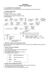
The following is a table showing how the switches are
configured to enable the various 1/0 devices to be assigned
as one or more of the LOGICAL DEVICES:
.
LOGICAL
DEVICE > > >
..
.,,*:.,
,I'
&?P3
.
,
, ..,
, ,-
1)
.
LIST
PUNCH
\
READER
,-
CONSOLE
......................................................
8 7
6 5
4 3
2 1
......................................................
................................................
Teletype > >
0 0
0 0
0 0
0 0
......................................................
Video <CRT>
0 1
x x
x x
0 f
......................................................
High Speed *
x x
0 1
0 1
x x
Paper Tape. ....
.................................
Line Printer *
x x
x x
x
x
.................................... ..............
Cassette > >
x x
1 0
1 -0
x x
......................................................
Batch Node ( * * )
x x
x x
x x
......................................................
Switch > > >
5;;~i..
;-irr
User Defined ( * )
1
1
1
1
1
1
l
1
1
o
\'
" x " means "not applicable"
NOTSS :
(*)
L:d
yrv
rr
@
(**)
t
'"
TF
<
c"
,
<
.+ ,A-tZ
'
\\
($
-/
Ad
V
-
S?
PA
The user must supply his own driver software
to interface these devices to the monitor's
operating system.
In the Batch Mode the assigned Reader becomes
the Console input and the List Device becomes
the Console output. Note that the computer
will read from the assigned Reader as if it
were a keyboard and consequently the bits on
the tape are read and interpreted as an ASCII
file rather than a binary dump or hex file as
it normally would.
&+-*
'
*.+*
a'\
/'
.'
*
%+'
$'
/
+
./.
.&I
+,a'
,
SOFTWARE CONTROL
Please note that the assignment of the 1/0
~ 2 ~ d e v i ctoe one of the LOGICAL DEVICES as is done by
,
the 8-bit dip switch can also be accomplished under
'
software control by using the ASSIGN command of the
monitor's operatinq system. For more details on
this consult the section dealing with the ZAPPLE
MONITOR.
.(
,
.
i
-
2.4
OPERATION
This part of the manual covers the operation of the
various parts of the System Monitor Board.
2.4.1
JUMP ON RESET
The System Monitor Board employs a special circuit
that allows the user to exercise control over the
computer by gaining access to the monitor system
whenever the reset button is activated.
If the board is being used in a computer which has
a front panel, the computer should be in the "RUN"
mode. If the reset is then activated, the monitor
will then sign on. The same is accomplished with
just activation of the ~ t . - _ s w i . t ~ ~ hon those
computers without front panels.
2.4.2
THE ZAPPLE MONI'TOR
The Zapple Monitor is a universal operatinq system
with
comprehensive
DEBUG
and
1/0
handling
capabilities. It contains all the needed tools to
fully debug both hardware and software as well as
support the 1/0 used by the system. It has been
instrumental in establishing the 1/0 independency
of TDL software and thereby bringing it "big
system" features not found elsewhere. -ul-of~~ our
_ _ N O 1/0
routines
..-cesi_&-n_tttsSof~re&o-ntains
whatsoever! It handles all I/O through vectors at
the begining of the program. As long as the 1/0
vectors are honored, then a Basic, Fortran, Text
Editor, etc. program does not have to be concerned
about whether the system is running a keyboard with
video monitor display, model 33, CRT terminal or
whatever. Another feature of the Zapple Monitor is
its expandability. This feature is of tremendous
use as it allows the user to attach his own
additional monitor routines at the end of the
monitor. Such routines often include 1/0 drivers.
Typical additions might be a VDM driver routine or
Tarbell cassette driver routine. Specific routines
submitted to TDL will be made available to other
users via TDL's newsletter and user's library. The
monitor also includes many useful subroutines that
may be used by user written programs. For details
on these, see the assembly listing elsewhere in
this manual.
THIS MONITOR WILL COME TO BE THE MO!
PIECE OF SOFTWARE IN YOUR SYSTEM.
COMMANDS
The following is a list of commands for the Zapple
Monitor. Precise definitions and usage notes are
covered in the next section.
A
-
ASSIGN reader, punch, console or list device
options from the console.
B
BYE (system shut down).
COMPARE the contents of memory with the reader
C
input and display any differences.
D - DISPLAY the contents of any defined memory area
in Hex.
E - END OF FILE statement generator.
area of
memory with a
F - FILL any defined
constant.
G - GOT0
an
address
and
execute.
With
breakpointing.
- HEX MAIH. Gives the sum and difference of two
Hex numbers.
* USER DEFINED.
- JUSTIFY MEMORY - a non-destructive test for
hard memory failures.
* USER DEFINED.
- LOAD a binary file.
- MOVE a defined mernory i3rea to another starting
address.
- NULLS to the punct1 devic:e.
* USER DEFINED.
- PUT ASCII characters into memory from the
keyboard.
- QUERY 1/0 ports - may output or input any value
to or from any 1/0 port.
- READ a Hex file. Performs checksum, relocating,
offsetting, etc.
S - SUBSTITUTE and/or examine any value at any
address (in hex).
T - TYPES the contents of a defined memory block in
their ASCII equivalent.
U - UNLOAD a binary tape to the punch device.
V - VERIFY the contents of a defined memory block
against that of another block and display the
differences.
W - WRITE a checksummed hex file to the punch .device.
X - EXAMINE and/or modify any or all registers
includinq the special Z-80 registers.
X I - EXAMINE and/or modify any or all of the 280's
prime registers.
Y - "Yis there". Search memory for defined byte
strinqs and display all the addresses where
they are found.
Z - " 2 end". Locate and display the highest address
in memory.
- - - - -
SMB Assembly Manual
SYSTEM MONITOR BOARD ASSEMBLY MANUAL
Copyright 1977 by
TECHNICAL DESIGN LABS, INC.
1101 State Road Bldg. H
Princeton, New Jersey 08540
CAUTION: THE SYSTEM MONITOR BOARD KIT CONTAINS SEVERAL
STATIC SENSITIVE DEVICES. DO NOT REMOVE THESE FROM THEIR
PROTECTIVE PACKAGING UNTIL THEY ARE NEEDED IN ASSEMBLY.
THEN FOLLOW THE HANDLING INSTRUCTIONS IN THIS MANUAL.
FAILURE TO HEED THIS PRECAUTION MAY RESULT 11'4PERMANENT
DAMAGE TO THESE DEVICES AND WOULD AUTOMATICALLY VOID THE
WARRANTY.
A. ABOUT BUILDING KITS
Assembling a piece of equipment and finding that it
works properly on its first checkout can be a great source
of pride
and enjoyment. Two
factors can
make this
experience possible
for
you. The
first
is quality
engineering,
which
involves
properly
designing
the
equipment, securing reliable components, and preparing clear
assembly and operating instructions. The second is careful
construction. We at TDL have taken care of the first
factor. You must be responsible for the second. To help
you in this, we offer the following construction tips, which
are considered
standard
operating
procedure
in many
commercial shops. Following these will help ensure that
your kit works properly the first time.
ALWAYS read all of the instructions before starting
to build.
Always work in a clean, well-lighted area.
Use only high quality rosin core solder of a gauge
similar to that of the leads being soldered.
Make sure that you have all the parts needed in a
given stage of construction before beginning that
stage.
Use the lowest-power soldering iron that will get
the job done. A 25 watt iron is quite adequate for
this kit.
Use a fine-point soldering iron, and keep the tip
clean and well-tinned.
Avoid overheating the PC board and components.
Before soldering a component, check to make sure
that it belongs at that place. Having to remove and
resolder a part is difficult, and it is likely that
either the board or the component will be damaged in
the process.
Apply the solder to the iron tip, the pad and the
SMB Assembly Manual
Page 11
(
)
The voltage at the
+12 volts.
cathode (band) of
(
)
The voltage at the anode (arrow) of CRll should be
-12 volts. The leads will have to be reversed on
voltmeters which
do
not
have provision for
measuring negative Turn the system's power off and
remove the board.
Install all of the following except those
asterisk, **, into their respective sockets:
POSITION
pl-R8
IC
Resistorpack
74LS367
8T97
8T97
74LS367
74LS367 '/
74LS367 ' /
74LS367 '74LS367 ',
4528
74LS02
7 . '
7 4 ~ ~ 2 ~ "
74LS02
74LS27
74LS20
4804
4804
4804
4804
,
.
A
/U9
U10
CR12 should be
with a double
I
-
*
An IC with an asterisk indicates that the label on
the silk-screen may not be exactly the same as the
above list shows. Go by the above list when there
T e c h n i c a l Memorandum
Page 1 o f 3
Date:
5
September 26, 1 9 7 7
SLDG H 1131 STATE IIOAD
ZQINCE-2N NEiV J E q S i Y 08540 1%)
921-0321
K
104
Equipment:
TDL System M o n i t o r Board
Situation:
Lack o f EMM-SEMI 4804 RAMS p r e v e n t s t h e i m p l e m e n t a t i o n
o f u s e r 1/0 r o u t i n e s .
I
I
/I
I
I
I
solution:
The e n c l o s e d r o u t i n e , when p l a c e d a t 0038 (Hex)
w i l l a l l o w t h e i m p l e m e n t a t i o n o f u s e r I/O r o u t i n e s a n d t h e 3
unused commands i n t h e m o n i t o r .
P l e a s e Note!
T h i s r o u t i n e u s e s t h e RST 7 f a c i l i t y a s d o e s t h e
break-point f e a t u r e o f t h e monitor.
I f a RST 7 i s h i t , a n d i s
not w i t h i n t h e e x t e r n a l t r a n s f e r v e c t o r a r e a o f t h e monitor,
t h i s r o u t i n e w i l l r e s t o r e a l l r e g i s t e r s and t r a p t o t h e break-point.
However, i f you u s e t h e G command w i t h more t h a n o n e a d d r e s s t h e n
t h e m o n i t o r w i l l p l a c e a jump t o i t s b r e a k - p o i n t a t 00038 ( H e x ) .
F o r r o u t i n e see t h e two a t t a c h e d s h e e t s .
C o p y r i q h t 1 9 7 7 by T e c h n i c a l D e s i g n L a b s , I n c .
P e r m i s s i o n t o copy i s g r a n t e d t o a u t h o r i z e 5 d e a l e r s o n l y a n d
o n l y f o r n o n - p r o f i t ' d i s t r i b u t i o n t o owners o f t h e r e f e r e n c e d
equipment.
i
I
II
I
TM#104
P a g e 2 of 3
9/26/77
TDL 2 8 0 ASSEMBLER V E R S I O N 1 . 2 0
SKB NO-RAM PATCH FOR EXTERNAL VECTORS
BY TOM K I R K -TDL8-12-77
.LIST
PABS
LADDR
.
.
I F THE EMM-SEMI
4 8 0 4 RAM C H I P S ARE NOT
THE
EXTERNAL TRANSFER VECTOR AT F 8 0 0 (HEX) CANNOT
BE USED.
WHEN ATTEMPTING TO IMPLEMENT A USER
PROVIDED 1/0 ROUTINE OR ONE O F THE UNUSED
COMMANDS, THE PROCESSOR W I L L EXECUTE A R S T 7
INSTRUCTION.
I F T H I S ROUTINE I S PLACED AT
0 0 3 8 (HEX) I T W I L L CAUSE A BRANCH TO THE
PROPER R O U T I N E , BASED UPON AN ADDRESS TAKEN
FROM A TABLE.
; PRESENT I N THE SYSTEM MONITOR BOARD,
;
;
;
;
;
;
;
;
.
LOC
RST7 :
0038H
JMP
; R E S T A R T 7 LOCATION
NORAM
; S P A C E F O R TRAP
NORMA:
XTHL
PUSH
MVI
CMP
JRZ
PSW
A,OF8H
H
OK
NG:
OK:
POP
XTHL
JMP
MVI
CMP
JRC
PUSH
DCR
lMvI
LXI
DAD
DIV1:
DAD
MOV
SUB
JRC
INX
MOV
DIV2:
DCR
JRNZ
;L HAS QUOTIENT
MVI
DAD
LXI
DAD
LXI
MOV
STAX
INX
INX
MOV
; G E T DUMMY RETURN
;SAVE I T
;TEST
; RETURN
PSW
;GO
OFOlEH
; TO
; TRAP
A,23H
;CHECK FOR
L
; BEYOND
NG
; TABLE
B
; F O R LATER
L
; A D J VALUE
H, 0
B, 7 0 3 H
;FOR / 3
H
;LEFT SHIFT
H
;AGAIN
A, H
;SUBTRACT
; DIVISOR
C
DIV2
;QUOTIENT 0
H
;QUOTIENT 1
H, A
;NEW D I V I D E N D
B
;DECREMENT COUNT
DIVl
; S T I L L MORE
H HAS REMAINDER
HtO
;CLEAR REMAINDER
H
;TWO BYTES
B , T A B L E ; P E R ENTRY
B
;ENTRY ADDRESS
B ,J U M P f l
A,M
; G E T LOW
B
; BYTE
H
B
ArM
;GET HIGH
TMlil04
P a g e 3 of 3
9/26/77
JUMP :
STAX
POP
POP
POP
JMP
B
B
PSW
H
.- .
; BYTE
; I T S LATER
;RESTORE
; REGISTERS
;SPLIT
T H I S TABLE I S TO B E F I L L E D WITH
; THE ADDRESSES O F THE VARIOUS 1/0 AND
; COMMAND R O U T I N E S .
; ( T H E P R E S E N T ADDRESSES ARE F O R THE T T Y . )
IFF6
90F4
1FF6
1FF6
90F4
90F4
90F4
90F4
20F5
lEFO
lEFO
lEFO
TABLE:
.WORD
.WORD
.WORD
.WORD
.WORD
.IiORD
.WORD
.WORD
.WORD
.WORD
.WORD
.WORD
OF61FH
OF490H
OF61FH
OF61FH
OF49OH
OF490H
OF490H
OF490H
OF520H
OFOlEH
OFOlEH
OFOlEH
;CONSOLE I N P U T
;CONSOLE OUTPUT
; H I G H - S P E E D READER
: U S E R READEX
; H I G H - S P E E D PUNCH
; U S E R PUNCH
;LINE PRINTER
;USER PRINTER
;CONSOLE S T A T U S
; I COMMAND
;K COMMAND
; O COMMAND
.END
+++++
DIVl
NG
RST7
0054
0042
0038
SYMBOL TABLE
DIV2
NORAM
TABLE
005B
003B
0074
+++++
JUMP
OK
0071
0047
Technical Memorandum
Page 1 of 1
Date: 1 0 / 1 9 / 7 7
-
>€ARCH PARK BLGG H 1101 STATE ROAD
921.0321
PRINCETCN. NEW JERSEY 08540 (M)
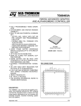
System Monitor Board
Situation:
Solution:
Reset will not restart monitor, and will cause programs
to blow-up.
The reset circuitry uses a CMOS one-shot CD4528,
chip U9. The cassette circuit also uses the 4528,
U35. But for various reasons involving response
time, only one manufacturer's 4525 has been found
to be satisfactory for U9, the Fairchild Chip. Due
to the short supplies of Fairchild CMOS, only one
is packed in each System Monitor Board. The SMB
owner should make certain that the U9 is the Fairchild, and not some 0th-er brand chip. Any brand
4528 will suffice forkJ35..
\-./
Copyright 1977 by Technical Design Labs, Inc.
Permission to copy is granted to authorized dealers only and
only for non-profit distribution to owners of the referenced
equipment.
/-
i
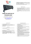
~7v.1
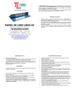
i ~ m ct ~: .
I1
Sitrla ti.97 :
TnI, SMi? h o a r d :i.sr:cl r i t F ! A S R - 7 3 'I'TY for tape reader.
!
~ I ~ c Y cA
? s c ~ ~ m b l c:!PC
r ,l:. r?
ceontrollcd r e a d - c r
I
.
I
1
1I
I
.A
I
Sol:lti.cn :
I
I
The circuit. .hel_otlt r i l l . zal?F;e t 9 e ZiT3-33 to m a d tap?
1
u n d e r c o n t r o l Crcm c?rnp-t-er, w i t - : ~ o u t f u r t h e r mod:; to
thc so.Ctwarc.
s:i7:e ta ~ o t et h . 7 rnc,c?i?ic:?tion to the
.
S?.tI?
C o n y r l ~ h t 1 9 7 7 by T ? c f ~ n i r a l I ? s ? s ? . c_~.P',a.hs, Inc.
P ~ r ~ i s c i"
~,no ~ is
y ~rsntcic'. t 3 ; i ~ t h ~ ? r i ? e(Jbalezs
Z
~ ~ 2 3. 1
~ ~
d
on:'i o r r?on-.?rc FLt. 3.i _ ; t r i Y : l t ~ O SL-C) O L I I I ~ ~ Tof
S
the ) ~ e f t ~ r c ~ c , ? d
equip~ent.
I
I