1
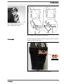
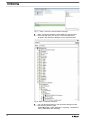
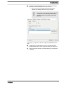
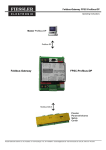
Installation and configuration manual
DXCa CANopen – PROFIBUS-DP-Gateway
V1.2
A1241
Target group: Programmers and trained users
Please carefully read these operating instructions before use! · Do not discard!
The operator shall be liable for any damage caused by installation or operating errors!
Technical changes reserved.
985473
These instructions are only valid in conjunction with the instructions DULCOMARIN® II BA DC 081 07/12 EN
ProMinent Dosiertechnik GmbH
Im Schuhmachergewann 5 - 11
69123 Heidelberg
Telephone: +49 6221 842-0
Fax: +49 6221 842-419
email: [email protected]
Internet: www.prominent.com
985473, 1, en_GB
© 2012
2
Supplemental instructions
General non-discriminatory approach
In order to make it easier to read, this document uses the male
form in grammatical structures but with an implied neutral sense. It
is aimed equally at both men and women. We kindly ask female
readers for their understanding in this simplification of the text.
Supplementary information
Please read the supplementary information in its entirety.
The following are highlighted separately in the document:
n Enumerated lists
Instructions
ð Outcome of the instructions
Information
This provides important information relating to the cor‐
rect operation of the device or is intended to make
your work easier.
Safety information
The safety information includes detailed descriptions of the haz‐
ardous situation.
3
Table of contents
Table of contents
4
1
Introduction........................................................................... 5
1.1 Technical data.............................................................. 6
2
Security................................................................................. 8
2.1 Duty to read the user manual....................................... 8
2.2 Exclusion of plausibility checking of the setpoints........ 8
2.3 Explanation of the safety information............................ 9
2.4 Users' Qualifications .................................................. 10
3
Commissioning................................................................... 12
3.1 Connectors/fitting ....................................................... 12
3.2 Commissioning example, using Step 7....................... 14
4
Description of the data objects............................................
4.1 Actual values..............................................................
4.2 Control values.............................................................
4.3 Status slave................................................................
4.4 Error messages..........................................................
5
PROFIBUS – acyclic data traffic (control values and
Pause/ECO!Mode active)................................................... 30
5.1 Setpoints..................................................................... 30
5.2 Addressing of acyclic values (read/write)................... 33
6
LEDs and addressing .........................................................
6.1 SYS-LED....................................................................
6.2 BF1-LED.....................................................................
6.3 SF LED.......................................................................
6.4 BF2-LED.....................................................................
6.5 RUN-LED....................................................................
7
Troubleshooting.................................................................. 46
8
Appendix............................................................................. 47
8.1 PROFIBUS DP interface............................................. 47
9
Index................................................................................... 49
20
20
24
27
28
43
43
44
44
44
45
Introduction
1
Introduction
The document is aimed at programmers and personnel
who are involved with planning and commissioning.
This document contains a description of the DXCa-PROFIBUSCAN gateway for communication with the DULCOMARIN® II. The
document should also assist in commissioning the DXCa-PRO‐
FIBUS gateway. Alongside the description of the hardware and
software components, this document also contains a typical project
created using the development environment [Step 7] from Sie‐
mens. The document is aimed at programmers and personnel who
are involved with planning and commissioning.
This software manual is only valid in combination with the DXCa
gateway described in this document. The DXCa-Gateway may only
be used with DULCOMARIN® II. The content of this document has
been checked for agreement with the described hardware and soft‐
ware. Nevertheless deviations cannot be excluded. Complete
agreement cannot therefore be guaranteed.
Revision history
Revision
Date
Name
Chapter
Revision
1
12/01/2012
FR
All
Document created.
1.1
09/05/2012
FR
7
[ECO!Mode] and [Pause active] were extended.
1.2
25/05/2012
FR
6
Actual and control values matched to GSD revision 2.
Table ‘ Addressing of acyclic values ’ has been
expanded.
5
Introduction
Reference to hardware, software and
firmware
Hardware
Device
Revision
DXCa-PROFIBUS-CAN-Gateway
1
DULCOMARIN® II
001
Software
Software
Version
HERMES flasher
1
Firmware
Firmware
Firmware version
For the hardware
PROFIBUS protocol
2.3.x.x
DXCa-PROFIBUS-Gateway
Gateway firmware
1
DXCa-PROFIBUS-Gateway
Firmware DULCOMARIN® II
From 3022
DULCOMARIN® II
Firmware
Firmware version
For the hardware
GSD file
2.0.0
DXCa-PROFIBUS-Gateway
GSD file
1.1 Technical data
Properties PROFIBUS-DP interface
Description
Parameter
Maximum input data
244 Byte
Maximum output data
244 Byte
Baud rate
9.6 kBit/s
19.2 kBit/s
31.25 kBit/s
45.45 kBit/s
93.75 kBit/s
187.5 kBit/s
500 kBit/s
1.5 MBit/s
3 MBit/s
6 MBit/s
12 MBit/s
6
Introduction
Description
Parameter
Interface type
Potential-free RS-485 interface
Connector
D-sub port, 9 pin
Auto-detection
yes
Characteristic data DXCa-Gateway
Description
Parameter
Power supply
24V DC
Typical power consumption
approx. 500mA
Max. number of measured values
116
Weight
250g
Dimensions (L x W x H)
117.2 x 45 x 113.5 (mm)
ROHS
yes
CE mark
yes
IP rating
IP20
7
Security
2
Security
This document plus all accompanying texts were
written for use by briefed and trained specialist per‐
sonnel. When using this product, all safety instructions
plus the applicable regulations must be observed. The
user must ensure adherence to the legal conditions.
Intended use
The DXCa-Gateway described in this document represents a PRO‐
FIBUS based interface to the DULCOMARIN® II made by ProMi‐
nent®. The DXCa-Gateway may only be operated in conjunction
with the named device and as described in this document. The
DXCa gateway was designed solely to create a connection
between the PROFIBUS master and the DULCOMARIN® II.
Incorrect use
It is strictly forbidden to use the DXCa gateway in the following
areas:
n for military purposes or in weapons systems
n for the design, construction, maintenance or operation of
nuclear plants
n in flight safety systems, air traffic or flight communications sys‐
tems
n in life support systems
n in systems in which incorrect functioning of the gateway could
result in physical injuries or fatal injuries.
You are advised that the DXCa gateway was not created for use in
dangerous environments, that require fail-safe control mecha‐
nisms. The use of the DXCa gateway in such an environment is at
your own risk, any liability for damage or losses arising from imper‐
missible use is excluded.
2.1 Duty to read the user manual
Before the installation and use of the DXCa gateway described in
this document, you must read and understand all instructions to
avoid damage.
2.2 Exclusion of plausibility checking of the setpoints
At this point it is expressly pointed out that the DXCa PROFIBUS
CAN gateway does not carry out any plausibility testing of the fedthrough parameters and setpoints.
Checking, alarming or correction of these setpoints does not take
place and is also technically not provided for. In systems, in which
incorrect operation or incorrect setpoint specifications may under
certain circumstances cause damage, the responsibility is that of
the operator, this applies particularly where there is a risk of impair‐
ment to health.
The user/operator must therefore ensure that they personally are
adhering to critical parameters by carrying out regular, manual con‐
trol measurements.
8
Security
2.3 Explanation of the safety information
Introduction
These operating instructions provide information on the technical
data and functions of the product. These operating instructions pro‐
vide detailed safety information and are provided as clear step-bystep instructions.
The safety information and notes are categorised according to the
following scheme. A number of different symbols are used to
denote different situations. The symbols shown here serve only as
examples.
DANGER!
Nature and source of the danger
Consequence: Fatal or very serious injuries.
Measure to be taken to avoid this danger
Danger!
–
Denotes an immediate threatening danger. If this is
disregarded, it will result in fatal or very serious
injuries.
WARNING!
Nature and source of the danger
Possible consequence: Fatal or very serious injuries.
Measure to be taken to avoid this danger
Warning!
–
Denotes a possibly hazardous situation. If this is
disregarded, it could result in fatal or very serious
injuries.
CAUTION!
Nature and source of the danger
Possible consequence: Slight or minor injuries, mate‐
rial damage.
Measure to be taken to avoid this danger
Caution!
–
Denotes a possibly hazardous situation. If this is
disregarded, it could result in slight or minor inju‐
ries. May also be used as a warning about material
damage.
NOTICE!
Nature and source of the danger
Damage to the product or its surroundings
Measure to be taken to avoid this danger
Note!
–
Denotes a possibly damaging situation. If this is
disregarded, the product or an object in its vicinity
could be damaged.
9
Security
Type of information
Hints on use and additional information
Source of the information, additional measures
Information!
–
Denotes hints on use and other useful information.
It does not indicate a hazardous or damaging sit‐
uation.
2.4 Users' Qualifications
WARNING!
Danger of injury with inadequately qualified personnel!
If inadequately qualified personnel work on the unit or
loiter in the hazard zone of the unit, this could result in
dangers that could cause serious injuries and material
damage.
–
–
All work on the unit should therefore only be con‐
ducted by qualified personnel.
Unqualified personnel should be kept away from
the hazard zone.
Training
Definition
instructed personnel An instructed person is deemed to be a
person who has been instructed and, if
required, trained in the tasks assigned to
him/her and possible dangers that could
result from improper behaviour, as well as
having been instructed in the required pro‐
tective equipment and protective meas‐
ures.
10
Trained user
A trained user is a person who fulfills the
requirements made of an instructed person
and who has also received additional
training specific to the system from ProMi‐
nent or another authorised distribution
partner.
Technical experts
A technical expert is deemed to be a
person who is able to assess the tasks
assigned to him and recognize possible
hazards based on his/her technical training
and experience, as well as knowledge of
pertinent regulations.
Security
Training
Definition
Trained qualified
personnel
A qualified employee is deemed to be a
person who is able to assess the tasks
assigned to him and recognize possible
hazards based on his/her training, knowl‐
edge and experience, as well as knowl‐
edge of pertinent regulations. The assess‐
ment of a person's technical training can
also be based on several years of work in
the relevant field.
Electrician
Electricians are deemed to be people, who
are able to complete work on electrical
systems and recognize and avoid possible
hazards independently based on their
technical training and experience, as well
as knowledge of pertinent standards and
regulations.
Electricians should be specifically trained
for the working environment in which they
are employed and know the relevant
standards and regulations.
Electricians must comply with the provi‐
sions of the applicable statutory directives
on accident prevention.
Customer service
department
Customer Service department refers to
service technicians, who have received
proven training and have been authorised
by ProMinent to work on the system.
Note for the system operator
The pertinent accident prevention regulations, as well
as all other generally acknowledged safety regulations,
must be adhered to!
11
Commissioning
3
Commissioning
During commissioning of the DXCa
gateway, please proceed as follows:
1.
Fit the DXCa gateway on a standard top hat rail
2.
Provide the 24V DC power supply
3.
Connect the DXCa gateway to the DULCOMARIN® II using a
CAN M12 connection cable.
4.
Connect the DXCa gateway to the PLC using a PROFIBUS
cable and corresponding D-sub 9 pin plug
5.
Set the desired addresses for the CAN bus and PROFIBUS.
6.
Create a configuration and load the program in the PLC
memory.
3.1 Connectors/fitting
Klick
2
90°
3
1
A1219
Fig. 1: The DXCa gateway is designed for assembly on standard
top hat rail configurations (e.g. DIN EN 60715, steel, 2000 mm,
galvanized)
12
Commissioning
A1221
Fig. 2: Fitting / removal of the con‐
nector plug (detailed view)
A1220
Fig. 3: Fitting / removal of the connector plug
Power supply
The DXCa gateway has two connection terminals for+24 V and 0 V
(jumpered on the circuit board).
+24V
0V
A1222
Fig. 4: Front view of DXCa gateway (power supply)
13
Commissioning
3.2 Commissioning example, using Step 7
In the selection menu that appears, navigate to the storage loca‐
tion of the GSD file and select it (see figure 6: Step 7 Installing a
GSD file (selection menu)).
GSD file
You can find the GSD file on the enclosed data
medium or in the download area under
http://www.prominent.de/Service/DownloadService.aspx
The commissioning example shown in this chapter takes place
under Siemens' Step 7 development environment. The incorpora‐
tion or planning of the DXCa gateway via the GSD file takes place
under the development environments of other manufacturers anal‐
ogously to the procedure described here. A pre-configured project
including a PLC and fully functional PROFIBUS are prerequisites
for this part of the document.
14
Commissioning
A1223
Fig. 5: Step 7 Installing a GSD file
1.
The properties as well as all of the necessary information of
the DXCa gateway are described in the GSD file. The GSD
file must be installed in the engineering system for planning
of the DXCa gateway. In the Step 7 hardware manager this
takes place under the menu option:
[Extras -> Install GSD file]
A1224
Fig. 6: Step 7 Installing a GSD file (selection menu)
2.
In the selection menu that appears, navigate to the storage
location of the GSD file and select this GSD file.
15
Commissioning
A1225
Fig. 7: : Step 7 overview of the hardware manager
3.
After successful installation of the GSD file, start the hard‐
ware manager from your project. The DXCa gateway is
located in the hardware catalogue on the right-hand side.
A1226
Fig. 8: Step 7 hardware catalogue
4.
You can find the gateway in the hardware catalogue under
the following directory path:
[PROFIBUS-DP > Other DEVICES > Gateway > ProMinent >
DXCA PROFIBUS-DP Gateway]
16
Commissioning
5.
With the mouse key pressed you can now drag the DXCa
gateway to the PROFIBUS in the left window.
ð Once you have successfully positioned the DXCa
gateway, the dialogue shown in Fig. 9 appears.
The number set in the field [Address] MUST
correspond to the [Address] of the rotary
encoding switch on the front of the DXCa
gateway.
A1227
Fig. 9: Step 7 properties of the DXCa gateway PROFIBUS inter‐
face
6.
Under the point [Subnetwork], you must select the PRO‐
FIBUS network to be used, using the speed set in the PLC.
7.
After successful selection, quit the dialogue by pressing the
[OK] key
17
Commissioning
A1228
Fig. 10: The Step 7 DXCa gateway on the PROFIBUS
8.
The Step 7 DXCa gateway is successfully connected to the
PROFIBUS
ð Henceforth you can now configure the Step 7 DXCa
gateway using measured values. The configuring of the
Step 7 DXCa gateway using measured values is illus‐
trated in the following figure.
A1229
Fig. 11: Step 7 DXCa gateway, configuring measured values
9.
Under the already described hardware catalogue, you can
now select the desired measured values. To do this, you
must simply drag the desired measured value to the slots of
the DXCa gateway.
You can change or adapt the addressing (input
addresses) and the sequence of the measured
values according to your own needs.
You must however ensure that at least one
measured value is present at the slots of the
DXCa gateway, as otherwise the PLC program
cannot be compiled.
18
Commissioning
10.
After you have populated the DXCa gateway with the desired
measured values, you can compile the program and load it in
the PLC memory.
19
Description of the data objects
4
Description of the data objects
4.1 Actual values
Remarks
After starting DULCOMARIN® II all actual values are
only available on the PROFIBUS after 130 seconds.
Non-available or incorrect measured values are shown
as [0x7FFF = 32767].
Variables pH measured value, Pool 1... 16
Measured value
PROFIBUS input value
(range)
Converted measured value Unit
Variables pH measured value,
Pool 1... 16
0 ... 1400
Range: 0 ... 14.00
--
Example: 720 = 7.20 pH
(pH actual value)
Variables redox measured value, Pool 1... 16
Measured value
PROFIBUS input value (range) Converted measured value
Unit
Variables redox measured
value, Pool 1 ... 16
-1200 ... +1200
-1200 ... 1200 mV
mV
(Redox actual value)
Variables temperature measured value, Pool 1... 16
Measured value
PROFIBUS input value (range)
Converted measured
value
Unit
Variables temperature meas‐
ured value, Pool 1... 16
0 ... 1200
Range: 0 ... 120°C
°C
(Temperature actual value)
20
Example: 130 = 13.0 °C
Description of the data objects
The interpretation of the data changes dependent on
the identity code. The following data are consecutively
numbered starting with number 4 and thus do not have
the actual names of their user data.
Channel 4 measured value variables, Pool 1 ... 16
Measured value Sensor type
DXCa iden‐
tity code
PROFIBUS input
value (range)
Converted measured value
Unit
S, C, D
0 to 1000
Range 0 ... 10.00 ppm
ppm
Channel 4
measured value
variables, Pool
1 ... 16
(Channel 4
actual value)
Chlorine
CLE 3
Example: 200 = 2.00 ppm
0 ... 20000
Range 0 ... 200 ppm
ppm
Example: 10000 = 100 ppm
CGE
S, D
0 - 1000
Range 0 ... 10.00 ppm
ppm
Example: 200 = 2.00 ppm
CLE 3.1
0 to 1000
Range 0 ... 10.00 ppm
ppm
Example: 200 = 2.00 ppm
Free chlorine
0 to 1000
Range 0 .. 10.00 ppm
ppm
Example: 200 = 2.00 ppm
Bromine
0 to 1000
Range 0 ... 10.00 ppm
ppm
Example: 200 = 2.00 ppm
ClO2
CDR
S, D
0 to 200
Range 0 ... 2.00 ppm
ppm
Example: 50 = 0.50 ppm
21
Description of the data objects
Channel 5 measured value variables, Pool 1 ... 16
Measured value Sensor type
DXCa identity
code
PROFIBUS input
value (range)
Converted measured value
Unit
0 ... 1000
Range 0 ... 10.00 ppm
ppm
"Use"
Channel 5
measured value
variables, Pool
1 ... 16
(Channel 5
actual value)
Cl
CLE 3
C
Example: 200 = 2.00 ppm
0 ... 20000
Range 0 ... 200 ppm
ppm
Example: 10000 = 100 ppm
Total chlorine
CTE
D
0 ... 1000
Range 0 ... 10.00 ppm
ppm
Example: 200 = 2.00 ppm
Combined
chlorine
CTE
ClO2-
CLT
S
0 ... 1000
Range 0 ... 10.00 ppm
Example: 200 = 2.00 ppm
S, D
0 ... 200
Range 0 ... 2.00 ppm
Example: 50 = 0.50 ppm
22
ppm
ppm
Description of the data objects
Channel 6 measured value variables, Pool 1 ... 16
Measured
value
Sensor type
DXCa identity PROFIBUS input
code
value (range)
Converted measured value
Unit
Range 0 ... 10.00 ppm
ppm
"Use"
Channel 6
measured
value variables,
Pool 1 ... 16
(Channel 6
actual value)
Total chlorine
CTE
S
0 ... 1000
Example: 200 = 2.00 ppm
Combined
chlorine
CTE
D
0 ... 1000
Range 0 ... 10.00 ppm
ppm
Example: 200 = 2.00 ppm
Channel 7 measured value variables, Pool 1 ... 16
Measured value
PROFIBUS input value (range)
Converted measured
value
Unit
Converted measured
value
Unit
PROFIBUS input value (range)
Converted measured
value
Unit
I1 (edit mode)
0 ... 9999
Dependent on the edited value in the
I module
Q
0 ... 9999
see device formatting
Channel 7 measured value var‐
iables, Pool 1 ... 16
(Channel 7 actual value)
Ht. above sea level
Channel 8 measured value variables, Pool 1 ... 16
Measured value
PROFIBUS input value (range)
Channel 8 measured value var‐
iables, Pool 1 ... 16
(Channel 8 actual value)
CANopen turbidity sensor
Channel 9 measured value variables, Pool 1 ... 16
Measured value
Channel 9 measured value var‐
iables, Pool 1 ... 16
(Channel 9 actual value)
m³/h, l/h
23
Description of the data objects
Channel 10 measured value variables, Pool 1 ... 16
Measured value
PROFIBUS input value (range)
Converted measured
value
Unit
Channel 10 measured value
variables, Pool 1 ... 16
(Channel 10 actual value)
I2 (edit mode)
0 ... 9999
mA
Ammonia (NH3)
0 ... 9999
ppm, mg/l
Hydrogen peroxide (H2O2)
0 ... 9999
ppm, mg/l
Peracetic acid (PES)
0 ... 9999
ppm, mg/l
Conductive conductivity
0 ... 9999
µS/cm,
mS/cm, S/
cm
ClO2
0 ... 9999
ppm, mg/l
O2
0 ... 9999
ppm, mg/l
Channel 11 measured value variables, Pool 1 ... 16
Measured value
PROFIBUS input value (range)
Converted measured
value
Unit
Channel 11 measured value
variables, Pool 1 ... 16
(Channel 11 actual value)
I3 (edit mode)
mA
PES
0 ... 9999
ppm/mg/l
Temperature
0 ... 9999
°C
ClO2-
0 ... 9999
ppm/mg/l
UV intensity (UV)
0 ... 9999
W/m²,
mW/cm²
Turbidity
0 ... 9999
FNU,
NTU,
FTU,
FAU, EBC
4.2 Control values
Remarks
After starting DULCOMARIN® II all control values are
only available on the PROFIBUS after 130 seconds.
Non-available or incorrect measured values are shown
as [0x7FFF = 32767].
24
Description of the data objects
The interpretation of the data changes dependent on
the identity code. The following data are consecutively
numbered starting with number 4 and thus do not have
the actual names of their user data.
pH control output, Pool 1... 16
Measured value
PROFIBUS input value (range)
Converted measured
value
Unit
pH control output, Pool
1... 16
-1000 ... 0 ... +1000
Range: 0 ... 14.00
%
(pH control value)
Example: 720 = 7.20 pH
Redox control output, Pool 1... 16
Measured value
PROFIBUS input value (range)
Converted measured
value
Unit
Redox control output, Pool
1... 16
-1000 ... 0 ... +1000
-1200 to 1200 mV
%
(redox control value)
Temperature control output, Pool 1... 16
Measured value
PROFIBUS input value (range)
Converted measured
value
Unit
Temperature control output,
Pool 1... 16
0 ... 1000
Range: 0 ...120°C
°C
(Temperature control value)
Example: 130 = 13.0 °
25
Description of the data objects
Channel 4 control output, Pool 1 ... 16
Measured value
PROFIBUS input value (range)
Converted measured
value
Unit
Channel 4 control output,
Pool 1 ... 16
Chlorine
0 ... 1000
%
Bromine
ClO2
Channel 5 control output, Pool 1 ... 16
Measured value
PROFIBUS input value (range)
Converted measured
value
Unit
Channel 5 control output,
Pool 1 ... 16
Combined chlorine
-1000 ... 0
%
ClO2
-1000 ... 0
%
Channel 6 control output, Pool 1 ... 16
Measured value
PROFIBUS input value (range)
Converted measured
value
Unit
Channel 6 control output,
Pool 1 ... 16
Ht. above sea level
0 ... 1000
%
Channel 7 control output, Pool 1 ... 16
Measured value
PROFIBUS input value (range)
Converted measured
value
Unit
Channel 7 control output,
Pool 1 ... 16
Flocculation
0 ... 1000
%
Channel 8 control output, Pool 1 ... 16
Measured value
PROFIBUS input value (range)
Converted measured
value
Unit
Channel 8 control output,
Pool 1 ... 16
Ht. above sea level
26
0 ... 1000
%
Description of the data objects
Channel 9 control output, Pool 1 ... 16
Measured value
PROFIBUS input value (range)
Converted measured
value
Unit
Channel 9 control output,
Pool 1 ... 16
Ht. above sea level
%
Channel 10 control output, Pool 1 ... 16
Measured value
PROFIBUS input
value (range)
Converted
measured
value
Unit
Channel 10 con‐
trol output, Pool
1 ... 16
(Channel 10
control value)
I2 (edit mode)
0 ... 1000
%
Ammonia (NH3)
0 ... 1000
%
Hydrogen per‐
oxide (H2O2)
0 ... 1000
%
Peracetic acid
(PES)
0 ... 1000
%
Conductive con‐
ductivity
0 ... 1000
%
ClO2
0 ... 1000
%
O2
0 ... 1000
%
Channel 11 control output, Pool 1 ... 16
Measured value
PROFIBUS input value (range)
Converted measured
value
Unit
Channel 11 control output,
Pool 1 ... 16
Ht. above sea level
%
4.3 Status slave
Status slave
No.
Description
Address / byte offset
1
Status CAN-bus connection
0
0 = OK
1 = no CAN connection / error
2
SW revision controller
1
Example: 123 = V1.23
27
Description of the data objects
No.
Description
Address / byte offset
3
HW revision DXCa-Gateway
2
Example: 100 = V1.00
4
Source of the CAN-ID
3
1 = front rotary encoding switch
2 = specification by DULCOMARIN® II
5
CAN bus ID (identification number)
4
6
Error code
5
0 = OK
1 = internal error
7
Ht. above sea level
6
8
Ht. above sea level
7
4.4 Error messages
Error messages
No.
Description
1
Error in Pool 1 (32 Bit)
…
16
Error in Pool 16 (32 Bit)
Decoding of the error messages
pH actual value channel 1 = 0x00000001 pH measured value
bit: 0
invalid
pH actual value channel 1 = 0x00000002 pH measured value
bit: 1
min.
pH actual value channel 1 = 0x00000004 pH measured value
bit: 2
max.
28
Channel 2 bit: 3
= 0x00000008 measured value
invalid
Channel 2 bit: 4
= 0x00000010 measured value min.
Channel 2 bit: 5
= 0x00000020 measured value max.
Channel 3 bit: 6
= 0x00000040 measured value
invalid
Channel 3 bit: 7
= 0x00000080 measured value min.
Channel 3 bit: 8
= 0x00000100 measured value max.
Channel 4 bit: 9
= 0x00000200 measured value
invalid
Channel 4 bit: 10
= 0x00000400 measured value min.
Channel 4 bit: 11
= 0x00000800 measured value max.
Description of the data objects
Channel 5 bit: 12
= 0x00001000 measured value
invalid
Channel 5 bit: 13
= 0x00002000 measured value min.
Channel 5 bit: 14
= 0x00004000 measured value max.
Channel 10 bit: 15
= 0x00008000 measured value
invalid
Channel 10 bit: 16
= 0x00010000 measured value min.
Channel 10 bit: 17
= 0x00020000 measured value max.
Channel 11 bit: 18
= 0x00040000 measured value
invalid
Channel 11 bit: 19
= 0x00080000 measured value min.
Channel 11 bit: 20
= 0x00100000 measured value max.
Bit 21
= 0x00200000 sample water error
Free bit: 22
= 0x00400000
Free bit: 23
= 0x00800000
Free bit: 24
= 0x01000000
Free bit: 25
= 0x02000000
DXMaA bit: 26
= 0x04000000 error
DXMaR bit: 27
= 0x08000000 control valve not
ready
DP1 bit: 28
= 0x10000000 metering pump error
active
DP2 bit: 29
= 0x20000000 metering pump error
active
DP3 bit: 30
= 0x40000000 metering pump error
active
DP4 bit: 31
= 0x80000000 metering pump error
active
No fault or error
= 0x00000000
29
PROFIBUS – acyclic data traffic (control values and Pause/ECO!Mode active)
5
PROFIBUS – acyclic data traffic (control values and Pause/
ECO!Mode active)
The following control values are only available to you
via acyclic PROFIBUS traffic (DPV1).
5.1 Setpoints
The interpretation of the data changes dependent on
the identity code. The following data are consecutively
numbered starting with number 4 and thus do not have
the actual names of their user data.
Remarks
After starting DULCOMARIN® II all control values are
only available on the PROFIBUS after 130 seconds.
pH setpoint, pool 1 to 16
Measured
value
PROFIBUS input value
(range)
Converted measured
value
Unit
Access
pH setpoint
0 ... 1400
Range: 0 ... 14.00
---
Read/write
Pool 1 to 16
Example: 720 = 7.20 pH
Redox setpoint, pool 1 to 16
Measured value
PROFIBUS input
value (range)
Converted meas‐
ured value
Unit
Access
Redox setpoint
-1200 ... +1200
-1200 ... 1200 mV
mV
Read/write
Pool 1 to 16
Temperature setpoint, pool 1 to 16
Measured
value
PROFIBUS Converted
input value measured
(range)
value
Tempera‐
ture set‐
point
0 ... 1200
Pool 1 to
16
30
Unit
Range: 0 ... °C
120°C
Example:
130 = 13.0
°C
Access
Read/write
PROFIBUS – acyclic data traffic (control values and Pause/ECO!Mode active)
Channel 4 setpoint, Pool 1 ... 16
Measured value Sensor type
DXCa iden‐
tity code
PROFIBUS input
value (range)
Converted measured value
Channel 4 set‐
point, Pool
1 ... 16
Chlorine
Access
Read/
write
CLE 3
S, C, D
0 to 1000
Range 0 ... 10.00 ppm
Example: 200 = 2.00 ppm
0 ... 20000
Range 0 ... 200 ppm
Example: 10000 = 100 ppm
CGE
S, D
0 - 1000
Range 0 ... 10.00 ppm
Example: 200 = 2.00 ppm
CLE 3.1
0 to 1000
Range 0 ... 10.00 ppm
Example: 200 = 2.00 ppm
Free chlorine
0 to 1000
Range 0 .. 10.00 ppm
Example: 200 = 2.00 ppm
Bromine
0 to 1000
Range 0 ... 10.00 ppm
Example: 200 = 2.00 ppm
ClO2
CDR
S, D
0 to 200
Range 0 ... 2.00 ppm
Example: 50 = 0.50 ppm
Channel 5 setpoint, Pool 1 ... 16
Measured value Sensor type
DXCa identity
code
PROFIBUS input
value (range)
Converted measured value
Access
"Use"
Channel 5 set‐
point, Pool
1 ... 16
Cl
Read/
write
CLE 3
C
0 ... 1000
Range 0 ... 10.00 ppm
Example: 200 = 2.00 ppm
0 ... 20000
Range 0 ... 200 ppm
Example: 10000 = 100 ppm
Total chlorine
CTE
D
0 ... 1000
Range 0 ... 10.00 ppm
Example: 200 = 2.00 ppm
Combined
chlorine
CTE
ClO2-
CLT
S
0 ... 1000
Range 0 ... 10.00 ppm
Example: 200 = 2.00 ppm
S, D
0 ... 200
Range 0 ... 2.00 ppm
Example: 50 = 0.50 ppm
31
PROFIBUS – acyclic data traffic (control values and Pause/ECO!Mode active)
Channel 6 setpoint, Pool 1 ... 16
Measured
value
Sensor type
DXCa identity PROFIBUS input
code
value (range)
Converted measured value
Acces
s
"Use"
Channel 6 set‐
point, Pool
1 ... 16
Read/
write
Ht. above sea
level
Channel 7 setpoint, Pool 1 ... 16
Measured value
PROFIBUS input value (range)
Converted measured
value
Channel 7 setpoint, Pool
1 ... 16
Access
Read/write
Ht. above sea level
Channel 8 setpoint, Pool 1 ... 16
Measured value
PROFIBUS input value (range)
Converted measured
value
Channel 8 setpoint, Pool
1 ... 16
Access
Read/write
Ht. above sea level
Channel 9 setpoint, Pool 1 ... 16
Measured value
PROFIBUS input value (range)
Converted measured
value
Channel 9 setpoint, Pool
1 ... 16
Access
Read/write
Ht. above sea level
Channel 10 setpoint, Pool 1 ... 16
Measured value
PROFIBUS input value (range)
Channel 10 setpoint, Pool 1 ...
16
Converted measured
value
Access
Read/
write
I2 (edit mode)
0 ... 9999
mA
Ammonia (NH3)
0 ... 9999
ppm, mg/l
Hydrogen peroxide (H2O2)
0 ... 9999
ppm, mg/l
Peracetic acid (PES)
0 ... 9999
ppm, mg/l
Conductive conductivity
0 ... 9999
µS/cm,
mS/cm, S/
cm
32
PROFIBUS – acyclic data traffic (control values and Pause/ECO!Mode active)
Measured value
PROFIBUS input value (range)
Converted measured
value
Access
ClO2
0 ... 9999
ppm, mg/l
O2
0 ... 9999
ppm, mg/l
Channel 11 setpoint, Pool 1 ... 16
Measured value
PROFIBUS input value (range)
Converted measured
value
Channel 11 setpoint, Pool
1 ... 16
Access
Read/write
Ht. above sea level
Pause, active
Measured value
PROFIBUS input value (range)
Converted measured
value
Pause, Pool 1 ... 16
Access
Read/write
Pause, active = 1
Pause, inactive = 0
Under pause inactive, the corresponding field contains a [0].
ECO!Mode, active:
Measured value
PROFIBUS input value (range)
ECO!Mode, Pool 1 ... 16
Converted measured
value
Access
Read/write
ECO!Mode, active = 1
ECO!Mode, inactive = 0
Under ECO!Mode inactive, the corresponding field contains a [0].
5.2 Addressing of acyclic values (read/write)
The values listed in chapter Ä Chapter 5.1 ‘Setpoints’ on page 30
can only be achieved by acyclic data transfer. All acylic setpoints
are addressed via slot and index. Each setpoint must be trans‐
ferred in an independent telegram. The DXCa gateway does not
check the setpoints to be written for plausibility. However the
addressing (slot, index and data length) are checked. If the
addressing does not agree with the addressing in the following
table, the DXCa gateway reacts and sends a configuration error in
the standard diagnosis.
33
PROFIBUS – acyclic data traffic (control values and Pause/ECO!Mode active)
Due to the high number of measured values, all setpoints can be
addressed via slot [0] and the respective index.
Slot and indexes of the acylic data objects
No.
Slot
Index
Data object
Length
Type
Access
1
0
1
pH setpoint pool 1
2 Byte
INT16
Read / write
2
0
2
pH setpoint pool 2
2 Byte
INT16
Read / write
3
0
3
pH setpoint pool 3
2 Byte
INT16
Read / write
4
0
4
pH setpoint pool 4
2 Byte
INT16
Read / write
5
0
5
pH setpoint pool 5
2 Byte
INT16
Read / write
6
0
6
pH setpoint pool 6
2 Byte
INT16
Read / write
7
0
7
pH setpoint pool 7
2 Byte
INT16
Read / write
8
0
8
pH setpoint pool 8
2 Byte
INT16
Read / write
9
0
9
pH setpoint pool 9
2 Byte
INT16
Read / write
10
0
10
pH setpoint pool 10
2 Byte
INT16
Read / write
11
0
11
pH setpoint pool 11
2 Byte
INT16
Read / write
12
0
12
pH setpoint pool 12
2 Byte
INT16
Read / write
13
0
13
pH setpoint pool 13
2 Byte
INT16
Read / write
14
0
14
pH setpoint pool 14
2 Byte
INT16
Read / write
15
0
15
pH setpoint pool 15
2 Byte
INT16
Read / write
16
0
16
pH setpoint pool 16
2 Byte
INT16
Read / write
17
0
17
Redox setpoint pool 1
2 Byte
INT16
Read / write
18
0
18
Redox setpoint pool 2
2 Byte
INT16
Read / write
19
0
19
Redox setpoint pool 3
2 Byte
INT16
Read / write
20
0
20
Redox setpoint pool 4
2 Byte
INT16
Read / write
21
0
21
Redox setpoint pool 5
2 Byte
INT16
Read / write
22
0
22
Redox setpoint pool 6
2 Byte
INT16
Read / write
23
0
23
Redox setpoint pool 7
2 Byte
INT16
Read / write
24
0
24
Redox setpoint pool 8
2 Byte
INT16
Read / write
25
0
25
Redox setpoint pool 9
2 Byte
INT16
Read / write
26
0
26
Redox setpoint pool 10
2 Byte
INT16
Read / write
27
0
27
Redox setpoint pool 11
2 Byte
INT16
Read / write
28
0
28
Redox setpoint pool 12
2 Byte
INT16
Read / write
29
0
29
Redox setpoint pool 13
2 Byte
INT16
Read / write
30
0
30
Redox setpoint pool 14
2 Byte
INT16
Read / write
31
0
31
Redox setpoint pool 15
2 Byte
INT16
Read / write
32
0
32
Redox setpoint pool 16
2 Byte
INT16
Read / write
33
0
33
Temperature setpoint pool 1
2 Byte
INT16
Read / write
34
0
34
Temperature setpoint pool 2
2 Byte
INT16
Read / write
34
PROFIBUS – acyclic data traffic (control values and Pause/ECO!Mode active)
No.
Slot
Index
Data object
Length
Type
Access
35
0
35
Temperature setpoint pool 3
2 Byte
INT16
Read / write
36
0
36
Temperature setpoint pool 4
2 Byte
INT16
Read / write
37
0
37
Temperature setpoint pool 5
2 Byte
INT16
Read / write
38
0
38
Temperature setpoint pool 6
2 Byte
INT16
Read / write
39
0
39
Temperature setpoint pool 7
2 Byte
INT16
Read / write
40
0
40
Temperature setpoint pool 8
2 Byte
INT16
Read / write
41
0
41
Temperature setpoint pool 9
2 Byte
INT16
Read / write
42
0
42
Temperature setpoint pool 10
2 Byte
INT16
Read / write
43
0
43
Temperature setpoint pool 11
2 Byte
INT16
Read / write
44
0
44
Temperature setpoint pool 12
2 Byte
INT16
Read / write
45
0
45
Temperature setpoint pool 13
2 Byte
INT16
Read / write
46
0
46
Temperature setpoint pool 14
2 Byte
INT16
Read / write
47
0
47
Temperature setpoint pool 15
2 Byte
INT16
Read / write
48
0
48
Temperature setpoint pool 16
2 Byte
INT16
Read / write
49
0
49
Channel 4 setpoint pool 1
2 Byte
INT16
Read / write
50
0
50
Channel 4 setpoint pool 2
2 Byte
INT16
Read / write
51
0
51
Channel 4 setpoint pool 3
2 Byte
INT16
Read / write
52
0
52
Channel 4 setpoint pool 4
2 Byte
INT16
Read / write
53
0
53
Channel 4 setpoint pool 5
2 Byte
INT16
Read / write
54
0
54
Channel 4 setpoint pool 6
2 Byte
INT16
Read / write
55
0
55
Channel 4 setpoint pool 7
2 Byte
INT16
Read / write
56
0
56
Channel 4 setpoint pool 8
2 Byte
INT16
Read / write
57
0
57
Channel 4 setpoint pool 9
2 Byte
INT16
Read / write
58
0
58
Channel 4 setpoint pool 10
2 Byte
INT16
Read / write
59
0
59
Channel 4 setpoint pool 11
2 Byte
INT16
Read / write
60
0
60
Channel 4 setpoint pool 12
2 Byte
INT16
Read / write
61
0
61
Channel 4 setpoint pool 13
2 Byte
INT16
Read / write
62
0
62
Channel 4 setpoint pool 14
2 Byte
INT16
Read / write
63
0
63
Channel 4 setpoint pool 15
2 Byte
INT16
Read / write
64
0
64
Channel 4 setpoint pool 16
2 Byte
INT16
Read / write
65
0
65
Channel 5 setpoint pool 1
2 Byte
INT16
Read / write
66
0
66
Channel 5 setpoint pool 2
2 Byte
INT16
Read / write
67
0
67
Channel 5 setpoint pool 3
2 Byte
INT16
Read / write
68
0
68
Channel 5 setpoint pool 4
2 Byte
INT16
Read / write
69
0
69
Channel 5 setpoint pool 5
2 Byte
INT16
Read / write
70
0
70
Channel 5 setpoint pool 6
2 Byte
INT16
Read / write
71
0
71
Channel 5 setpoint pool 7
2 Byte
INT16
Read / write
72
0
72
Channel 5 setpoint pool 8
2 Byte
INT16
Read / write
35
PROFIBUS – acyclic data traffic (control values and Pause/ECO!Mode active)
No.
Slot
Index
Data object
Length
Type
Access
73
0
73
Channel 5 setpoint pool 9
2 Byte
INT16
Read / write
74
0
74
Channel 5 setpoint pool 10
2 Byte
INT16
Read / write
75
0
75
Channel 5 setpoint pool 11
2 Byte
INT16
Read / write
76
0
76
Channel 5 setpoint pool 12
2 Byte
INT16
Read / write
77
0
77
Channel 5 setpoint pool 13
2 Byte
INT16
Read / write
78
0
78
Channel 5 setpoint pool 14
2 Byte
INT16
Read / write
79
0
79
Channel 5 setpoint pool 15
2 Byte
INT16
Read / write
80
0
80
Channel 5 setpoint pool 16
2 Byte
INT16
Read / write
81
0
81
Channel 6 setpoint pool 1
2 Byte
INT16
Read / write
82
0
82
Channel 6 setpoint pool 2
2 Byte
INT16
Read / write
83
0
83
Channel 6 setpoint pool 3
2 Byte
INT16
Read / write
84
0
84
Channel 6 setpoint pool 4
2 Byte
INT16
Read / write
85
0
85
Channel 6 setpoint pool 5
2 Byte
INT16
Read / write
86
0
86
Channel 6 setpoint pool 6
2 Byte
INT16
Read / write
87
0
87
Channel 6 setpoint pool 7
2 Byte
INT16
Read / write
88
0
88
Channel 6 setpoint pool 8
2 Byte
INT16
Read / write
89
0
89
Channel 6 setpoint pool 9
2 Byte
INT16
Read / write
90
0
90
Channel 6 setpoint pool 10
2 Byte
INT16
Read / write
91
0
91
Channel 6 setpoint pool 11
2 Byte
INT16
Read / write
92
0
92
Channel 6 setpoint pool 12
2 Byte
INT16
Read / write
93
0
93
Channel 6 setpoint pool 13
2 Byte
INT16
Read / write
94
0
94
Channel 6 setpoint pool 14
2 Byte
INT16
Read / write
95
0
95
Channel 6 setpoint pool 15
2 Byte
INT16
Read / write
96
0
96
Channel 6 setpoint pool 16
2 Byte
INT16
Read / write
97
0
97
Channel 7 setpoint pool 1
2 Byte
INT16
Read / write
98
0
98
Channel 7 setpoint pool 2
2 Byte
INT16
Read / write
99
0
99
Channel 7 setpoint pool 3
2 Byte
INT16
Read / write
100
0
100
Channel 7 setpoint pool 4
2 Byte
INT16
Read / write
101
0
101
Channel 7 setpoint pool 5
2 Byte
INT16
Read / write
102
0
102
Channel 7 setpoint pool 6
2 Byte
INT16
Read / write
103
0
103
Channel 7 setpoint pool 7
2 Byte
INT16
Read / write
104
0
104
Channel 7 setpoint pool 8
2 Byte
INT16
Read / write
105
0
105
Channel 7 setpoint pool 9
2 Byte
INT16
Read / write
106
0
106
Channel 7 setpoint pool 10
2 Byte
INT16
Read / write
107
0
107
Channel 7 setpoint pool 11
2 Byte
INT16
Read / write
108
0
108
Channel 7 setpoint pool 12
2 Byte
INT16
Read / write
109
0
109
Channel 7 setpoint pool 13
2 Byte
INT16
Read / write
110
0
110
Channel 7 setpoint pool 14
2 Byte
INT16
Read / write
36
PROFIBUS – acyclic data traffic (control values and Pause/ECO!Mode active)
No.
Slot
Index
Data object
Length
Type
Access
111
0
111
Channel 7 setpoint pool 15
2 Byte
INT16
Read / write
112
0
112
Channel 7 setpoint pool 16
2 Byte
INT16
Read / write
113
0
113
Channel 8 setpoint pool 1
2 Byte
INT16
Read / write
114
0
114
Channel 8 setpoint pool 2
2 Byte
INT16
Read / write
115
0
115
Channel 8 setpoint pool 3
2 Byte
INT16
Read / write
116
0
116
Channel 8 setpoint pool 4
2 Byte
INT16
Read / write
117
0
117
Channel 8 setpoint pool 5
2 Byte
INT16
Read / write
118
0
118
Channel 8 setpoint pool 6
2 Byte
INT16
Read / write
119
0
119
Channel 8 setpoint pool 7
2 Byte
INT16
Read / write
120
0
120
Channel 8 setpoint pool 8
2 Byte
INT16
Read / write
121
0
121
Channel 8 setpoint pool 9
2 Byte
INT16
Read / write
122
0
122
Channel 8 setpoint pool 10
2 Byte
INT16
Read / write
123
0
123
Channel 8 setpoint pool 11
2 Byte
INT16
Read / write
124
0
124
Channel 8 setpoint pool 12
2 Byte
INT16
Read / write
125
0
125
Channel 8 setpoint pool 13
2 Byte
INT16
Read / write
126
0
126
Channel 8 setpoint pool 14
2 Byte
INT16
Read / write
127
0
127
Channel 8 setpoint pool 15
2 Byte
INT16
Read / write
128
0
128
Channel 8 setpoint pool 16
2 Byte
INT16
Read / write
129
0
129
Channel 9 setpoint pool 1
2 Byte
INT16
Read / write
130
0
130
Channel 9 setpoint pool 2
2 Byte
INT16
Read / write
131
0
131
Channel 9 setpoint pool 3
2 Byte
INT16
Read / write
132
0
132
Channel 9 setpoint pool 4
2 Byte
INT16
Read / write
133
0
133
Channel 9 setpoint pool 5
2 Byte
INT16
Read / write
134
0
134
Channel 9 setpoint pool 6
2 Byte
INT16
Read / write
135
0
135
Channel 9 setpoint pool 7
2 Byte
INT16
Read / write
136
0
136
Channel 9 setpoint pool 8
2 Byte
INT16
Read / write
137
0
137
Channel 9 setpoint pool 9
2 Byte
INT16
Read / write
138
0
138
Channel 9 setpoint pool 10
2 Byte
INT16
Read / write
139
0
139
Channel 9 setpoint pool 11
2 Byte
INT16
Read / write
140
0
140
Channel 9 setpoint pool 12
2 Byte
INT16
Read / write
141
0
141
Channel 9 setpoint pool 13
2 Byte
INT16
Read / write
142
0
142
Channel 9 setpoint pool 14
2 Byte
INT16
Read / write
143
0
143
Channel 9 setpoint pool 15
2 Byte
INT16
Read / write
144
0
144
Channel 9 setpoint pool 16
2 Byte
INT16
Read / write
145
0
145
Channel 10 setpoint pool 1
2 Byte
INT16
Read / write
146
0
146
Channel 10 setpoint pool 2
2 Byte
INT16
Read / write
147
0
147
Channel 10 setpoint pool 3
2 Byte
INT16
Read / write
148
0
148
Channel 10 setpoint pool 4
2 Byte
INT16
Read / write
37
PROFIBUS – acyclic data traffic (control values and Pause/ECO!Mode active)
No.
Slot
Index
Data object
Length
Type
Access
149
0
149
Channel 10 setpoint pool 5
2 Byte
INT16
Read / write
150
0
150
Channel 10 setpoint pool 6
2 Byte
INT16
Read / write
151
0
151
Channel 10 setpoint pool 7
2 Byte
INT16
Read / write
152
0
152
Channel 10 setpoint pool 8
2 Byte
INT16
Read / write
153
0
153
Channel 10 setpoint pool 9
2 Byte
INT16
Read / write
154
0
154
Channel 10 setpoint pool 10
2 Byte
INT16
Read / write
155
0
155
Channel 10 setpoint pool 11
2 Byte
INT16
Read / write
156
0
156
Channel 10 setpoint pool 12
2 Byte
INT16
Read / write
157
0
157
Channel 10 setpoint pool 13
2 Byte
INT16
Read / write
158
0
158
Channel 10 setpoint pool 14
2 Byte
INT16
Read / write
159
0
159
Channel 10 setpoint pool 15
2 Byte
INT16
Read / write
160
0
160
Channel 10 setpoint pool 16
2 Byte
INT16
Read / write
161
0
161
Channel 11 setpoint pool 1
2 Byte
INT16
Read / write
162
0
162
Channel 11 setpoint pool 2
2 Byte
INT16
Read / write
163
0
163
Channel 11 setpoint pool 3
2 Byte
INT16
Read / write
164
0
164
Channel 11 setpoint pool 4
2 Byte
INT16
Read / write
165
0
165
Channel 11 setpoint pool 5
2 Byte
INT16
Read / write
166
0
166
Channel 11 setpoint pool 6
2 Byte
INT16
Read / write
167
0
167
Channel 11 setpoint pool 7
2 Byte
INT16
Read / write
168
0
168
Channel 11 setpoint pool 8
2 Byte
INT16
Read / write
169
0
169
Channel 11 setpoint pool 9
2 Byte
INT16
Read / write
170
0
170
Channel 11 setpoint pool 10
2 Byte
INT16
Read / write
171
0
171
Channel 11 setpoint pool 11
2 Byte
INT16
Read / write
172
0
172
Channel 11 setpoint pool 12
2 Byte
INT16
Read / write
173
0
173
Channel 11 setpoint pool 13
2 Byte
INT16
Read / write
174
0
174
Channel 11 setpoint pool 14
2 Byte
INT16
Read / write
175
0
175
Channel 11 setpoint pool 15
2 Byte
INT16
Read / write
176
0
176
Channel 11 setpoint pool 16
2 Byte
INT16
Read / write
177
0
177
ECO!Mode active pool 1
1 Byte
UINT8
Read / write
178
0
178
ECO!Mode active pool 2
1 Byte
UINT8
Read / write
179
0
179
ECO!Mode active pool 3
1 Byte
UINT8
Read / write
180
0
180
ECO!Mode active pool 4
1 Byte
UINT8
Read / write
181
0
181
ECO!Mode active pool 5
1 Byte
UINT8
Read / write
182
0
182
ECO!Mode active pool 6
1 Byte
UINT8
Read / write
183
0
183
ECO!Mode active pool 7
1 Byte
UINT8
Read / write
184
0
184
ECO!Mode active pool 8
1 Byte
UINT8
Read / write
185
0
185
ECO!Mode active pool 9
1 Byte
UINT8
Read / write
186
0
186
ECO!Mode active pool 10
1 Byte
UINT8
Read / write
38
PROFIBUS – acyclic data traffic (control values and Pause/ECO!Mode active)
No.
Slot
Index
Data object
Length
Type
Access
187
0
187
ECO!Mode active pool 11
1 Byte
UINT8
Read / write
188
0
188
ECO!Mode active pool 12
1 Byte
UINT8
Read / write
189
0
189
ECO!Mode active pool 13
1 Byte
UINT8
Read / write
190
0
190
ECO!Mode active pool 14
1 Byte
UINT8
Read / write
191
0
191
ECO!Mode active pool 15
1 Byte
UINT8
Read / write
192
0
192
ECO!Mode active pool 16
1 Byte
UINT8
Read / write
193
0
193
Pause active pool 1
1 Byte
UINT8
Read / write
194
0
194
Pause active pool 2
1 Byte
UINT8
Read / write
195
0
195
Pause active pool 3
1 Byte
UINT8
Read / write
196
0
196
Pause active pool 4
1 Byte
UINT8
Read / write
197
0
197
Pause active pool 5
1 Byte
UINT8
Read / write
198
0
198
Pause active pool 6
1 Byte
UINT8
Read / write
199
0
199
Pause active pool 7
1 Byte
UINT8
Read / write
200
0
200
Pause active pool 8
1 Byte
UINT8
Read / write
201
0
201
Pause active pool 9
1 Byte
UINT8
Read / write
202
0
202
Pause active pool 10
1 Byte
UINT8
Read / write
203
0
203
Pause active pool 11
1 Byte
UINT8
Read / write
204
0
204
Pause active pool 12
1 Byte
UINT8
Read / write
205
0
205
Pause active pool 13
1 Byte
UINT8
Read / write
206
0
206
Pause active pool 14
1 Byte
UINT8
Read / write
207
0
207
Pause active pool 15
1 Byte
UINT8
Read / write
208
0
208
Pause active pool 16
1 Byte
UINT8
Read / write
39
PROFIBUS – acyclic data traffic (control values and Pause/ECO!Mode active)
Example: Siemens Step 7 (acylic writing):
CALL "GEO_LOG"
//SFC 70
MASTER :=1
//PROFIBUS-Address Master
STATION:=4
//PROFIBUS Address Slave (Dip-switch)
SLOT :=0
//Slot indication (always ZERO)
SUBSLOT:=0
//Slot indication (not evaluated, always ZERO)
RET_VAL:=DB70.DBW0
LADDR :=DB70.DBW2
L DB70.DBW 2
//Conversion
ITD
T MD 20
U E 17.1
//Write data record trigger
UN M 31.1
// Auxiliary flag
= M 31.2
//Flank indicator
U E 17.1
= M 31.1
CALL "WRREC" , "Instanz_DB_SFB53"
//SFB 53
REQ :=M31.2
ID :=MD20
INDEX :=1
//Index indicator
LEN :=2
//Length of the data
DONE :=M14.0
BUSY :=M8.1
ERROR :=M14.2
STATUS:=MD10
RECORD:=P#DB1.DBX0.0 BYTE 2
40
//Data record
PROFIBUS – acyclic data traffic (control values and Pause/ECO!Mode active)
Acyclic reading
CALL "GEO_LOG"
//SFC 70
MASTER :=1
//Address Master
STATION:=4
//Address Slave (Dip-switch)
SLOT :=0
//Slot indication (always ZERO)
SUBSLOT:=0
//Slot indication (not evaluated)
RET_VAL:=DB70.DBW0
LADDR :=DB70.DBW2
L DB70.DBW 2
//Conversion
ITD
T MD 20
U E 17.1
//Read data record trigger
UN M 31.1
//Auxiliary flag
= M 31.2
//Flank indicator
U E 17.1
= M 31.1
CALL "RDREC" , "Instanz_DB_SFB52"
//SFB 52
REQ :=M31.2
ID :=MD20
INDEX :=1
//Index indicator
MLEN :=2
//Length of the data
VALID :=M16.0
BUSY :=M8.1
ERROR :=M14.2
STATUS:=MD18
LEN :=MW22
RECORD:=P#DB1.DBX0.0 BYTE 2
//Data record
41
PROFIBUS – acyclic data traffic (control values and Pause/ECO!Mode active)
Example: Siemens Step 7, (Example DB):
Address
Name
0.0
Starting value
Actual value
Comment
pH_setpoint_high BYTE
B#16#2
B#16#2
High part of the set‐
point
1.0
pH_setpoint_low
BYTE
B#16#DA
B#16#DA
Low part of the set‐
point
2.0
Redox_setpoint_high
BYTE
B#16#0
B#16#0
3.0
Redox_setpoint_low
BYTE
B#16#0
B#16#0
42
Type
LEDs and addressing
6
LEDs and addressing
1.
2.
3.
4.
5.
6.
7.
10.
9.
8.
A1230
Fig. 12: Front view of the DXCa gateway
1.
2.
3.
4.
5.
SF (collective fault)-LED (red)
BF (bus error)-LED (red)
RUN-LED (green)
CAN bus connector M12
Address CAN bus (possible addresses = 5, 6, 7
and 8
6.
7.
8.
9.
10.
Address PROFIBUS bus (possible addresses
= – 99)
Address PROFIBUS bus (possible addresses
= – 99)
PROFIBUS bus connector D-sub 9 pin
SYS-LED (green)
BF1-LED (red
6.1 SYS-LED
System LED. This LED describes the condition of the system.
LED
Colour
Status
Meaning
SYS
Duo LED (yellow/green)
Green
ON
system is OK.
Green/yellow
Flashing
Bootloader mode
Green/yellow
(Wait for firmware)
ON
Bootloader mode
Yellow
(Wait for software)
-
OFF
Error.
No voltage or device defective
43
LEDs and addressing
6.2 BF1-LED
Communication LED (bus error 1). This LED describes the condi‐
tion of the primary communication protocol.
BF1-LED
LED
Colour
Status
BF1
Duo LED (red/green)
Meaning
Green
ON
Protocol OK, cyclic communication
Red
Cyclical flashing
STOP, no communication, connection to the control
interrupted
Red
Acyclic flashing
DXCa gateway is not configured
-
OFF
Error. No voltage or device defective
6.3 SF LED
Collective error LED This LED describes errors of the DXCa
gateway
SF LED
LED
Colour
SF
LED (red)
Red
Status
Meaning
ON
General error:
Error of the primary or secondary communications system.
The DXCa gateway was not planned.
-
OFF
No error.
6.4 BF2-LED
Communication LED (bus error 2). This LED describes the condi‐
tion of the secondary (CAN) communication protocol.
BF2-LED
LED
Colour
BF2
LED (red)
Red
Status
Meaning
Cyclical flashing
Error CAN bus.
No DULCOMARIN® II connected or connection faulty.
-
44
OFF
No error.
LEDs and addressing
6.5 RUN-LED
The RUN-LED informs about the error-free state of the DXCa
gateway.
RUN-LED
LED
Colour
BF2
LED (green)
green
Status
Meaning
ON
No error.
DXCa gateway communicates successfully.
-
OFF
Error.
See error LEDs SF, BF1 or BF2.
45
Troubleshooting
7
Troubleshooting
Fault description
Cause
Remedy
None of the LEDs
illuminates or
flashes
No 24V power supply, device
defective
Ensure that the DXCa gateway is supplied with 24V
BF1 illuminates
(PROFIBUS error)
No or faulty physical connec‐
tion to the PLC. Incorrect
transmission rate Incorrect
planning (e.g. incorrect
address set by Step 7)
Check the bus cable for short circuits or breaks
Check the polarity of the input voltage
Check whether the terminating resistances are in
place at the first and last PROFIBUS members.
Check and change the transmission rate (e.g. in the
Step 7)
Change the address using the rotary coding switch or
via your development environment
BF2 does not illu‐
minate or flashes
(CAN bus error)
No or faulty physical connec‐
tion to the DULCOMARIN® II.
SF illuminates
No PROFIBUS or CAN bus
connection. Internal error
Check the CAN bus cable for short circuits and
breaks
Check whether the terminating resistances are in
place at the first and last CAN members.
Check the CAN bus cable for short circuits and
breaks
Check whether the terminating resistances are in
place at the first and last CAN members.
One or more meas‐ This value means that the
ured values indi‐
measured value does not
cate the value
exist
0x7FFF or 32767
46
You have selected a measured value that is not avail‐
able in the DULCOMARIN® II. Adjust your configura‐
tion (e.g. in the Step 7)
Appendix
8
Appendix
8.1 PROFIBUS DP interface
The PROFIBUS DP DXCa gateway is implemented as a potentialfree RS485 interface.
Ensure that terminating resistances are fitted at each end of the
cable. If you use special PROFIBUS connectors, these resistances
are often inside the connection and must be switched on. For baud
rates above 1.5 MBaud use only special PROFIBUS connectors
which contain additional inductances.
At these high PROFIBUS baud rates no branch connection lines
must be used. Please only use a cable specifically approved for
PROFIBUS DP. For each device, ensure there is a large surfacearea connection between the cable shielding and the ground
potential and ensure that there is no potential difference between
these points.
A1231
Fig. 13: PROFIBUS DP network
You can connect up to 32 PROFIBUS devices together in a BUS
segment. If you join several BUS segments together with a
repeater, you can connect up to a maximum 127 devices.
The maximum length of a BUS segment is dependent on the baud
rate used. Please use only cable specially approved for PRO‐
FIBUS, preferably of type A.
47
Appendix
Segment length dependent on the baud rate:
Baud rate in kBit/s
Max. length
9.6
1200m
19.2
1200m
93.75
1200m
187.5
1000m
500
400m
1500
200m
3000
100m
6000
100m
12000
100m
Properties for cabling approved for PROFIBUS DP:
Parameter
Value
Characteristic impedance
135…165 ohm
Capacity per unit length
< 30 pF/m
Loop resistance
110 ohm / km
Conductor wire diameter
0.64 mm
48
Index
9
Index
C
Characteristic data DXCa-Gateway....................... 7
G
General non-discriminatory approach.................... 3
GSD file.................................................................. 6
I
Incorrect use.......................................................... 8
Intended use.......................................................... 8
N
Non-discriminatory approach................................. 3
P
Plausibility checking of the setpoints..................... 8
PROFIBUS DP network....................................... 47
Properties for cabling approved for PRO‐
FIBUS DP............................................................. 48
Properties PROFIBUS-DP interface...................... 6
R
Reference to hardware, software and firmware..... 6
Revision history...................................................... 5
S
Safety information.................................................. 9
Segment length dependent on the baud rate:...... 48
U
Users' qualifications ............................................ 10
49