1
-BLINDER 2 LAMP
CEGADORA 2 LAMPARAS
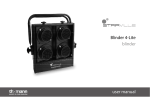
We thank you for choosing the projector BLINDER 2 SINGLE
ROW.
To make the most of this unit and to make it work correctly
in the years, before connecting it to its source and using it,
we suggest you to carefully read this manual.
In this way you will be more familiar with it and its
connections and will be easier to use it.
All the sections of this manual have been studied to make
2 SINGLE ROW.
as easy and complete as possible
the use of the BLINDER
To make the manual more clear and easy to consult, we have used the following symbols and conventions:
!
IMPORTANT
!
very important warnings, to be read with the maximum attention;
important parts of the text that give details and/or explanations on the use of the
BLINDER 2 SINGLE ROW.
practical advices for an efficient use of
the BLINDER 2 SINGLE ROW.
YOUR REFERENCE
Cite the model and the serial number anytime you contact your retailer to ask for information or assistance.
STANDARD PACKAGE
The standard package of the projector BLINDER 2 SINGLE ROW contains:
1) Projector
2 ) M a in s c o n n e c to r
3) U s e r’ s m a nua l
4) Guarantee
ON REQUEST:
* L a m p (c o de 030017)
* B la c k c la m p Ø 5 0 ( c o d e 1 9 4 0 1 9 )
!
IMPORTANT
Make sure that the unit has not been damaged during the transportation.
In case it has happened or in case the unit does not work correctly, immediately contact the Retailer.
If the unit has been directly sent to you , immediately contact the Freight Company.
Only the final receiver (the person or the Company that receive the unit) is in the position to
complain for the above inconveniences.
The safety of the unit is guaranteed only strictly following the instructions, so it is recommended to
accurately preserve them.
User’s manual
product code: 991028
TECHNICAL FEA
TURES
FEATURES
LAMP
PAR 36 DWE 650 W 120 V
VERTICAL
MOVEMENT
+ 9 0 ° /- 4 5 °
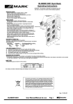
Manual orientation (Fig. 1).
WORKING
POSITION
DIMENSIONS
(W x D x H)
WEIGHT
• Nominal operating voltage: 230 Vac; 50 Hz.
• Rated power supply: 1300 W.
• Nominal current: 5.7 A (230 Vac).
BRACKET
MANUAL
ORIENTATION
KNOB
Any position.
MANUAL
ORIENTATION
KNOB
mm. 430 x 125 x 300 (Fig. 1).
Kg. 3.5
Steel and aluminium.
125
BODY
INSERT FOR CASCADE
MOUNTING
300 mm.
INPUT POWER
fig. 1
mm
.
430 mm
.
WARNINGS
!
!
!
!
!
!
!
!
Do not dismantle and modify the unit.
Always make sure that you are using a safety chain.
Do not install the unit outdoors directly exposed to rain or moisture.
To avoid any inflammable liquids, water or metal objects entering the unit.
To avoid installing the unit close to heat sources. Never to lean the connecting cable on the hot unit.
The unit must be at a minimum distance of 30 cm. from the walls or from any inflammable material and 1 mt.
from lighted objects.
The unit must be placed where it could be easily aerated. To avoid obstructing the in/out air gratings.
Do not directly look at the Lamp when it is on.
ASSEMBLING
!
Before installing the BLINDER 2 SINGLE ROW, make sure that the structure, where to place it, is safe and could
sustain its weight, or, the one of more units cascade mounted.
The BLINDER 2 SINGLE ROW is equipped with a bracket with three holes (diam. 10 mm.) to fix clamps and/or screw
bolts (fig. 1).
To orientate the unit, follow these instructions:
1) Unscrew the knobs placed at the both sides of the projector (fig. 1);
2) Orientate the unit in the preferred position;
3) Screw the above said knobs.
• It is possible to turn the bracket up or down.
!
Once finished make sure that the unit is correctly fixed and stable.
BLINDER 2
SINGLE ROW
CODE 991028
1
CASCADE MOUNTING
The BLINDER 2 SINGLE ROW has been even projected for a cascade mounting (max 4 units).
For a cascade mounting, do as follows:
1) Insert in the middle eye of the bracket a bolt type M8 (fig. 1);
2) Screw the bolt in the insert (fig. 1);
3) Orientate the unit in the preferred position;
4) Fix the knobs and the bolt.
CONNECTION T
O THE POWER SUPPL
Y
TO
SUPPLY
fig. 2
REAR PANEL
POWER SUPPLY INPUT
MANUAL
ORIENTATION
KNOB
!
THREE POLES FEMALE CONNECTOR
FOR THE CONNECTION TO THE MAINS
L
IMPORTANT
The unit must be connected to the earth. The inobservance of
these instructions automatically makes the guarantee expiring.
N
fig. 2/a
L = PHASE (Brown)
N = NEUTRAL (Blue)
= EARTH (Green - Yellow)
Before connecting the unit to the mains, make sure that the working voltage and frequency correspond to the values
indicated on the label (fig. 2).
The BLINDER 2 SINGLE ROW is made to work at a working voltage of 230V 50Hz; 5.7 A.
The unit mains connections are described in fig. 2/a.
fig. 3
LAMP
LAMP
FEMALE CONNECTOR
THREE POLES
BLINDER 2
SINGLE ROW
CODE 991028
2
FITTING AND REPLA
!
IMPORTANT
CING THE LAMPS
In case of replacement of the Lamp or maintenance, never open the unit
unless are passed at least 15 minutes after it went off.
The BLINDER 2 SINGLE ROW is supplied with disassembled iron rings, wires netting and the springs, for mounting
the lamps.
For mounting the lamps, do as follows:
1) Remove the wrappers from the cables.
When mounting and/or replacing the lamps remove the wrapper from two cables per time, to
avoid the cables mixing up. In case it happens, follow the electrical scheme (fig. 3).
2) Connect the two cables terminal to the proper connections of each lamp holder.
3) Place the lamps in their proper room (fig. 4).
4) Lean, on each lamp, one by one, its spring, its wire netting and its iron ring to be fixed with three screws (fig. 4).
To replace the lamps, disassemble all those parts.
Replace the lamps when they reach their maximum average life time.
fig. 4
LAMP
SPRING
WIRE NETTING
IRON RING
LAMP ROOM
SCREWS EYES
MAINTENANCE
!
Before operating any maintenance disconnect the mains.
For operating a correct maintenance of the BLINDER 2 SINGLE ROW follow these instructions:
1) Periodically clean the in/out air grates.
!
Do not absolutely use solvents or abrasive products.
Rev. 11/2005
Working to make its products always more perfect, LED reserves the possibility to make technical changes during the production.
manual are not binding for LED and they could be changed at any time without notice. LED it is not responsible for any inconven
the unit respect to the one for what it has been made.
The technical features and the drawings on this
ience caused by an improper or different use of