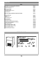
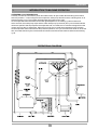
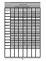
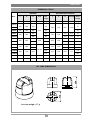
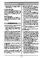
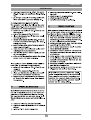
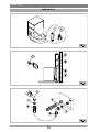
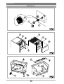
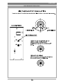
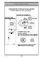
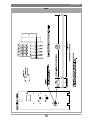
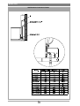
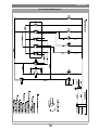
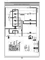
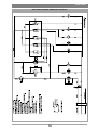
1
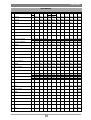
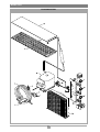
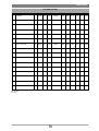
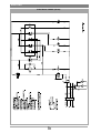
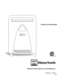
GB
I
KASTEL s.r.l. - Via Fusina, 1/A - 31033
Castelfranco Veneto - Treviso - Italy
AUTOMATIC ICE MAKER
USER MANUAL
All rights reserved. No part of this publication may be reproduced without the written authorisation of the manufacturer
ENGLISH
INDEX
1. INTRODUCTION TO MACHINE OPERATION
Operating cycle description
Operational diagram
Page 3
Page 3
Page 3
2. TECHNICAL DATA
Ice maker technical features
Dimensions table
Ice cube size
Page 4
Page 4
Page 5
Page 5
3. MALFUNCTIONS-CAUSES-ACTIONS TO BE TAKEN
Page 6
4. PARTS SECTION
Casing
Water system
Refrigerating system
Page 8
Page 8
Page 10
Page 12
5. ATTACHMENTS
Instructions booklet
Ice level thermostat adjustment diagram
Evaporator thermostat adjustment diagram
Timer operational diagram
Drain fitting diagram
Electrical diagram KP21 - KP25
Electrical diagram KP28 - KP50
Electrical diagram KP75 - KP130
Electrical diagram KP160
Refrigerating system diagram
Page 14
Page 14
Page 23
Page 24
Page 25
Page 26
Page 27
Page 28
Page 29
Page 30
Page 31
IDENTIFICATION PLATE
2
ENGLISH
1
INTRODUCTION TO MACHINE OPERATION
OPERATING CYCLE DESCRIPTION
Correctly connect the ice maker to power and water mains, fill up the water tank and bring the machine
switch to position “I”. Power will get to the compressor, water pump and fan motors, switching them on to
start the freezing cycle. The nozzles will begin spraying water into the caps.
As the evaporator thermostat bulb reaches the right temperature, the freezing cycle timer starts off.
At the set time, the water pump stops and the water load (to top up the tank) and cycle reversal solenoid
valves are opened. Heat is pumped to the evaporator and, as a result, the ice cubes are dropped from the
copper caps into the ice storage bin. When the bin is full, the ice level thermostat stops ice production.
As the evaporator thermostat reaches the preset temperature, the cycle reversal timer starts off. At the set
time, the water load and cycle reversal solenoid valves are closed and the machine starts a new freezing
cycle.
OPERATIONAL DIAGRAM
3
ENGLISH
TECHNICAL DATA
2
ICE MAKERS - TECHNICAL DETAILS
Mod.
Production
24h
(Kg)
Storage
capacity
(Kg)
Cooling
system
Gas
refrigerant
Cubes in
a cycle
(N°)
Voltage
Power
max.
(W)
KP 21/5
21
5
A
R404A
24
230V~50Hz
420
21
5
W
R404A
24
230V~50Hz
420
22
5
A
R404A
24
230V~50Hz
420
22
5
W
R404A
24
230V~50Hz
420
25
6
A
R404A
24
230V~50Hz
420
25
6
W
R404A
24
230V~50Hz
420
28
7
A
R404A
24
230V~50Hz
530
28
7
W
R404A
24
230V~50Hz
530
30
10
A
R404A
24
230V~50Hz
530
30
10
W
R404A
24
230V~50Hz
530
44
15
A
R404A
36
230V~50Hz
700
44
15
W
R404A
36
230V~50Hz
700
50
26
A
R404A
36
230V~50Hz
800
50
26
W
R404A
36
230V~50Hz
800
75
40
A
R404A
60
230V~50Hz
950
75
40
W
R404A
60
230V~50Hz
950
100
60
A
R404A
60
230V~50Hz
1200
100
60
W
R404A
60
230V~50Hz
1200
130
75
A
R404A
108
230V~50Hz
1350
130
75
W
R404A
108
230V~50Hz
1350
160
75
A
R404A
108
230V~50Hz
1700
160
75
W
R404A
108
230V~50Hz
1700
150
-
A
R404A
108
230V~50Hz
1700
150
-
W
R404A
108
230V~50Hz
1700
300
-
A
R404A
216
230V~50Hz
3500
300
-
W
R404A
216
230V~50Hz
3500
KP 22/5
KP 25/6
KP 28/7
KP 30/10
KP 44/15
KP 50/26
KP 75/40
KP 100/60
KP 130/75
KP 160/75
KP 150 MOD.
KP 300 MOD.
4
ENGLISH
DIMENSION TABLE
MACHINE
Mod.
L
P
H
MACHINE WITH PACKAGE
Foot
Net
L
P
H
Volume
weight
(mm)
(mm)
(mm)
350
450
575
360
450
585
390
465
500
585
740
605
(mm)
(Kg)
Gross
weight
(mm)
(mm)
(mm)
(m3)
430
530
680
0,154
(Kg)
KP21/5
KP22/5
KP25/6
KP28/7
KP30/10
685
795
40
55
710
0,18
42
790
0,2
44
820
0,31
57
930
0,35
61
1050
0,58
80
1150
0,64
96
816
1210
0,9
466
536
576
656
816
676
916
72
1015
87
55÷85
37
38
52
0÷20
915
KP130/75
35
38
685
KP75/40
KP100/60
0÷10
605
KP44/15
KP50/26
34
108
118
840
740
1070
KP150
870
560
730
-
97
925
640
860
0,51
109
KP300
1255
595
860
-
153
1310
640
1015
0,9
170
KP160/75
113
ICE CUBE DIMENSIONS
Ice cube weigh = 17 g
5
123
ENGLISH
3
PROBLEM - REASON - SOLUTION
PROBLEM
REASON
SOLUTION
Switching on the machine, it
No water supply
Check the water system
doesn’t start
No power supply
Check the electrical system
No refrigerant in the ice maker
The condensation cycle is not
correctly effected
Probable gas leak from the cooling
system. Repear the leak
Air cooled system:
-
possible faulty fan motor
-
possible faulty pressure switch
Water cooled system:
- no water in the cooling system
The ice maker effects the cycle
(see “ the safety thermostat
but it doesn’t produce ice
operates”)
Blow-by of the freon from the gas
valve
Blow-by of water throught the
water inlet valve
Low performance of the
compressor
Dirty or faulty water pump
Obstructed suntion filter of the
pump
No water spraid during spaying
period
Change gas valve
Change water inlet valve
Change compressor
First clean water pump, eventually
change it
Check and clean the filter
Faulty or obstructed water inlet
First clean the valve, eventually
valve
change it
Faulty timer: it doesn’t open the
valve
Dirty or obstructed sprayers
Water leak from the bin
The overflow gasket is damaged
The hot gas valve doesn’t open
when operated
Change timer
Check the sparyers and clean
them
Check bin seal
Check and eventually change the
gasket
Check electrical system
Check the valva and eventually
The defrost is not correctly
change it
Faulty evaporator thermostat
Change the thermostat
No water filled up in the bin
Check water flow in the evaporator
The thermostat operates or it is
Check if the bin thermostat has
faulty
operated and eventually change it
Blocked timer
Change the timer
Sheet of ice under the
Faulty evaporator thermostat
Change the evaporator thermostat
evaporator
Faulty or blocked timer
Change the timer
effected
6
ENGLISH
PROBLEM
The ice makers works also when
the bin is full
REASON
Faulty bin thermostat
Bin thermostat not calibrated
No electrical supply
Blocked water valve
The safety thermostat operates
Faulty pressure switch
Scale in the water condenser
Low water level in the bin
Evaporator thermostat not
calibrated
SOLUTION
Check and eventually change the
bin thermostat
Check the thermostat and
eventually calibrate it
Check water system
Check and eventually change the
water valve
Check and eventually change the
pressure switch
Clean the condenser with apposite
anti scale products
See ” no water spraid from
sprayers”
Calibrate thermostat
Check that each jet sprays directly
The ice cubes are not complete
Not standard water jets
without obstacles the center of the
copper cups
The ice maker is not in the correct
Check the feet and place in the
horizontal position
right horizontal position
Small quantity of refrigerant in the
Repear eventula leaks and
cooling system
recharge the refrigerant
See also “decreasing of production”
High ambient temperature and/or
small air circulation
Change place of installation of the
ice maker or change ambient
temperature
Obstracted position of the machine Change place of installation or
(e.g. inside a furniture)
Decreasing of production
Dirty air condenser
High water temperature
Clean the condenser with
compressed air
Check water temperature and
change place of installation
Bin full of water
Check drain pipe of the bin
Small quantity of refrigerant in the
Repear eventula leaks and
cooling system
recharge the refrigerant
The compressor is short-circuited
and/or grounded
The pump is short-circuited and/or
grounded
The circuit breaker operates
permit air circulation
Check and change the compressor
Check and change the pump
The hot gas valve is short-circuited Check and change the hot gas
and/or grounded
valve
The thermostats are grounded
Check and change the thermostat
Other electrical componets are
short-circuited and/or grounded
Circuit breaker differential is faulty
7
Check and change the component
Check and change the component
ENGLISH
4
PARTS SECTION
BODY
8
ENGLISH
BODY
Pos. Description
Note 21/5
22/5
25/6
28/7
30/10 44/15 50/26 75/40 100/60 130/75 160/75
1
Foamed body
K00997 K00997 K00997 K00471 K00470 K00469 K00468 K00466 K00467
K00473
2a
Right angle
K00155 K00155 K00155 K00155 K00155 K00126 K00126 K00052 K00052
K00446
2b
Left angle
K00704 K00704 K00704 K00704 K00704 K00703 K00703 K00702 K00702
K00706
3
Base assembly
K00803 K00803 K00803 K00154 K00154 K00123 K00123 K00550 K00550
K00549
4
Right panel
K00832 K00805 K00995 K01613 K01615 K01618 K01620 K01623 K01625
K01628
5
Left panel
K00831 K00804 K00996 K01614 K01616 K01619 K01621 K01624 K01626
K01629
6
Door
K00828 K00816 K00816 K00241 K00241 K00245 K00245 K00249 K00249
K00456
7
Front panel
K00830 K00811 K00811 K00182 K00165 K00136 K00194 K00063 K00214
K00455
8
Back grid
K00844 K00844 K00844 K00173 K00173 K00195 K00195 K00065 K00065
K00450
9
Back panel
K00810 K00810 K00810 K00178 K00163 K00134 K00191 K00059 K00211
K00448
10
Top assembly
K01369 K01393 K01651 K01658 K01658 K01659 K01659 K01656 K01656
K01657
11
Door support
K00834 K00834 K00834 K00273 K00273 K00274 K00274 K00275 K00275
K00224
12
Thermostat pocket
K00896 K00896 K00896 K00895 K00895 K00043 K00043 K00043 K00043
K00043
13
Foot
K01086 K01086 K01086 K01086 K01086 K01574 K01574 K01341 K01341
K01341
14
Bush
K01148 K01148 K01148 K01148 K01148 K01148 K01148 K01148 K01148
K01148
9
ENGLISH
WATERWORKS
Pos. Description
Note 21/5
22/5
25/6
28/7
30/10 44/15 50/26 75/40 100/60 130/75 160/75
1
Tank
K00800 K00800 K00800 K00149 K00149 K00144 K00144 K00045 K00045 K00300 K00300
2
Tank support
3
Evaporator support
K00817 K00817 K00817 K00151 K00151 K00120 K00120 K00041 K00041 K00320 K00320
4
Flag support assembly
K00826 K00826 K00826 K00225 K00225 K00653 K00653 K00556 K00556 K00227 K00227
5
Flag
K00008 K00008 K00008 K00008 K00008 K00008 K00008 K00008 K00008 K00008 K00008
6
Pawl
K00013 K00013 K00013 K00013 K00013 K00013 K00013 K00013 K00013 K00013 K00013
7
Suction filter
K00012 K00012 K00012 K00012 K00012 K00012 K00012 K00012 K00012 K00012 K00012
8
Suction ring
K00058 K00058 K00058 K00058 K00058 K00058 K00058 K00058 K00058 K00058 K00058
9
Suction pipe
K00823 K00823 K00823 K00185 K00142 K00142 K00198 K00072 K00218 K00218 K00218
10
Pump assembly
/
W
A
/
/
K00152 K00152 K00121 K00121 K00036 K00036 K00439 K00439
K01530 K01530 K01530 K00553 K00553 K00553 K00553 K00553 K00553 K01164 K01164
K01302 K01302
10
ENGLISH
WATERWORKS
Pos. Description
Note 21/5
W
A
25/6
/
/
28/7
30/10 44/15 50/26 75/40 100/60 130/75 160/75
Fan
12
Inlet pipe
K01023 K01023 K01023 K01023 K01023 K01023 K01023 K01023
K01301 K01301
K00824 K00824 K00824 K00184 K00141 K00141 K00197 K00109 K00217 K00217 K00217
13
Inlet ring
K00057 K00057 K00057 K00057 K00057 K00057 K00057 K00057 K00057 K00057 K00057
14
Bar pipe
K00048 K00048 K00048 K00048 K00048 K00048 K00048 K00048 K00048
15
Sprayers bar assembly
K00825 K00825 K00825 K00171 K00171 K00133 K00133 K00047 K00047 K00316 K00316
16
Sprayers
K00220 K00220 K00220 K00220 K00220 K00220 K00220 K00220 K00220 K00220 K00220
17
Plug
K00527 K00527 K00527 K00527 K00527 K00527 K00527 K00527 K00527 K00527 K00527
18
Chute
K00820 K00820 K00820 K00157 K00157 K00124 K00124 K00024 K00024 K00334 K00334
19
Fan motor assembly
20
Overflow assembly
K01083 K01083 K01083
/
/
/
/
K01083 K01083 K01083 K01083
K01380 K01380 K01380
/
/
/
/
/
/
/
/
K01317 K01317 K01317 K01317 K01317 K01317 K01317 K01317 K01317 K01317 K01317
21
Gasket
K01125 K01125 K01125 K01125 K01125 K01125 K01125 K01125 K01125 K01125 K01125
22
Overflow drain
K00006 K00006 K00006 K00006 K00006 K00006 K00006 K00006 K00006 K00006 K00006
23
Gasket
K00536 K00536 K00536 K00536 K00536 K00536 K00536 K00536 K00536 K00536 K00536
24
Ring nut
K01126 K01126 K01126 K01126 K01126 K01126 K01126 K01126 K01126 K01126 K01126
25
Overflow pipe
26
Drain screw nut
K00004 K00004 K00004 K00004 K00004 K00004 K00004 K00004 K00004 K00004 K00004
27
Gasket
K00003 K00003 K00003 K00003 K00003 K00003 K00003 K00003 K00003 K00003 K00003
28
Drain stub pipe
K00039 K00039 K00039 K00039 K00039 K00039 K00039 K00039 K00039 K00039 K00039
29
Drain pipe
K00110 K00110 K00110 K00110 K00110 K00110 K00110 K00110 K00110 K00110 K00110
30
Nipple water outlet
31
Watervalve
32
Hydrohelectrical support
K00578
K00001
K01045
K01212
K00822
33
Cable
K01324 K01324 K01324 K01324 K01324 K01324 K01324 K01324 K01324 K01324 K01324
34
Wye
35
Valve support
36
W
A
/
22/5
11
/
W
A
W
A
/
K00578
K00001
K01045
K01212
K00822
/
/
K00578
K00001
K01045
K01212
K00822
K00578
K00001
K01045
K01212
K00030
/
/
K00541 K00542 K00543 K00540 K00544 K00545 K00545
K00578
K00001
K01045
K01212
K00030
K00578
K00001
K00204
K01213
K00030
K00578
K00001
K00204
K01213
K00030
K00578
K00001
K01322
K01213
K01146
K00578
K00001
K01322
K01213
K01146
K00578
K00001
K01195
K01214
K01146
K00578
K00001
K01046
K01214
K01146
/
/
/
/
/
/
/
W
/
/
/
/
/
/
/
/
/
/
K00330
Nipple
W
/
/
/
/
/
/
/
/
/
/
K01160
37
Pressure valve
W
/
/
/
/
/
/
/
/
/
/
K00497
38
Union tee
/
/
/
/
/
/
/
/
/
K00230 K00230
39
Bar pipe
/
/
/
/
/
/
/
/
/
K00445 K00445
40
Bar pipe
/
/
/
/
/
/
/
/
/
K00444 K00444
41
Pipe
/
/
/
/
/
/
/
/
/
K00311 K00311
W: WATER
A: AIR
11
K00010 K00010 K00010 K00010
ENGLISH
COOLING SYSTEM
12
ENGLISH
COOLING SYSTEM
Pos. Description
Note 21/5
22/5
25/6
28/7
30/10 44/15 50/26 75/40 100/60 130/75 160/75
1
Evaporator
K00145 K00145 K00145
K00145
K00139 K00139 K00138 K00138 K00332 K00332
2
Hot gas valve
K01531 K01531 K01531
K01531
K01531 K01531 K01531 K01531 K01532 K01532
3
Compressor
K00200 K00200 K00200
K01186
K00202 K00085 K00085 K00206 K00475 K00476
4
Water condenser ass.
W
K00278 K00278 K00278
K00112
K00147 K00147 K00017 K00017 K00333 K00333
5
Condenser support
W
K00279 K00279 K00279
K00113
K00146 K00146 K00029 K00029 K00335 K00335
6
Gas filter
K00199 K00199 K00199
K00199
K00199 K00199 K00081 K00081 K00478 K00478
7
Safety thermostat
K00076 K00076 K00076
K00076
K00076 K00076 K00076 K00076 K00076 K00076
8
Electric panel
K00808 K00808 K00808
K00119
K00119 K00119 K00049 K00049 K00049 K00049
9
On-off switch
K00082 K00082 K00082
K00082
K00082 K00082 K00082 K00082 K00082 K00082
10
Timer
K00075 K00075 K00075
K00075
K00075 K00075 K00075 K00075 K00075 K00257
11
Evaporator thermostat
K00080 K00080 K00080
K00080
K00080 K00080 K00080 K00080 K00080 K00080
12
Bin thermostat
K00079 K00079 K00079
K00079
K00079 K00079 K00079 K00079 K00079 K00079
13
Pressure switch
K00077 K00077 K00077
K00077
K00077 K00077 K00077 K00077 K00077 K00077
14
Contactor
15
Evaporator cover
16
Air condenser ass.
W
/
A
/
/
/
/
/
/
/
/
K00500
K00150 K00150 K00150
K00150
K00118 K00118 K00069 K00069 K00226 K00226
K01223 K01223 K01223
K01665
K01225 K01225 K01313 K01314 K01314 K01315
W: WATER
A: AIR
13
ENGLISH
5
ATTACHMENTS
USER MANUAL
14
ENGLISH
USER MANUAL
15
ENGLISH
USER MANUAL
16
ENGLISH
USER MANUAL
17
ENGLISH
USER MANUAL
18
ENGLISH
USER MANUAL
19
ENGLISH
USER MANUAL
20
ENGLISH
USER MANUAL
21
ENGLISH
USER MANUAL
22
ENGLISH
BIN THERMOSTAT REGULATION
23
ENGLISH
EVAPORATOR THERMOSTAT ADJUSTMENT
24
ENGLISH
TIMER
25
ENGLISH
WATER SUPPLY AND ELECTRICAL
26
ENGLISH
ELECTRICAL PANNEL (KP 21)
27
ENGLISH
ELECTRICAL PANNEL (FROM KP28 TO KP50)
28
ENGLISH
ELECTRICAL PANNEL (FROM KP75 TO KP130)
29
ENGLISH
ELECTRICAL PANNEL (KP160)
30
ENGLISH
NOTES
31
Rev.01-Ed.03/05
KASTEL s.r.l.
Via Fusina, 1/A - 31033
Castelfranco Veneto Treviso - Italy
Tel. +39 0423 724061 - Fax +39 0423 743222
E-mail: [email protected]