1
FUJI UG
20-SERIES PROGRAMMABLE OPERATION DISPLAY
USER’S MANUAL
<UG 20 SERIES JEMA-NET Communications>
TYPES: UG03I-J
UG02I-J
FEH358
Preface
UG Series
Thank you very much for purchasing the FUJI UG Series POD (Programmable Operation Display).
This manual describes how to use the UG520/420/320/220 Series POD (hereinafter called UG 20
or POD) of JEMA-NET (JPCN-1)* conforming interface type.
We suggest, however, the reader who has not experienced this software yet go through all the
chapters in order.
This manual is an English version based on the Japanese user’s manual (No. FH358)
[Reference]
In addition to this manual, the following manuals on the UG 20 Series are available. Please ask
your nearest dealer for the appropriate manuals and read them as required.
Name
Manual No.
Contents
UG 20 Series Manual
<Tutorial>
FEH350
Describes how to operate screen editor
(UG00S-3WE) for the UG Series.
UG 20 Series Manual
<Reference>
FEH351
Describes the functions of the UG
Series.
UG520/420/320/220 Series
Manual <Hardware>
FEH352
Describes the UG520/420/320/220 Series
hardware.
20
* JPCN-1 is the field network for programmable controller which is defined in JEM-F3008 standard of the
Japan Electrical Manufacturers’ Association.
Notes
(1) No part of this manual may be reproduced in any form without prior permission of the publisher.
(2) The contents of this manual, including the specifications, are subject to change for improvement without
notice.
(3) This manual was prepared with utmost care. However, if you find any ambiguity, errors, etc., please
contact any of our sales offices that are listed at the end of this manual. In so ding, please tell the
manual number shown on the cover of this manual.
Notes for Your Safety
1. About Printing from UG00S-3WE
1
2
A user-defined external character cannot be printed.
The portion outside the area of 160 120 dots cannot be printed during parts printing (monochrome).
2. About UG00S-3WE Screen Display
1
2
3
If the Windows 95 screen is set to 256-color display, the XOR display of the switches, lamps, and graphic
relays is not normally performed.
Specify High Color (16 bits) to obtain the normal display.
If the Windows 95 screen is set to display 800 600 dots, characters in the dialog window may
sometimes be displayed incorrectly when a large font has been set.
All types of lines are displayed as a solid line in zoom mode (200% or 400%).
Safety Precautions
Before mounting, wiring, operation, maintenance and inspection of the device, be sure to read the operating
instructions carefully to ensure operation. The operating instructions should be furnished to the maintenance
supervisors of final users.
• Here, the safety precaution items are classified into “Warning” and “Caution”
Warning :Incorrect handling of the device may result in death or injury.
Caution :Incorrect handling of the device may result in minor injury or physical damage.
Even some items indicated by “Caution” may also result in a serious accident.
The general safety precautions are described below. Individual precautions are given where necessary, with
the above symbols.
Safety Precautions
Warning
•
Turn OFF the power before mounting, dismounting, wiring, maintaining or checking, otherwise, electric shock,
erratic operation or troubles might occur.
•
Place the emergency stop circuit, interlock circuit or the like for safety outside the PLC. A failure of PLC might
break or cause problems to the machine.
•
Never touch any part of charged circuits as terminals and exposed metal portion while the power is turned ON. It
may result in an electric shock to the operator.
Caution
•
Do not use one found damaged or deformed when unpacked, otherwise, failure or erratic operation might be caused.
•
Do not shock the product by dropping or tipping it over, otherwise, it might be damaged or troubled.
•
Operate (keep) in the environment specified in the operating instructions and manual. High temperature, high
humidity condensation, dust, corrosive gases, oil, organic solvents, excessive vibration or shook might cause electric
shock, fire, erratic operation or failure.
•
Do not place magnetized items near to such things as floppy disks. There is a risk of failure.
•
Insert items such as floppy disks and connectors in the proper direction. There is a risk of failure.
•
Carry out the transfer of screen data during system operation only after checking that everything is safe, as there is a
risk of damage to the set or of an accident owing to operational error.
•
Do not cut off the power during program loading (during access to the hard disk or floppy disk, or during
communication with the POD). There is a risk of erasure of data, product failure, malfunction, mechanical damage or
failure.
•
Use in the software operation environment stipulated in the manual. There is a risk of failure or malfunction.
•
Follow the instructions in the manual regarding the software version. There is a risk of failure or malfunction.
•
Mount and lock the connectors for communication cables securely. There is a risk of failure or malfunction.
•
Do not touch the surface of the floppy disk. There is a risk of failure or malfunction.
•
Carry out regular disk checks. When the hard disk or a floppy disk is used in a damaged state, there is a risk of
failure or malfunction of the data generation system.
•
Follow the regulations of industrial wastes when the device is to be discarded.
Matters Calling for Special Attention
• For "safety precautions", refer to the manuals supplied with the product.
• This POD can communicate with the following PLCs (communication units).
Fuji Electric Co., Ltd.
: FLEX-PC NJ Series communication unit (NJ-JPCN-1)
MICREX-SX Series communication unit (NP1L-JP1)
Mitsubishi Electric Corporation: MELSEC AnA/AnU Series communication unit (AJ71J92-S3)
MELSEC AnS Series communication unit (A1SJ71J92-S3)
Hitachi, Ltd.
: HIDIC S10/2α Series communication unit (LWE580)
HIDIC S10mini Series communication unit (LQE040)
OMRON Corporation
: SYSMAC C200H Series communication unit (C200HW-JRM21)
• To create screen data for UG 20 series, be sure to use Ver 2.00 or newer UG00S-3WE (for Windows).
Ver 1.xx UG00S-3WE, UG00S-3NE (for 98DOS), or UG00S-3DE (for DOS/V) cannot define data for UG
20 Series.
PC selected for UG00S-3W
PLC type setting for UG simulator
Fuji Electric
:
FLEX-PC (JPCN-1)
Fuji Electric
:
FLEX-PC (JPCN-1)
Fuji Electric
:
MICREX-SX (JPCN-1)
Unavailable
Mitsubishi Electric
:
AnA/N/U (JPCN-1)
Mitsubishi Electric
:
AnA/N (JPCN-1)
Hitachi
:
HIDIC-S10 (JPCN-1)
Hitachi
:
HIDIC-S10 (JPCN-1)
OMRON
:
SYSMAC C (JPCN-1)
OMRON
:
SYSMAC C (JPCN-1)
• To use the UG simulator, set as follows:
• Screen data for MICREX-SX cannot be uploaded (reading screen data from POD into editor).
Contents
Chapter 1 General --------------------------------------------------------------- 1-1
Chapter 2 Specifications -------------------------------------------------------- 2-1
Chapter 3 Setting and Wiring a POD ------------------------------------------- 3-1
Chapter 4 Setting for Creating Display Images -------------------------------- 4-1
Chapter 5 Communicating to Fuji Electric’s FLEX-PC ------------------------- 5-1
Chapter 6 Communicating to Fuji Electric’s MICREX-SX ---------------------- 6-1
Chapter 7 Connecting to Mitsubishi’s MELSEC AnA/AnU --------------------- 7-1
Chapter 8 Connecting to Hitachi’s HIDIC S10/2a ----------------------------- 8-1
Chapter 9 Connecting to Omron’s C200H ------------------------------------- 9-1
Chapter10 Error Messages ----------------------------------------------------- 10-1
General
1
General
General
• JEMA-NET PODs are programmable operation displays that transfer data to and from
a master station, such as a PLC, conforming to the specifications of the JEM-F8008
Programmable Controller Field Network Standard (Level 1) as formulated by the
Japan Electrical Manufacturers Association (hereafter called “JPCN-1”).
• As with link unit communications, JEMA-NET PODs do not require any program to
connect to a PLC.
• The compatible class as defined by JPCN-1 is as follows:
TYPE-S511
Isolation type
Wiring type: Two-wire
Baud rate: All rates selected
Unit type: Slave station
1-1
Specification
Specifications
2
Specification
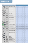
2.1 Compatible Types of PLCs and Communications Modules
Manufacturer
Compatible PLC
Compatible communications module
Fuji Electric
FLEX-PC NJ Series
MICREX-SX Series
NJ-JPCN-1
NP1L-JP1
Mitsubishi
MELSEC AnA/AnN/AnU Series
MELSEC AnS Series
AJ71J92-S3
A1SJ71J92-S3
Hitachi
HIDIC S10/2α Series
HIDIC S10mini Series
LWE580
LQE040
Omron
SYSMAC C200H Series
C200HW-JRM21
2.2 JPCN-1 Communications Specifications
Item
Specification
Maximum number of units
connected
Master station: 1
Slave stations: 31 (PODs are slave stations.)
Station number setting range
01 to 7F
Bus transmission line: Shielded twisted pair cable
Transmission line
Baud rate/
Transmission distance
(The total extension depends on the baud rate.)
125kbps (1000m), 250kbps (800m)
500kbps (480m), 1Mbps (240m)
The transmission distances stated assume the use
of 1.25 mm2 KPEV-SB manufactured by
Furukawa Electric Co., Ltd. and may vary
depending on the characteristics of the cable used.
• Initialization service • Reset service • I/O service
Communications functions
• GET service • PUT service • Data read service
• Data write service (See note 1)
Number of I/O points occupied
Number of message points
Dependent on the POD editor setting.
Maximum transmission length: 250 bytes
Note 1: The PODs do not support any communications functions that are not mentioned
here.
For information about general specifications, please consult the relevant hardware
documentation.
2-1
Specification
2.3 I/O Services and Massaging Services
The PODs use the services mentioned in “2.2 JPCN-1 Communications Specifications,”
as they implement the JPCN-1 communications functions. These services can be
classified into two categories: I/O services and all other services (messaging services).
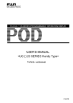
<Concept of I/O services>
An I/O service is a method of communication signals from slaves distributed at remote
locations to a JEMA-NET master module at high speed. Data is updated periodically.
(The timing of data updates varies with the number of connected slave stations, the
number of words occupied by the slave stations, and the baud rate.) To maximize the
rate of transmission between a PLC and PODs, assign their addresses in the I/O
service area. Up to 128 words (2,048 points) can be used per POD (127 words for a
MICREX-SX). With a UG 20 Series POD, an I/O service is enabled by having I/O
memory: JI/J0 is specified with the editor.
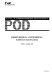
<Concept of messaging services>
Device A
Output
Device B
Output
Input
Device C
Output
Input
Device A
Output
Input
Input
One refresh period
A messaging service is a method of communicating large amounts of data to a JEMANET master module. It allows transmitting data to and from areas other than the I/O
service area. Since data on JEMA-NET is updated once after I/O service has been
refreshed a certain number of times, messaging services take more time to
communicate than I/O services. As a PLC implements messaging service for one
slave at a time, the more devices (such as PODs) that are connected to the PLC for
receiving the message service or the more loaders are connected to the PLC, the longer
the communications time required becomes.
With a UG
20 Series POD, messaging service is enabled by having non-I/O memory
specified as PLC memory with the editor.
Message request
Master
Slave
One cycle
2-2
Message in process
Message completed
Setting and Wiring a POD
Setting and Wiring a POD
3
3.1.1 Interface units
The optional JPCN-1 interface unit is needed for communication with a UG
POD under JPCN-1.
20 Series
Prepare one of the following interface units according to the type of the POD used:
POD type
UG520H-
Interface unit
UG420HUG320H-
UG03I-J
UG220H-
UG02I-J
3.1.2 Setting a station number
Use the rotary switch on the JPCN-1 interface unit to program a POD station number.
UG02I-J
UG03I-J
STN
A
B
SG
STN
H
L
JPCN-1 station No.
setting switch
A
B
SG
H
L
JPCN-1 station No.
setting switch
3-1
Setting a POD
3.1 Setting a POD
Setting and Wiring a POD
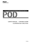
3.1.3 Mounting a JPCN-1 interface unit(UG03I-T)
• Remove the dust-proof seal from the back of the POD before mounting a JPCN-1
interface unit in position with three mounting screws (M3 × 8) included with the unit.
• Wire the communications cable. If a POD is the end-terminal on the cable line, insert
a terminator between signal lines A and B.
• For the UG320, insert the spacer included with the JPCN-1 interface unit into the
upper-left mounting hole and then mount the unit with the included M3 × 15
mounting screw.
I/F unit
Mounting screws (3 positions)
*
L
100240VAC
N
CN1
NC
MJ2
MJ1
CN2
POD
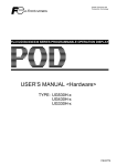
3.1.4 Mounting a JPCN-1 interface unit(UG02I-T)
• Route the insulated cable through
I/F unit
the notch.
• Remove the dust-proof seal from the
back of the POD before mounting a
Notch
JPCN-1 interface unit in position
with three mounting screws (M3 ×
8) included with the unit.
I/F unit
Mounting screws
(3 positions)
DC24V
(+)
(-)
CN1
CN2
MJ2
MJ1
POD
• Connect the insulated
cable with the ground
*
terminal on the POD.
• Wire the communications
cable. If a POD is the
end-terminal on the cable
line, insert a terminator
between signal lines A
and B.
*
Tightening the unit mounting screws
Tighten according to the table below:
3-2
Type of screw
Unit mounting screw
Screw size
M3
Communication terminals
M3.5
Tightening torque (kg.cm)
3 to 5
8 ± 1.5
Setting and Wiring a POD
3.2 Wiring
On JEMA-NET, connect signal lines of the same kind together, such as signal line A,
signal line B, or SG. Make sure that all connections are completed at the same time. If
a POD is the end-terminal on the cable line on JEMA-NET, insert the included
terminator between signal lines A and B.
Remote station on JEMA-NET
3
POD
Signal line A
Signal line B
Signal line B
SG
Wiring
Signal line A
SG
• Complete connections on a two-wire basis as shown above.
• Twist signal lines A and B.
• Cable
On JEMA-NET, use the specified cable type. Data transmission will be unpredictable
with a nonstandard-type cable.
• Cable termination
Terminate cables as shown below.
1
Peeling
2
Solder-less lug connection
Insulating tube
If a cable is directly connected
to a terminal block without
using a solder-less lug, it can
develop a defective contact,
resulting in a communications
error or other fault.
About 40 9
Crossover wiring can be made easier by pairing cables
and having each pair connected to one solder-less lug.
3-3
Setting and Wiring a POD
3.3 External Dimensions
3.3.1 JPCN-1 interface unit external dimensions
UG03I-J
UG02I-J
28.5
167.4
150.5
102.5
STN
A
B
H
SG
L
13.6
14.9
25
98
37.8
3.3.2 External dimensions of PODs equipped with
a JPCN-1 interface unit
UG520
UG420
288
312
92.3
Communications
unit
8
126
240
270
334
UG320
310
Communications
unit
UG220
Communications
unit
173.6
6
66.1
25
220
110
245.2
114.5
215.2
11.5
141.5
16
16
95.8
Communications
unit
85
85
5
50
28.5
182.5
230
*
3-4
UG320 has a 25 mm greater depth.
UG520/420 has the same depth as shown in this figure.
130.8
138.8
165
175
45
Setting for Creating Display Images
Setting for Creating Display
Images
This chapter focuses on the display editor (PC) setting items that are needed to
implement JPCN-1 interface communication.
For additional setting and detailed usage information, see User’s Manual Tutorial
<FEH350> and Reference <FEH351>.
Setting the PLC Type
Create display data for UG
4
20 Series PODs on UG00S-3WE (for
Windows) Ver. 2.00 or higher. Display data for UG 20 Series
PODs is not programmable on UG00S-3WE Ver. xx, UG00S-3NE
(for 98 DOS) and UG00S-3DE (for DOS/V).
4.1 Setting the PLC Type
Choose [Item], [System Setting], and then “Manufacturer and PLC name (JPCN-1)”
from [PLC Type...].
Fuji Electric: FLEX-PC
Mitsubishi: MELSEC AnA/AnN/AnU
Omron: C200H
Hitachi: S10/2α
4-1
Setting for Creating Display Images
4.2 Communications Parameters
Choose [Item], [System Setting], and then [Comm. Parameter...]. Differences from
other methods of communication are mentioned below.
<Main> tab
1
Baud rate
The baud rate setting
must match the PLC
setting.
<I/O word length setting> tab
2
Carry out only I/O communication
If this check box is selected, only the [I/O
memory: JI/JO] is selectable as a memory
specification.
3
Input and output ranges
Set the amounts of data that are communicated by the I/O services. The input range
and the output range can each be set between 1 to 64.
4-2
Communicating to Fuji Electric’s FLEX-PC
Communicating to
Fuji Electric’s FLEX-PC
5.1 NJ-JPCN-1 Settings
NJ
POW
COMM
ALRM
SERR
HERR
1
Station number setting switch
JPCN-1
5
1 2 3 4
OFF
1
Baud rate/transmission distance selector switch
1 2 3 4
OFF
1
2
NJ-JPCN-1 Settings
2
Station number setting switch
If the JPCN-1communications unit is connected to a POD, it is used as a master
module. In this case, set the station number setting switch to 00.
Use the station number setting switch on the JPCN-1 unit to set the station number
for the POD.
2
Baud rate/transmission distance selector switch
The baud rate/transmission distance selector switch has four positions, numbered 1
to 4 from top to bottom. The baud rate/transmission distance is set in a combination
of the ON/OFF states of switch positions 1and 2. Make sure that the baud rate
setting matches the POD loader setting.
Switch positions 3 and 4 are not used; leave them OFF (left side).
1
2
Baud rate/transmission distance
OFF
OFF
OFF
ON
125kbps/1000m
250kbps/800m
ON
ON
OFF
ON
500kbps/480m
1Mbps/240m
5-1
Communicating to Fuji Electric’s FLEX-PC
5.2 Available Memory Locations
The table below lists the memory locations available to items such as switches, lamps
and data displays.
Memory
Bit write
D (data register)
W (link register)
Type
(See note 3)
0
1
Remarks
M (internal relay)
2
If word is specified: WM
L (latch relay)
X (input relay)
3
4
If word is specified: WL
If word is specified: WX
(See note 4)
Y (output relay)
5
R (file register)
6
If word is specified: WY
(See note 4)
Writing from the POD is
TN (timer current value)
7
(See note 1)
CN (counter current value)
T (timer contact)
8
9
(See note 1)
C (counter contact)
S (step relay)
10
11
JI (input relay)
JO (output relay)
56
57
disabled
(See note 4)
(See note 4)
Note 1: The timer and counter current values are designated as TN/CN, respectively, for
convenience. (They are actually T/C.)
Note 2: The programmable range of each memory location depends on the type of the
PLC used and the system architecture. Program the range of each memory
location within a valid range.
Note 3: Use types to address indirect memory locations in a macro.
Note 4: Message if specified with X/Y, and I/O communication if specified with JI/JO.
The memory locations of JI/JO are relative addresses and their actual addresses
in the PLC are determined by the NJ-JPCN-1 module location and the station
number setting on the POD. For more details, see the next section.
5-2
Communicating to Fuji Electric’s FLEX-PC
5.3 Setting the I/O Communications Area
■ Hint on connecting to the FLEX-PC
The NJ-JPCN-1 module V2.05 and later models support reduced mode and standard
mode. (With V2.04 and earlier models, only reduced mode is available.)
The programmable range of JPCN-1 slave station numbers depends on the reduced/
standard mode selection.
Reduced mode
Standard mode
01 to 1F
01 to 7F
Slave station number setting range
To set the station number of a POD between 20 to 7F, run the NJ-JPCN-1 module in
standard mode.
5.3.1 Link register area allocated to the POD
5
Setting the I/O Communications Area
The I/O area (W: link register area) in the PLC that is allocated to the POD is
determined by the NJ-JPCN-1 module location, the JPCN-1 unit station number setting
on the POD, and the communications parameter settings programmed with the POD
editor.
1
NJ-JPCN-1 module location
First, the first two digits (Wxxxx: the lower digit varies with 2 ) of the starting word
address of the allocated link register area are determined by the installation location
of the NJ-JPCN-1 module.
Word address = Mounting slot number × 800 [H]
Power
supply
CPU
module
Slot number
Slot 0
Slot 1
Slot 2
0
1
2
Allocated address range W0000
to 07FF
Starting address: Wn
W0000
Slot 3
3
Slot 4
Slot 5
Slot 6
Slot 7
4
5
6
7
W2000
W0800
W1000
W1800
W2800
W3000
W3800
to 27FF
to 0FFF
to 17FF
to 1FFF
to 2FFF
to 37FF
to 3FFF
W0800
W1000
W1800
W2000
W2800
W3000
W3800
5-3
Communicating to Fuji Electric’s FLEX-PC
2
JPCN-1 station number setting on the POD
Next, the last two digits (Wxxxx) of the starting word address of the allocated link
register area are determined by the JPCN-1 unit station number setting (two digits)
on the POD, which depends on the reduced/standard mode selection of the NJJPCN-1 module.
2
-1 Reduced mode
In reduced mode, 20 [H] words are allocated per slave station. Therefore, the
station number × 20 [H] designates the starting word address of the allocated
link register area.
2
-2 Standard mode
In standard mode, eight [H] words are allocated per slave station. Therefore,
the station number × 8 [H] designates the starting word address of the allocated
link register area.
[Typical setting]
Mount the NJ-JPCN-1
Power
supply
NJ
CPU
Input Input Output
POD editor settings:
NJJPCN-1
module in slot 3 and set the
JPCN-1 unit station number
setting on the POD to 05.
POD: Station number 05
Choose [Item], [System Setting], and
then [Comm. Parameter...]. On the [I/
O word length setting] tab, set both the
input and output ranges to 4.
1
NJ-JPCN-1 module location
Since the NJ-JPCN-1 module is mounted in slot 3:
3 (slots) × 800 [H] = 1800 [H]
Therefore, the starting word address of the allocated link register area is W1800.
5-4
Communicating to Fuji Electric’s FLEX-PC
2
Station number setting on the POD
2 -1 If the NJ-JPCN-1 module is in reduced mode
Since the station number is 05:
5 × 20 [H] = A0 [H]
Add the result of 1 to this value to derive:
1800 [H] + A0 [H] = 10A0 [H]
The starting address of the area allocated to the POD is W18A0. The link
register area allocated to the POD therefore spans from W18A0 to W18A7.
2
-2 If the NJ-JPCN-1 module is in standard mode
Since the station number is 05:
5 × 8 [H] = 28 [H]
Add the result of 1 to this value to derive:
1800 [H] + 28 [H] = 1828 [H]
The starting address of the area allocated to the POD is W1828. The link
register area allocated to the POD therefore spans from W1828 to W182F.
5
Setting the I/O Communications Area
5.3.2 Relationship with memory locations
programmed with the POD editor
The link register area allocated to the POD, when viewed from the PLC standpoint, has
input and output programmed in this order. In [Typical setting] in 5.3.1, the following
relationship exists with the memory locations programmed with the POD editor:
■ If the NJ-JPCN-1 module is in reduced mode
PLC memory locations
F
POD specifications
15
0
W18A0
JI0
1
1
2
2
3
3
4
JO0
5
1
6
2
7
3
0
If JI0-0 is programmed with the POD editor, W18A0 bit 0 (W18A0*0) is associated
with it. If JO1 is programmed with the POD editor, then W18A5 is associated with it.
5-5
Communicating to Fuji Electric’s FLEX-PC
■ If the NJ-JPCN-1 module is in standard mode
PLC memory locations
POD specifications
0
15
0
F
W1828
JI0
9
1
A
2
B
3
C
JO0
D
1
E
2
F
3
If JI0-0 is programmed with the POD editor, W1828 bit 0 (W1828 *0) is associated with
it. If JO1 is programmed with the POD editor, then W182D is associated with it.
5.3.3 Assigned station numbers
The station number that is assigned to the POD is determined by the I/O word length
setting programmed with the POD editor.
Total I/O word length
Assigned station number
2 to 8
Standard mode
1
9 to 16
17 to 24
2
3
25 to 32
33 to 40
4
5
41 to 48
49 to 56
6
7
57 to 64
65 to 72
8
9
73 to 80
81 to 88
10
11
89 to 96
97 to 104
12
13
105 to 112
113 to 120
14
15
121 to 128
16
Reduced mode
1
2
3
4
Though the JEMA-NET module can control up to 31 slave stations by itself, it may
control fewer slave stations depending on the POD setting, as indicated in the table
above.
5-6
Communicating to Fuji Electric’s FLEX-PC
5.4 POD STYPE
There is no need to specify STYPE for the POD when setting parameters on the NJJPCN-1 module. (The POD will run from the defaults.)
When specifying STYPE, program “yes” for all of the following:
DW (write data)
DR (read data)
DO (output data viewed from the master)
DI (input data viewed from the master)
5
POD STYPE
5-7
Communicating to Fuji Electric’s MICREX-SX
Communicating to
Fuji Electric’s MICREX-SX
6.1 NP1L-JP1 Settings
1 Station number setting switch
2 Baud rate/transmission distance selector switch
6
JP1 station number setting switch
If the JP1 communications unit is connected to a POD, it is used as a master module.
In this case, set the station number setting switch to 00.
Use the station number setting switch on the JP1 unit to set the station number for
the POD.
2
Baud rate/transmission distance selector switch
The baud rate/transmission distance selector switch has six switch positions,
numbered 1 to 6 from top to bottom. Set the baud rate to match the POD loader
setting.
Switch positions 1 to 4 are not used; leave them OFF (right side).
ON
1
2
Baud rate/transmission distance
1
2
3
4
5
3
4
5
6
Reserved
6
Baud rate
OFF
OFF
OFF
ON
125kbps/1000m
250kbps/800m
ON
ON
OFF
ON
500kbps/480m
1Mbps/240m
6-1
NP1L-JP1 Settings
1
Communicating to Fuji Electric’s MICREX-SX
6.2 Available Memory Locations
The table below lists the memory locations available for items such as switches, lamps,
and data displays.
Memory
Bit write
Input memory (I)
Output memory (Q)
Type
(See note 3)
0
1
Standard memory (M)
Retained memory (RM)
2
4
System memory (SM)
Global memory (GM)
Input memory (JI)
Output memory (JO)
8
14
56
57
Remarks
(See note 5)
(See note 5)
(See note 5)
(See note 5)
Note 1: The programmable range of each memory location depends on the type of the
PLC used and the system architecture. Program each memory location within a
valid range.
Note 2: Use types to address indirect memory locations in a macro.
Note 3: Specify the CPU number as an extension code when addressing indirect
memory locations in a macro.
Note 4: Message if specified with I/Q; I/O communication if specified with JI/JO. The
memory locations of JI/JO are relative addresses, and the SX station number of
the JPCN-1 module and the station number setting on the POD determine their
actual addresses in the PLC. For more details, see the next section.
The NP1L-JP1 can transmit up to 127 words of data per slave
station through the execution of I/O service.
While up to 128 words (input: 64 words, output: 64 words) can be
programmed as a combined I/O word length with the POD editor,
the I/O word length setting should be held to 127 words or below
due to the limitation above.
6-2
Communicating to Fuji Electric’s MICREX-SX
6.3 Setting the I/O Communications Area
The POD is handled as a JPCN-1 capsule. The PLC addresses are assigned in the order
of input and output according to the JPCN-1 station number setting on the POD by the
rules shown below.
Period
Prefix
SX bus station number
{
Period
JPCN-1 station number
Period
Word number
Bit address
Represented in a range of 00 to 127
(See note).
%IX (bit), %IW (word), %ID (double word)
%QX (bit), %QW (word), %QD (double word)
0 to 15
Note: While the JPCN-1 station number setting on the POD is hexadecimal, this
specification is decimal. The address programmed in hexadecimal should be
handled in decimal.
[Typical setting]
CPU
0
6
I/O
I/O
16-point 16-point
input input
POD
Station number 05
POD editor settings:
Choose [Item], [System Setting],
and then [Comm. Parameter...].
On the [I/O word length setting]
tab, set both the input and output
ranges to 4.
6-3
Setting the I/O Communications Area
Power
supply
JPCN-1 master module: SX station number 1
Communicating to Fuji Electric’s MICREX-SX
Since the SX station number of the JPCN-1 master module is 1, the station number of
the POD is 05, and both input and output word lengths are 4, I/O memory specifications
are programmed with the POD editor as shown below.
PLC memory locations
POD specifications
15
0
15
%IW1.5.0
JI0
1
1
2
2
3
3
%QW1.5.4
JO0
5
1
6
2
7
3
0
If JI0-0 is programmed with the POD editor, %IX1.5.0.0 is associated with it. If JO1 is
programmed with the POD editor, then %QW1.5.5 is associated with it.
6.4 POD STYPE
There is no need to specify STYPE for the POD when setting parameters on the NJJPCN-1 module.
When specifying STYPE, program “yes” for all of the following:
DW (write data)
DR (read data)
DO (output data viewed from the master)
DI (input data viewed from the master)
6-4
Connecting to Mitsubishi’s MELSEC AnA/AnU
Connecting to
Mitsubishi’s MELSEC AnA/AnU
7.1 AJ71J92-S3 Settings
For detailed instructions on AJ71J92-S3 unit settings, see the AJ71J92-S3 User’s
Manual.
The following items require setting in order to connect the POD to Mitsubishi’s
MELSEC AnA/AnU:
(1) Mode setting switch
Set the switch to 0 (online with automatic recovery).
(2) Baud rate selector switch
The switch setting must match the value set with the POD editor.
(3) GET/PUT service setup switch (SW1)
Set the GET/PUT service setting switch to “enabled” to allow POD to use the GET/
PUT services during operation. The switch is disabled by default.
7
AJ71J92-S3 Settings
7-1
Connecting to Mitsubishi’s MELSEC AnA/AnU
7.2 Available Memory Locations
The table below lists the memory locations available to items such as switches, lamps
and data displays.
Memory
D (data register)
W (link register)
Bit write
Type
(See note 2)
0
1
R (file register)
TN (timer current value)
2
3
CN (counter current value)
M (internal relay)
4
6
L (latch relay)
B (link relay)
7
8
X (input relay)
Y (output relay)
9
10
TS (timer contact)
TC (timer coil)
11
12
CS (counter contact)
CC (counter coil)
13
14
JI (input relay)
JO (output relay)
56
57
Remarks
(See note 3)
(See note 3)
(See note 3)
(See note 3)
Note 1: The programmable range of each memory location depends on the type of the
PLC used and the system architecture. Program each memory location within a
valid range.
Note 2: Use types to address indirect memory locations in a macro.
Note 3: Message if specified with X/Y, I/O communication if specified with JI/JO.
7.3 POD STYPE
When specifying STYPE on the AJ71J92-S3 unit, program “yes” for all of the
following:
DW (write data)
DR (read data)
DO (output data viewed from the master)
DI (input data viewed from the master)
Enter the specification by running a PC program. See the sections that follow.
7-2
Connecting to Mitsubishi’s MELSEC AnA/AnU
7.4 Setting the PLC
To connect the POD to an AnA/AnU Series PLC, the PLC would require:
1
A program that is buffered in the AJ71J92-S3 to provide an initialization service
2
A program that launches cyclic communication to provide GET/PUT services
Program 1 involves programming the following POD-specific items:
• Total number of slave stations
• Reset destination station number
• Retry count
• Inter-station delay
• Continued communication specification • Max_int
• Refresh type
• Initialization service information
* The initialization service information is broken down into:
• Initialization service informationA slave station number
• Initialization service informationStype M
• Initialization service informationGET/PUT service specification
7
Setting the PLC
7-3
Connecting to Mitsubishi’s MELSEC AnA/AnU
[Sample program]
A sample program that runs with the AJ71J92-S3 unit inserted in slot 0 in the basic
base and with a POD connected to the first station (station number 1).
M9038
X1F
MOV K1 D100
Total number of slave stations (1)
MOV K5 D101
Retry count (5)
MOV H101 D102
Continued communication specification
(continued I/O data, continued communication request)
MOV K0 D103
Initialization information specification
(addresses 30H to E9H used)
MOV K1 D104
Refresh type specification
(I/O area packed)
TO H0 H0 D100 K5
MOV K3 D105
Inter-station delay (3 ms)
MOV K0 D106
Max_int (infinite)
TO H0 H2E D105 K2
M9038
X17
X18
X1F
MOV H1 D107
Slave station number (station number 1)
MOV H100 D108
Stype M
TO H0 H30 D107 K2
Write initialization service information to station
SET Y17
Start communicating
SET Y18
Start cyclic communication
FROM H0 H300 D200 K64
I/O transfer
X1F
X1F
(example of transferring 64 words from D200
TO H0 H200 D300 K64
7-4
and another 64 words from D300)
Connecting to Hitachi’s HIDIC S10/2α
Connecting to
Hitachi’s HIDIC S10/2α
8.1 LWE580 Settings
For detailed instructions on LWE580 settings, see the LWE580 User’s Manual.
The following items require setting in order to connect the POD to Hitachi’s HIDIC
S10/2α:
(1) Module number setting switch
Set this switch to 00 to let the unit work as a master.
(2) Baud rate selector switch
The switch setting must match the value set with the POD editor.
8
AJ71J92-S3 Settings
8-1
Connecting to Hitachi’s HIDIC S10/2α
8.2 Available Memory Locations
The table below lists the memory locations available to switches, lamps, data displays
and so forth.
Memory
Bit write
FW (work register)
X (input relay)
Type
(See note 2)
0
1
Remarks
If word is specified: XW
Y (output relay)
2
(See note 3, 4)
If word is specified: YW
R (internal relay)
3
(See note 3, 4)
If word is specified: RW
G (global link)
4
(See note 4)
If word is specified: GW
5
(See note 4)
If word is specified: KW
T (on-delay timer [contact])
6
(See note 4)
If word is specified: TW
U (one-shot timer [contact])
C (up-down counter [contact])
7
8
If word is specified: UW
If word is specified: CW
TS (on-delay timer [setting]
TC (on-delay timer [count])
9
10
US (one-shot timer [setting])
UC (one-shot timer [count])
11
12
CS (up-down counter [setting])
CC (up-down counter [count])
13
14
DW (data register)
JI (input relay)
15
56
(See note 3)
JO (output relay)
57
(See note 3)
K (keep relay)
Note 1: The programmable range of each memory location depends on the type of the
PLC used and the system architecture. Program each memory location within a
valid range.
Note 2: Use types to address indirect memory locations in a macro.
Note 3: Message if specified with X/Y; I/O communication if specified with JI/JO.
Note 4: When specifying bits of any of these locations with the POD editor, specify the
bit numbers following the word address.
Example) Specify XW10 bit 15 : X10F
Specify YW80 bit 8 : Y808
Specify GW180 bit 2 : G1802
Specify KW1F0 bit 0 : K1F00
8-2
Connecting to Hitachi’s HIDIC S10/2α
8.3 POD STYPEs
Setting AUTO for STYPE in the LWE580 settings will allow the POD to run
successfully.
When specifying STYPEs program “yes” for all of the following:
DW (write data)
DR (read data)
DO (output data viewed from the master)
DI (input data viewed from the master)
8.4 Setting the PLC
To connect the POD to an S10/2α Series PLC, the PLC requires a JPCN-1 usage
definition. For more details, see the LWE580 User’s Manual.
The items that require setting in order to connect the POD to the Hitachi’s HIDIC S10/
2α are described below, along with sample settings (underlined).
(1) Station number
Set the station number shown on the back of the POD.
(2) Station type
Set “I/O + DR/DW.”
(3) Slot box number
Set the amount of memory that is read into the PLC, or the amount of I/O
communication data, on the [I/O word length setting] tab. To do this, choose [Item],
[System Setting], and then [Comm. Parameter...].
8
POD STYPEs
8-3
Connecting to Omron’s C200H
Connecting to Omron’s C200H
9.1 C200HW-JRM21 Settings
For detailed instruction on C200HW-JRM21 settings, see the C200HW-JRM21 User’s
Manual.
The following items require setting in order to connect the POD to Hitachi’s HIDIC
S10/2α:
(1) Baud rate/error output setting switch
The baud rate switch setting must match the value set with the POD editor.
(2) Station number setting switch
Set this switch to 00 to let the unit work as a master.
9.2 Available Memory Locations
The table below lists the memory locations available to items such as switches, lamps
and data displays.
Memory
DM (data memory)
Bit write
Type
(See note 2)
0
Remarks
CH (I/O relay)
1
HR (latch relay)
LR (link relay)
AR (alarm relay)
T (timer [current value])
2
3
4
5
(See note 4)
C (counter [current value])
JI (input relay)
6
56
(See note 4)
JO (output relay)
57
(See note 4)
(See note 3)
9
C200HW-JRM21 Settings
Note 1: The programmable range of each memory location depends on the type of the
PLC used and the system architecture. Program each memory location within a
valid range.
Note 2: Use types to address indirect memory locations in a macro.
Note 3: LR0 may or may not be available depending on the version of the C200HWJRM21 unit.
Note 4: Message if specified with CH; I/O communication if specified with JI/JO.
9-1
Connecting to Omron’s C200H
9.3 POD STYPE
When specifying STYPE on the C200HW-JRM21 unit, program “yes” for all of the
following:
DW (write data)
DR (read data)
DO (output data viewed from the master)
DI (input data viewed from the master)
9.4 Setting the PLC
To connect the POD to a C200H Series PLC, the PLC requires a definition of JPCN-1
usage. For more details, see the C200HW-JRM21 User’s Manual.
The setting items that are prerequisite to connecting the POD to Omron’s C200HWJRM21 are described below, along with sample settings (underscored).
(1)Master slave/slave identification code
Set master (11H) to connect to a POD.
(2)Initial recognition switch
Set 0.
(3)Number of slave stations registered
(4)Communications monitoring timer
(5)Slave station number
(6)Slave service type (ptype)
Set “0F (H)” (I/O service, READ/WRITE, and PUT/GET service support slave
setting).
(7)IN area starting channel size
Set by the user.
(8)IN data size
Must match the POD editor setting.
(9)OUT area starting channel size
Set by the user.
(10) OUT data size
Must match the POD editor setting.
9-2
Error Messages
Error Messages
This section defines the error messages that may appear during JPCN-1 communication
sessions. For definitions of error messages that may appear during drawing, see User’s
Manual Reference <FEH351>.
■ Error message: Waiting for a response
This message appears in the upper left corner of the screen during a communication
session with the PLC as shown below.
Waiting for a response
SYSTEM
F1
F2
F3
F4
F5
F6
F7
POWER
Error generation conditions
1
Shorter than the PLC interval setting of max_int for JPCN-1 communication (slave
station communications monitoring time).
2
POD editor timeout has expired
(The timeout interval can be programmed on the [Detailed settings] tab, which is
displayed by choosing [Item], [System Setting], and then [Comm. Parameter...].
If a max_int value that is too large (such as infinite) is programmed on the PLC, it
will become impossible to determine the presence or absence of a response from the
PLC, and whether communication is successful or not. Therefore, the error message
will be displayed if these two conditions are established. The error message will be
cleared, however, if a response is received from the PLC within the max_int time
interval.
10
■ Error message: Network I/O access error
can be programmed on the [I/O word length setting] tab,
which is displayed by choosing [Item], [System
Setting], and then [Comm. Parameter...].
You have likely accessed an area out of bounds with a POD macro instructions.
Correct the display data with the POD editor.
10-1
Error Messages
Error occurrence condition: Attempted access outside the I/O ranges
preprogrammed with the POD editor. (The I/O ranges
Fuji Electric Co., Ltd.
ED & C · EDrive Systems Company
Gate City Ohsaki, East Tower
11-2, Osaki 1-chome, Shinagawa-ku, Tokyo, 141-0032, Japan
Phone:
+81-3-5435-7135~8
Fax:
+81-3-5435-7456~9
URL
http://www.fujielectric.co.jp/kiki/
Information in this manual is subject to change without notice.