1
Installation
Chapter 2
How to Install and Wire the Series 942
System Planning
This chapter tells you how to install the Series 942. All mounting and wiring
information is right here. Because Watlow controls are thoroughly tested and
"burned in" before leaving the factory, the Series 942 is ready to install when you
receive it.
But before you begin working, read through this chapter to gain an understanding
of the entire installation. Consider sensor installation carefully. For detailed
information you'll need to look at the noise reduction guidelines in the Appendix of
this manual before making your panel cutout.
Installation Information
The Series 942 mounts in a panel cutout with two brackets, shipped with your
control. These brackets hold the case against the front panel. The Series 942
behind-panel dimensions are 3.6" (90 mm) high by 3.6" (90 mm) wide by 6" (152
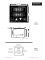
mm) deep. Figure 5 on the next page shows the dimensions of the front panel
bezel. The 942 weighs 2.75 lbs. (1.25 kg) max.
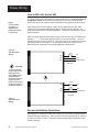
For dimensional and mounting information, including the location of mounting
brackets and size of the front panel cutout, see Figures 5 through 7 on the next
page. Your panel's thickness can be from 0.06" (1.5 mm) to 0.25" (6.3 mm).
NOTE:
Removing the Series
942 chassis from its
case may make
mounting easier.
Installation Procedure
Follow this procedure to mount the Watlow Series 942 Temperature Control:
1. Make a panel cutout per the dimensions in Figure 6.
2. Remove the 942 from its case by turning the front panel screw 90° counterclockwise (CCW). Grip the bezel firmly and pull the control chassis out of the
case.
!
!
WARNING:
The front panel
screw turns 90°
only. Do not apply
excessive force or
turn the screw more
than 90°.
3. Place the case in the cutout you just made.
4. Attach the mounting brackets either to the top and bottom, or to both sides of
the unit.
5. Tighten the mounting brackets securely against your panel.
6. Insert the control chassis into its case and press the bezel to seat it. Turn the
front panel screw 90° clockwise (CW) to lock the control in place. The hardware installation is complete. Proceed to the wiring section from here.
6
WATLOW Series 942 User's Manual
Install and Wire, Chapter 2