1
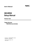
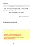
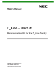
Preliminary Application Note
V850E/IF3, V850E/IG3
32-bit Single-Chip Microcontrollers
Sample Programs for Serial Communication (UARTA)
V850E/IF3:
μPD70F3451
μPD70F3452
V850E/IG3:
μPD70F3453
μPD70F3454
Document No. U18723EJ1V0AN00 (1st edition)
Date Published August 2007 N
2007
Printed in Japan
[MEMO]
2
Preliminary Application Note U18723EJ1V0AN
NOTES FOR CMOS DEVICES
1
VOLTAGE APPLICATION WAVEFORM AT INPUT PIN
Waveform distortion due to input noise or a reflected wave may cause malfunction. If the input of the
CMOS device stays in the area between VIL (MAX) and VIH (MIN) due to noise, etc., the device may
malfunction. Take care to prevent chattering noise from entering the device when the input level is fixed,
and also in the transition period when the input level passes through the area between VIL (MAX) and
VIH (MIN).
2
HANDLING OF UNUSED INPUT PINS
Unconnected CMOS device inputs can be cause of malfunction. If an input pin is unconnected, it is
possible that an internal input level may be generated due to noise, etc., causing malfunction. CMOS
devices behave differently than Bipolar or NMOS devices. Input levels of CMOS devices must be fixed
high or low by using pull-up or pull-down circuitry. Each unused pin should be connected to VDD or GND
via a resistor if there is a possibility that it will be an output pin. All handling related to unused pins must
be judged separately for each device and according to related specifications governing the device.
3
PRECAUTION AGAINST ESD
A strong electric field, when exposed to a MOS device, can cause destruction of the gate oxide and
ultimately degrade the device operation. Steps must be taken to stop generation of static electricity as
much as possible, and quickly dissipate it when it has occurred.
Environmental control must be
adequate. When it is dry, a humidifier should be used. It is recommended to avoid using insulators that
easily build up static electricity. Semiconductor devices must be stored and transported in an anti-static
container, static shielding bag or conductive material. All test and measurement tools including work
benches and floors should be grounded.
The operator should be grounded using a wrist strap.
Semiconductor devices must not be touched with bare hands. Similar precautions need to be taken for
PW boards with mounted semiconductor devices.
4
STATUS BEFORE INITIALIZATION
Power-on does not necessarily define the initial status of a MOS device. Immediately after the power
source is turned ON, devices with reset functions have not yet been initialized. Hence, power-on does
not guarantee output pin levels, I/O settings or contents of registers. A device is not initialized until the
reset signal is received. A reset operation must be executed immediately after power-on for devices
with reset functions.
5
POWER ON/OFF SEQUENCE
In the case of a device that uses different power supplies for the internal operation and external
interface, as a rule, switch on the external power supply after switching on the internal power supply.
When switching the power supply off, as a rule, switch off the external power supply and then the
internal power supply. Use of the reverse power on/off sequences may result in the application of an
overvoltage to the internal elements of the device, causing malfunction and degradation of internal
elements due to the passage of an abnormal current.
The correct power on/off sequence must be judged separately for each device and according to related
specifications governing the device.
6
INPUT OF SIGNAL DURING POWER OFF STATE
Do not input signals or an I/O pull-up power supply while the device is not powered. The current
injection that results from input of such a signal or I/O pull-up power supply may cause malfunction and
the abnormal current that passes in the device at this time may cause degradation of internal elements.
Input of signals during the power off state must be judged separately for each device and according to
related specifications governing the device.
Preliminary Application Note U18723EJ1V0AN
3
Caution: This product uses SuperFlash® technology licensed from Silicon Storage Technology, Inc.
SuperFlash is a registered trademark of Silicon Storage Technology, Inc. in several countries including the
United States and Japan.
• The information contained in this document is being issued in advance of the production cycle for the
product. The parameters for the product may change before final production or NEC Electronics
Corporation, at its own discretion, may withdraw the product prior to its production.
• No part of this document may be copied or reproduced in any form or by any means without the prior written consent
of NEC Electronics. NEC Electronics assumes no responsibility for any errors that may appear in this document.
• NEC Electronics does not assume any liability for infringement of patents, copyrights or other intellectual property
rights of third parties by or arising from the use of NEC Electronics products listed in this document or any other
liability arising from the use of such products. No license, express, implied or otherwise, is granted under any
patents, copyrights or other intellectual property rights of NEC Electronics or others.
• Descriptions of circuits, software and other related information in this document are provided for illustrative purposes
in semiconductor product operation and application examples. The incorporation of these circuits, software and
information in the design of a customer's equipment shall be done under the full responsibility of the customer. NEC
Electronics assumes no responsibility for any losses incurred by customers or third parties arising from the use of
these circuits, software and information.
• While NEC Electronics endeavors to enhance the quality, reliability and safety of NEC Electronics products,
customers agree and acknowledge that the possibility of defects thereof cannot be eliminated entirely. To minimize
risks of damage to property or injury (including death) to persons arising from defects in NEC Electronics products,
customers must incorporate sufficient safety measures in their design, such as redundancy, fire-containment and
anti-failure features.
• NEC Electronics products are classified into the following three quality grades: "Standard", "Special", and "Specific".
The "Specific" quality grade applies only to NEC Electronics products developed based on a customer-designated
"quality assurance program" for a specific application. The recommended applications of an NEC Electronics
product depend on its quality grade, as indicated below. Customers must check the quality grade of each NEC
Electronics products before using it in a particular application.
"Standard": Computers, office equipment, communications equipment, test and measurement equipment, audio and
visual equipment, home electronic appliances, machine tools, personal electronic equipment and
industrial robots.
"Special": Transportation equipment (automobiles, trains, ships, etc.), traffic control systems, anti-disaster
systems, anti-crime systems, safety equipment and medical equipment (not specifically designed for life
support).
"Specific": Aircraft, aerospace equipment, submersible repeaters, nuclear reactor control systems, life support
systems and medical equipment for life support, etc.
The quality grade of NEC Electronics products is "Standard" unless otherwise expressly specified in NEC
Electronics data sheets or data books, etc. If customers wish to use NEC Electronics products in applications
not intended by NEC Electronics, they must contact an NEC Electronics sales representative in advance to
determine NEC Electronics' willingness to support a given application.
(Note)
(1) "NEC Electronics" as used in this statement means NEC Electronics Corporation and also includes its
majority-owned subsidiaries.
(2) "NEC Electronics products" means any product developed or manufactured by or for NEC Electronics (as
defined above).
M5 02. 11-1
4
Preliminary Application Note U18723EJ1V0AN
INTRODUCTION
Cautions 1. This Application Note explains a case where the V850E/IG3 is used as a representative
microcontroller. Use this Application Note for your reference when using the V850E/IF3.
2. Download the program used in this manual from the page of Programming Examples
(http://www.necel.com/micro/en/designsupports/sampleprogram/index.html)
in
the
NEC
Electronics Website (http://www.necel.com/).
3. This sample program is provided for reference purposes only and operations are therefore not
subject to guarantee by NEC Electronics Corporation. When using sample programs, customers
are advised to sufficiently evaluate this product based on their systems, before use.
4. When using sample programs, reference the following startup routine and link directive file and
adjust them if necessary.
• Startup routine:
ig3_start.s
• Link directive file: ig3_link.dir
Target Readers
This Application Note is intended for users who understand the functions of the
V850E/IF3 (μPD70F3451, 70F3452), and V850E/IG3 (μPD70F3453, 70F3454), and
who design application systems that use these microcontrollers.
Purpose
This manual is intended to give users an understanding of the basic functions of the
V850E/IF3 and V850E/IG3, using the application programs.
How to Use This Manual
It is assumed that the reader of this Application Note has general knowledge in the
fields of electrical engineering, logic circuits, and microcontrollers.
For details of hardware functions (especially register functions, setting methods, etc.)
and electrical specifications
→ See the V850E/IF3, V850E/IG3 Hardware User’s Manual.
For details of instruction functions
→ See the V850E1 Architecture User’s Manual.
Conventions
Data significance:
Higher digits on the left and lower digits on the right
Active low representation:
xxx (overscore over pin or signal name)
Memory map address:
Higher addresses on the top and lower addresses on
Note:
Footnote for item marked with Note in the text
Caution:
Information requiring particular attention
Remark:
Supplementary information
the bottom
Numeric representation:
Binary ... xxxx or xxxxB
Decimal ... xxxx
Hexadecimal ... xxxxH
Prefix indicating the power
of 2 (address space,
memory capacity):
K (kilo):
210 = 1,024
M (mega): 220 = 1,0242
G (giga):
30
3
2 = 1,024
Preliminary Application Note U18723EJ1V0AN
5
The function lists are structured as follows.
Hardware name (symbol)
[Function]
Function description
[Function name]
Name of sample function
[Argument(s)]
Type and overview of argument(s)
[Processing content]
Processing content of sample function
[SFR(s) used]
Register name and setting content
[call function(s)]
Name and function of call function(s)
[Variable(s)]
Type, name, and overview of variable(s) used in sample function
[Interrupt(s)]
Name of function
[Interrupt source(s)]
Name
[File name]
Name of corresponding sample program file
[Caution(s)]
Caution(s) upon function usage
Interrupt function
[Function name]
6
Name of interrupt function
[Servicing content]
Servicing content of interrupt function
[SFR(s) used]
Name of interrupt and conditions for occurrence
[call function(s)]
None
[Variable(s)]
Name of variable, function
[File name]
Name of corresponding sample program file
[Caution(s)]
None
Preliminary Application Note U18723EJ1V0AN
Related Documents
The related documents indicated in this publication may include preliminary versions.
However, preliminary versions are not marked as such.
Documents related to V850E/IF3 and V850E/IG3
Document Name
Document No.
V850E1 Architecture User’s Manual
U14559E
V850E/IF3, V850E/IG3 Hardware User’s Manual
U18279E
V850E/IF3, V850E/IG3 Sample Programs for Serial Communication
This manual
(UARTA) Application Note
V850E/IF3, V850E/IG3 Sample Programs for Serial Communication
To be prepared
(UARTB) Application Note
V850E/IF3, V850E/IG3 Sample Programs for Serial Communication (CSIB)
To be prepared
Application Note
2
V850E/IF3, V850E/IG3 Sample Programs for Serial Communication (I C)
To be prepared
Application Note
V850E/IF3, V850E/IG3 Sample Programs for DMA Function Application
To be prepared
Note
V850E/IF3, V850E/IG3 Sample Programs for Timer M Application Note
To be prepared
V850E/IF3, V850E/IG3 Sample Programs for Watchdog Timer Application
To be prepared
Note
V850E/IF3, V850E/IG3 Sample Programs for Timer AA Application Note
To be prepared
V850E/IF3, V850E/IG3 Sample Programs for Timer AB Application Note
To be prepared
V850E/IF3, V850E/IG3 Sample Programs for Timer T Application Note
To be prepared
V850E/IF3, V850E/IG3 Sample Programs for Port Function Application Note
To be prepared
V850E/IF3, V850E/IG3 Sample Programs for Clock Generator Application
To be prepared
Note
V850E/IF3, V850E/IG3 Sample Programs for Standby Function Application
To be prepared
Note
V850E/IF3, V850E/IG3 Sample Programs for Interrupt Function Application
To be prepared
Note
V850E/IF3, V850E/IG3 Sample Programs for A/D Converters 0 and 1
To be prepared
Application Note
V850E/IF3, V850E/IG3 Sample Programs for A/D Converter 2 Application
To be prepared
Note
V850E/IF3, V850E/IG3 Sample Programs for Low-Voltage Detector (LVI)
To be prepared
Function Application Note
V850E/IF3, V850E/IG3 6-Phase PWM Output Control by Timer AB, Timer Q
U18717E
Option, Timer AA, A/D Converters 0 and 1 Application Note
Preliminary Application Note U18723EJ1V0AN
7
CONTENTS
CHAPTER 1 CONTINUOUS TRANSMISSION/RECEPTION .................................................................. 9
8
Preliminary Application Note U18723EJ1V0AN
CHAPTER 1 CONTINUOUS TRANSMISSION/RECEPTION
[Function]
Performs continuous UARTA0 transmission/reception.
[Function name]
uarta_main
[Argument]
None
[Processing content]
Performs transmission/reception for ten times using UARTA0. Stores received data in
buf_rx[], and transmitted data in buf_tx[].
[SFRs used]
UA0REIC: 0x07 (Clears UARTA0 reception error interrupt request signal (INTUA0RE),
releases mask, sets to priority level 7.)
UA0TIC:
0x07 (Clears
UARTA0 transmission
enable
interrupt request signal
(INTUA0T), releases mask, sets to priority level 7.)
UA0RIC:
0x07 (Clears UARTA0 reception end interrupt request signal (INTUA0R),
releases mask, sets to priority level 7.)
[call functions]
uarta_port_set, uarta_set, uarta_start, uarta_send_end, uarta_receive_end, uarta_end
[Variables]
unsigned char buf_tx[]:
Transmit data storing buffer
unsigned char buf_rx[]:
Receive data storing buffer
volatile unsigned char count_tx: Transmission count variable
volatile unsigned char count_rx: Reception count variable
unsigned char count:
Transfer data generating variable
[Interrupts]
uarta_int_send, uarta_int_receive, uarta_error
[Interrupt sources]
INTUA0T, INTUA0R, INTUA0RE,
[File name]
uarta.c
[Caution]
None
[Function name]
uarta_port_set
[Processing content]
Sets alternate-function pin to UARTA0 I/O pin.
[SFRs used]
PFC4:
0x03 (Sets TXDA0 output and RXDA0 input.)
PFCE4: 0x00 (Sets TXDA0 output and RXDA0 input.)
PMC4:
[call function]
None
[Variable]
None
[File name]
uarta.c
[Caution]
None
0x03 (Sets TXDA0 output and RXDA0 input.)
Preliminary Application Note U18723EJ1V0AN
9
CHAPTER 1 CONTINUOUS TRANSMISSION/RECEPTION
[Function name]
uarta_set
[Processing content]
Sets UARTA0 control register. Sets baud rate to 9,600 (bps).
[SFRs used]
UA0CTL1:
0x03 (Sets baud rate to 9,600 (bps).)
UA0CTL2:
0xD0 (Sets baud rate to 9,600 (bps).)
UA0OPT0:
0x14 (Sets to ordinary output of transfer data, ordinary input of transfer
data.)
UA0CTL0:
0x8A (Enables UARTA0 operation, sets to MSB first, and sets odd parity to
output, data character length of 8 bits, and stop bit length of 1 bit.)
[call function]
None
[Variable]
None
[File name]
uarta.c
[Caution]
None
[Function name]
uarta_start
[Processing content]
Enables transmission/reception and writes data to UA0TX register.
[SFRs used]
UA0CTL0.UA0TXE:
1 (Enables transmission operation.)
UA0CTL0.UA0RXE:
1 (Enables reception operation.)
UA0TX
Transmit data register
[call function]
None
[Variables]
unsigned char buf_tx[]:
[File name]
uarta.c
[Caution]
Set UA0RXE and UA0TXE bits to 1 after setting UA0CTL.UA0PWR bit to 1.
[Function name]
uarta_send_end
[Processing content]
Disables transmission operation.
[SFR used]
UA0CTL0.UA0TXE: 0 (Disables transmission operation.)
[call function]
None
[Variable]
None
[File name]
uarta.c
[Caution]
None
10
Transmit data storing buffer
Preliminary Application Note U18723EJ1V0AN
CHAPTER 1 CONTINUOUS TRANSMISSION/RECEPTION
[Function name]
uarta_receive_end
[Processing content]
Disables reception operation.
[SFR used]
UA0CTL0.UA0RXE: 0 (Disables reception operation.)
[call function]
None
[Variable]
None
[File name]
uarta.c
[Caution]
None
[Function name]
uarta_ end
[Processing content]
Disables operation of UARTA0.
[SFR used]
UA0CTL0.UA0PWR: 0 (Disables operation of UARTA0.)
[call function]
None
[Variable]
None
[File name]
uarta.c
[Caution]
None
Interrupt function
[Function name]
uarta_int_send
[Processing content]
Writes transmit data to transmit data register.
Stops transmission operation if number of transmissions and the count value match.
[SFR used]
UA0TX Transmit data register
[call function]
None
[Variables]
unsigned char buf_tx[]:
Transmit data storing buffer
volatile unsigned char count_tx:
Transmission count variable
[File name]
uarta.c
[Caution]
None
Preliminary Application Note U18723EJ1V0AN
11
CHAPTER 1 CONTINUOUS TRANSMISSION/RECEPTION
[Function name]
uarta_int_receive
[Processing content]
Writes receive data to receive data register.
Stops and disables reception operation if number of receptions and the count value
match.
[SFR used]
UA0RX Receive data register
[call function]
None
[Variables]
unsigned char buf_rx[]:
Receive data storing buffer
volatile unsigned char count_rx:
Reception count variable
[File name]
uarta.c
[Caution]
To stop reception operation, set UA0PWR bit to 0 after setting UA0RXE and UA0TXE
bits to 0.
[Function name]
uarta_error
[Processing content]
Clears error flag when reception error occurs.
[SFRs used]
UA0STR.UA0PE:
0 (Clears parity error flag.)
UA0STR.UA0FE:
0 (Clears framing error flag.)
UA0STR.UA0OVE:
0 (Clears overrun error flag.)
[call function]
None
[Variable]
None
[File name]
uarta.c
[Caution]
None
12
Preliminary Application Note U18723EJ1V0AN
CHAPTER 1 CONTINUOUS TRANSMISSION/RECEPTION
Figure 1-1. Continuous Transmission/Reception (1/4)
uarta_main
DI
Disables maskable interrupt request.
count_tx = 0
Initializes transmission count.
count_rx = 0
Initializes reception count.
uarta_port_set
Alternate-function pin setting function
uarta_set
UARTA0 control register setting function
Initializes count for transmission data generated.
count = 0
Yes
count>TX_SIZE
Checks count for transmission data generated.
No
buf_tx[count] = count + 1
Substitutes value in buf_tx[]
Increments count for transmission data generated.
count++
UA0REIC = 0x07
Clears INTUA0RE interrupt request signal,
releases mask, sets to priority level 7.
UA0TIC = 0x07
Clears INTUA0T interrupt request signal,
releases mask, sets to priority level 7.
UA0RIC = 0x07
Clears INTUA0R interrupt request signal,
releases mask, sets to priority level 7.
EI
uarta_start
Enables maskable interrupt request.
UARTA0 operation start function
A
Preliminary Application Note U18723EJ1V0AN
13
CHAPTER 1 CONTINUOUS TRANSMISSION/RECEPTION
Figure 1-1. Continuous Transmission/Reception (2/4)
A
count_rx>=RX_SIZE
No
Checks reception count.
Yes
uarta_receive_end
count_tx>TX_SIZE
UARTA0 reception operation disable function
No
Checks transmission count.
Yes
uarta_send_end
count_rx >= RX_SIZE &&
UARTA0 transmission operation disable function
No
Checks reception and transmission count.
count_tx > TX_SIZE
Yes
uarta_end
14
UARTA0 operation disable function
Preliminary Application Note U18723EJ1V0AN
CHAPTER 1 CONTINUOUS TRANSMISSION/RECEPTION
Figure 1-1. Continuous Transmission/Reception (3/4)
Alternate function pin setting function
UARTA0 control register setting function
uarta_port_set
uarta_set
PFC4 = 0x03
PFCE4 = 0x00
PMC4 = 0x03
Sets alternate-function pin
to TXDA0 output and
RXDA0 input.
UA0CTL1 = 0x03
Sets baud rate to 9,600 bps.
UA0CTL2 = 0xD0
ret
UARTA0 operation start function
UA0OPT0 = 0x14
Outputs transfer data normally.
Inputs transfer data normally.
UA0CTL0 = 0x8A
Enables UARTA0 operation.
Sets transfer direction to MSB first.
Sets parity selection to odd parity.
Sets data length to 8 bits.
Sets stop bit to 1 bit.
uarta_start
UA0TXE = 1
Enables transmission
operation.
UA0RXE = 1
Enables reception
operation.
ret
UARTA0 transmission operation disable function
WAIT
UA0TX = buf_tx[0]
uarta_send_end
Needs to weight
over 2 × fUCLK.
Writes to UA0TX register.
UARTA0 reception operation disable function
UARTA0 operation disable function
uarta_end
uarta_receive_end
ret
Disables transmission operation.
ret
ret
UA0RXE = 0
UA0TXE = 0
UA0PWR = 0
Disables reception operation.
Disables UARTA0 operation.
ret
Preliminary Application Note U18723EJ1V0AN
15
CHAPTER 1 CONTINUOUS TRANSMISSION/RECEPTION
Figure 1-1. Continuous Transmission/Reception (4/4)
INTUA0T interrupt
INTUA0T interrupt function
uarta_int_send
No
count tx<TX SIZE
Checks transmission count.
Yes
UA0TX = buf_fx[count_tx]
Writes to UA0TX register.
count_tx++
Increments transmission count.
Increments
transmission count.
count_tx++
reti
INTUA0RE interrupt
INTUA0R interrupt
INTUA0RE error interrupt function
INTUA0R interrupt function
uarta_error
uarta_int_receive
buf_rx[count_rx] = UA0RX
count_rx++
reti
Stores reception result.
Increments reception count.
UA0PE = 0
Clears parity error flag.
UA0FE = 0
Clears framing error flag.
UA0OVE = 0
reti
16
Preliminary Application Note U18723EJ1V0AN
Clears overrun error flag.
For further information,
please contact:
NEC Electronics Corporation
1753, Shimonumabe, Nakahara-ku,
Kawasaki, Kanagawa 211-8668,
Japan
Tel: 044-435-5111
http://www.necel.com/
[America]
[Europe]
[Asia & Oceania]
NEC Electronics America, Inc.
2880 Scott Blvd.
Santa Clara, CA 95050-2554, U.S.A.
Tel: 408-588-6000
800-366-9782
http://www.am.necel.com/
NEC Electronics (Europe) GmbH
Arcadiastrasse 10
40472 Düsseldorf, Germany
Tel: 0211-65030
http://www.eu.necel.com/
NEC Electronics (China) Co., Ltd
7th Floor, Quantum Plaza, No. 27 ZhiChunLu Haidian
District, Beijing 100083, P.R.China
Tel: 010-8235-1155
http://www.cn.necel.com/
Hanover Office
Podbielskistrasse 166 B
30177 Hannover
Tel: 0 511 33 40 2-0
Munich Office
Werner-Eckert-Strasse 9
81829 München
Tel: 0 89 92 10 03-0
Stuttgart Office
Industriestrasse 3
70565 Stuttgart
Tel: 0 711 99 01 0-0
United Kingdom Branch
Cygnus House, Sunrise Parkway
Linford Wood, Milton Keynes
MK14 6NP, U.K.
Tel: 01908-691-133
Succursale Française
9, rue Paul Dautier, B.P. 52
78142 Velizy-Villacoublay Cédex
France
Tel: 01-3067-5800
Sucursal en España
Juan Esplandiu, 15
28007 Madrid, Spain
Tel: 091-504-2787
Tyskland Filial
Täby Centrum
Entrance S (7th floor)
18322 Täby, Sweden
Tel: 08 638 72 00
Filiale Italiana
Via Fabio Filzi, 25/A
20124 Milano, Italy
Tel: 02-667541
Shanghai Branch
Room 2509-2510, Bank of China Tower,
200 Yincheng Road Central,
Pudong New Area, Shanghai, P.R.China P.C:200120
Tel:021-5888-5400
http://www.cn.necel.com/
Shenzhen Branch
Unit 01, 39/F, Excellence Times Square Building,
No. 4068 Yi Tian Road, Futian District, Shenzhen,
P.R.China P.C:518048
Tel:0755-8282-9800
http://www.cn.necel.com/
NEC Electronics Hong Kong Ltd.
Unit 1601-1613, 16/F., Tower 2, Grand Century Place,
193 Prince Edward Road West, Mongkok, Kowloon, Hong Kong
Tel: 2886-9318
http://www.hk.necel.com/
NEC Electronics Taiwan Ltd.
7F, No. 363 Fu Shing North Road
Taipei, Taiwan, R. O. C.
Tel: 02-8175-9600
http://www.tw.necel.com/
NEC Electronics Singapore Pte. Ltd.
238A Thomson Road,
#12-08 Novena Square,
Singapore 307684
Tel: 6253-8311
http://www.sg.necel.com/
NEC Electronics Korea Ltd.
11F., Samik Lavied’or Bldg., 720-2,
Yeoksam-Dong, Kangnam-Ku,
Seoul, 135-080, Korea
Tel: 02-558-3737
http://www.kr.necel.com/
Branch The Netherlands
Steijgerweg 6
5616 HS Eindhoven
The Netherlands
Tel: 040 265 40 10
G0706