1
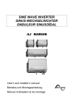
SI STUDER INNOTEC Sine wave inverter SI SERIES User and Installer Manual STUDER INNOTEC SA Rue des Casernes 57 CH-1950 Sion Tel : ++41 (0)27 205 60 80 Fax: ++41 (0)27 205 60 88 [email protected] www.studer-innotec.com User manual SI V3.2.1 E SI STUDER INNOTEC Summary INTRODUCTION ................................................................................................................................ 3 NOTE ..................................................................................................................................................... 3 APPLICATIONS AND PERFORMANCE ........................................................................................ 3 PRODUCT PRESENTATION ............................................................................................................ 3 ASSEMBLY .......................................................................................................................................... 4 LOCATION ........................................................................................................................................... 4 FITTING ............................................................................................................................................... 4 CONNECTION ..................................................................................................................................... 4 USE ........................................................................................................................................................ 4 REMOTE CONTROL .............................................................................................................................. 4 Standby Level (1) ........................................................................................................................... 5 Adjustment procedure .................................................................................................................... 5 CONTROL ............................................................................................................................................ 5 INDICATORS ........................................................................................................................................ 5 Green Run - LED (3)...................................................................................................................... 5 Red Fault - LED (2) ....................................................................................................................... 5 SAFETY ................................................................................................................................................ 5 INTERNAL FUSE ................................................................................................................................ 5 OPTIONS: ............................................................................................................................................. 6 ALARM CONTACT ................................................................................................................................ 6 SOLAR CHARGE CONTROLLER ............................................................................................................. 6 LED “ Charging ” (11) : ............................................................................................................... 6 LED “ Bat. 100% ” (10) : .............................................................................................................. 6 MAINTENANCE.................................................................................................................................. 6 LEGISLATION .................................................................................................................................... 6 LIMITATION OF LIABILITY .......................................................................................................... 6 CE- DECLARATION OF CONFORMITY ....................................................................................... 6 DESCRIPTION AND WIRING DIAGRAM ..................................................................................... 7 WIRING DIAGRAM FOR SI 600 - 800 S (SOLAR CHARGE REGULATOR) ........................... 8 OPTION SI PERFORMANCE 3-PHASED ....................................................................................... 9 WORKING ........................................................................................................................................... 9 1) Working alone ........................................................................................................................... 9 2) Working in a grid ....................................................................................................................... 9 CONNECTING ...................................................................................................................................... 9 COMMISSIONING ................................................................................................................................. 9 TECHNICAL DATA .......................................................................................................................... 10 OPTIONS............................................................................................................................................ 10 User manual SI V3.2.1 E 2 SI STUDER INNOTEC As for the usage of batteries, follow the manufacturer’s instructions. Introduction The SI sine wave inverters have been designed to meet industrial and domestic needs. They satisfy the highest demands of comfort, safety and reliability. Any device designed for the public electrical network of 230V / 50 Hz can be connected to them. The SI inverters are the perfect solution as sources of tension in any place where the public network is not available. Read the connection instructions thoroughly and give them to the technician who is to install the inverter so as to prevent any malfunction. Thus you will have a modern and reliable installation which meets requirements. Should you have any doubt or question, do not hesitate to contact your specialist salesperson who will give you the best advice. Note A deficient assembly could damage the device, cause function failures or potential damage to the users. The working device generates a high tension which might be fatal in case of contact. So, any manipulation of the inverter must be carried out with utmost care. The following points must be strictly observed : The installation of the "SI" can only be performed by a qualified technician. In case of malfunction, only a technician specially designated and trained by STUDER INNOTEC is allowed to repair the device. Warning : Opening the inverters or using them incorrectly will result in the immediate loss of the warranty. No current or tension generating devices (public network, generator, ...) may be connected to the output of the inverter because this could result in its destruction. User manual SI V3.2.1 E Important : After disconnecting the battery, the output tension (230V) may still remain for 30 seconds. The ventilation of the device should never be obstructed. Should the device be installed in an enclosed structure, make sure that ventilation is possible and adequate. The installation and assembly of the device must follow the rules stipulated. This document is an essential part of the inverter and must always be carried with it and be at the disposition of anyone working on the installation. Applications and Performance As well as its modern design and its technical characteristics, the SI inverter is also easy and economical to use in almost all applications. All devices working within the public electrical network (230V - 50Hz) may be used with the inverter (up to its nominal power). The inverter generates a perfectly sinusoid output tension, precisely adjusted by a high technology regulation system. Thus, the output tension is totally independent of the charge and the fluctuation of tension in the battery. All inverters in the SI series are protected against overloading and short circuits. Due to obvious safety reasons, the inverter is not automatically reactivated after a failure (overload, short circuit,…). Product presentation The inverters of the SI series are presented fully equipped, with battery cables, 230V cable and the user's handbook. 3 SI STUDER INNOTEC The tension of the battery should coincide with that mentioned in the technical characteristics of the inverter. Battery connection : This connection should done be very carefully observing the polarity in order not to damage the device. Check that the connections are fixed correctly. Assembly Location The place where the inverter is to be mounted should meet the following requirements : Out of reach of non authorised persons. Use In a dry place with no condensation. After connecting the inverter, make sure the user devices are correctly plugged in and that there is no possible contact between the “ Line OUT ” (6) and a person. No inflammable material in the same room. Not directly on top of the batteries. The working device generates high tensions which could be fatal ! Adequate ventilation. Keep min. 10 cm distance to other object (except mounting side) The inverter can be activated by moving the switch to the “ Auto ” position. The “ on ” indicator -green LED -(3) is illuminated. Warning : The casing of the inverter may reach high temperatures (80 C°) Fitting The inverter has been designed to be used in a vertical position and against the wall. The inverter is fitted using the four external holes ( 5,5 mm). The fitting screws are not supplied with the inverter. Should the inverter be mounted on a flat surface, the maximum continuous power of the inverter may be slightly reduced. Connection Check the switch (4) is in “ OFF ” position. SI xxxxTP model (Twinpower option) : The green LED remains illuminated indicating the uninterrupted presence of 230V in the outlet. The “ Lock ” function deactivates the economical mode. Warning : With the “lock” mode, the no load consumption of the inverter is 15 to 20 times greater ! Remote control The inverter can be controlled remotely with a switch (bi-stable) connected to the “Faston ” (5) connector on the under side of the device. The main switch (4) has priority over the working mode of the device. If the remote switch is close, the inverter is out of use. SI V3.2.1 E 4 First connect the 230V outlet (6) to the user device, so as to prevent any possible accidental contact. Check the tension and polarity of the battery ! User manual SI xxxx model : If no user device is connected, the LED blinks after some seconds, which indicates that the “ standby ” mode has started. If a user device is plugged in, the green LED remains illuminated, indicating the uninterrupted presence of 230V in the outlet. If you wish to deactivate the standby mode, put the switch in “ Lock ” position. The inverter will be then working continuously. SI STUDER INNOTEC Adjustments These values correspond to a no load situation and they are automatically adjusted according to the current of the battery. (Not automatic with Twinpower version) Standby Level (1) The activation of the inverter, when working in automatic mode, is dictated by the detection of a load. With this function, it is possible to adjust the minimum load detected between 0,3 and 20 Watts. This level is factory adjusted to 2 watts and so no further adjustment will probably be needed. The internal temperature and the maximum power are also submitted to control. In the case of prolonged overload or deficient ventilation it is not possible to restart the inverter until it has cooled down. Adjustment procedure Indicators Make sure that no device is connected. Green Run - LED (3) Check for the presence of hidden users such as television, fax, video … which often have a standby mode and remain working even after being turned off ! Illuminated: the inverter is connected. A 230 V tension is present in the outlet. Blinking : (only SI version) The inverter is in “ Autom. ” mode and no voltage is detected by the standby system. Put the switch in “ Autom. ” position. A 230 V tension is intermittently present! Introduce a screw driver N°1 delicately in the hole (1) provided and turn gently until you feel the screw driver insert in the groove of the screw. Turn clockwise (do not force!). until tight without pressing Wait until the green LED blinks. Activate the minimum charge you wish to detect. Turn the screw slowly anti-clockwise without pressing until the inverter activates. (green LED illuminated). Check that the inverter goes back to standby mode a couple of seconds after deactivation of all charges. Warning : In maximum anti-clockwise position the inverter continues to work even if there is no load. Control The tension of the batteries is submitted to control. During their use, the tension must be between the following ranges : 11.4 V and 16 V in the 12 Volt models, 22.8 V and 32 V in the 24 Volt models, 45.6 V and 61 V in the 48 Volt models. Red Fault - LED (2) The inverter is stopped : The tension of the battery is not correct After an overload, overheating or short circuit To restart the inverter after a failure, put the switch (4) in “ OFF ” position for 10 seconds, then connect again. Safety The inverter is internally protected against overloads and short circuits. Should this protection fail, the inverter is equipped with a fuse (fire protection). If the fuse is broken, qualified technicians should control the installation and change the fuse. Internal fuse Fuse 40A 50A 60A 80A 100A 2*100A 2*125A Inverter SI (mod.) 648 624 - 1248 824 – 1448 612 – 2348 - 2360 812 – 1224 – 3548 - 3060 1212 – 1624 – 2324 3324 The use of higher fuse value will not improve the performance of the inverter and will degrade safety protection ! Outside these ranges the inverter is automatically disconnected. User manual SI V3.2.1 E 5 SI STUDER INNOTEC Options: Maintenance Alarm contact The SI inverters do not need any special maintenance. The casing may be cleaned with a damp cloth (not wet). A contact with no potential (0,5A - 60V) is available (12). It warns the user (alarm or control system) when the inverter has been stopped due to a failure or is out of use. It is closed when the inverter is working. In the case of malfunction, the inverter should be sent to the salesperson for control. Legislation Solar charge controller This controller has been designed to charge the batteries with solar installation only. The maximum no load tension of the solar installation should be of 23V for the 12V applications and of 46V for the 24V applications. The max. DC current is 16A and should never be exceeded (20A / 1min.). The mode of adjustment is of the I/U + "floating" type and assures optimal charging conditions for the life of the battery. Charging diagram In all cases the assembly and installation must be done by qualified technicians, observing the national requirements and rules stipulated. You will find complete information about this in the relevant institutions. Limitation of liability STUDER INNOTEC SA cannot control the installation, use and maintenance of the inverter. Thus, we are not responsible for damages, costs or losses resulting from an installation which is not in accordance with the regulations or inappropriate use or maintenance. The customer is always responsible for the use of the inverters STUDER INNOTEC SA. This device has not been designed and is not warranted for use in life support apparatus or any other critical apparatus with potential risks of serious harm to people or to the environment. LED “ Charging ” (11) : It is illuminated when the solar module provides current to charge or maintain the battery. LED “ Bat. 100% ” (10) : It is illuminated when the battery has reached its max. tension (14,4V or 28,8V). It goes off when the tension is above 13V (26V). We do not accept any responsibility for any violation of patent rights or other third person rights resulting from the use of the inverter. STUDER INNOTEC SA reserves the right to modify their products without previous notice. CE- declaration of conformity I declare under that products mentioned on page 11 of this manual are in conformity with the following standards or standardisation documents : EN 61000-6-1, EN 61000-6-3, EN 55014, EN 55022, EN 61000-3-2, Dir. 89/336/EEC, LVD 73/23/EEC Roland Studer Studer Innotec SA Sion : June 19th, 1999 User manual SI V3.2.1 E 6 SI STUDER INNOTEC Description and wiring diagram User manual SI V3.2.1 E 7 SI STUDER INNOTEC Wiring diagram for SI 600 - 800 S (Solar charge regulator) User manual SI V3.2.1 E SI STUDER INNOTEC Option SI performance 3-phased Three SI inverters can be connected together to build a 3-phased grid. They have to be equipped with the PE option. Working Two ways of working are possible with the SI performance : 1) Working alone One SI inverter can be used alone. The inverter works then as a single one, like it is described in this manual. 2) Working in a grid Thanks to the connecting cable, three inverters can be connected together in order to obtain a 3*400V 3-phased grid. User manual Connecting 1) Check that the inverters are in OFF position. 2) First link together the neutral of all 3 devices by taking care that this connecting point is not further than 1 m from each inverter. 3) Link together the battery cables (take care to not reverse the polarity). The 3 inverters have to be connected together to only one battery bank. Commissioning At the time of commissioning it is necessary to operate all the 3 inverters. The inverters work independently from each other and can be loaded in an asymmetrical way. They can work either in stand-by mode or in ON mode (see working description in this manual. SI V3.2.1 E 9 SI STUDER INNOTEC Technical data 612 624 648 812 824 1212 1224 1248 1624 2324 2348 3324 3548 12/24/48 12/24 12/24/48 24 24V/48 24 48 600 800 1200 1600 2300 3300 3500 « Standby » current [mA] Power « ON » no load [W] 25/21/10 2.6 25/21 2.8 25/21/12 4.8 21 5.8 25/17 9 25 13 30 17 Power « ON » no load [W] TWINPOWER system -------- ------- < 0.5 < 0.5 < 0.6 < 0.7 < 0.8 Maximum efficiency [%] 91 92 93 - 95 93 - 95 95 95 95 Length L x 124 (H) x 215 (W) [mm] 276 276 391 391 591 636 791 Weight [kg] 6.9 10.4 13.2 15.2 27 30 38 Model SI Input voltage (Unom) [V] Nominal power [W] Input voltage Dynamic correction of Umin. Output voltage Distortion Dynamic behaviour Frequency Charge detection (standby) Maximum power 15 min Maximum power 3 min Peak power 5s Asymmetric load Cos Protections IP protection index Forced ventilation Min. - Max.: Unom x 0.95 to Unom x 1.33 - 10% at Pnom True sine 230 Vac 3% < 2% (at Pnom) From 0% to 100% load change. Normalization: 0.5 ms 50 Hz 0.01% (Crystal control) Adjustable: 0.3 20 W 1.3 – 1.6 x Pnom / 25°C 1.6 – 2 x Pnom / 25°C 3.5 x Pnom Up to 2 x Pnom 0.1 – 1 Overload/Overheat/Short-circuit/Reverse polarity by internal fuse IP 20 complies with DIN 40050/IP 22 with top cover From 45°C 3°C Overheating protection 75°C 3°C Required battery capacity 5x Pnom/Unom (recommended value) Acoustic level Without ventilation: 10 dB With ventilation: 35 dB EN 61000-6-1, EN 61000-6-3, EN 55014, EN 55022, EN 61000-3-2, Dir. 89/336/EEC, LVD 73/23/EEC EEC conformity Options 3-phased system (per unit) from SI 1200 TwinPower system from SI 1200 Top cover IP 23 Potential free alarm contact (60V/0.5A) for all models Solar charge controller 16A/12-24V for SI 600 and SI 800 Industrial casing in 19’’ rack – 3U x 400 mm from SI 1200 Other specifications on request (Ex: 115V/60Hz). These data are for information only and may change without notice. User manual SI V3.2.1 E SIxxxxPE SIxxxxTP C-IP23 SIxxxxA SIxxxS SIxxxxIND SI in industrial casing 19’’ rack 10