1
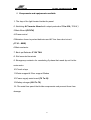
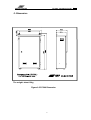
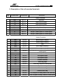
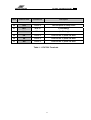
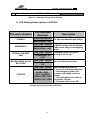
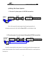
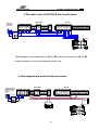
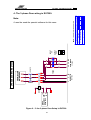
AFP ELAVATOR
EU7500- Installation Guide
EU7500
Emergency Rescue Power
Unit
"User manual"
Version: S2.06
Software: DC3PH180
Manufacture by: AFP ELEVATOR Co.
www.afpelevator.com
0
AFP ELAVATOR
EU7500- Installation Guide
Contents:
Page Number
::::: Overview
Chapter 1:
A) Introduction………………………………………………………………………...……..
3
1- Components and equipments available ………………………….……...
5
2- Dimension……….................................................................................
7
3- Description of the rail-mounted terminals …….……………….…….....…
8
4- How does it work?..................................………………………...............
10
Chapter 2:
C) Important Instructions:
1-Installation guide for AFP EU7500………..……………………….….……….
12
2- LCD Messages Descriptions………………………….……….……………....
13
Chapter 3:
D) How To Wiring The Terminals?
1- Wiring the Power System…………………………………….……….……..…
15
2- Installation Guide for Different Elevator Doors…………….....................
18
Chapter 4:
E) Testing Process:
1- Testing the Operation…………………………………………………………
2- Important Notes………………………………………………………………..
21
22
Chapter 5:
F) Table and Diagrams:
1- EU7500 Terminals connection for different control panels…………….
2- EU7500 Terminals Introduction …………………………………………….
3- Diagrams and Planes………………………………………………….………
1
24
25
26
AFP ELAVATOR
EU7500- Installation Guide
:: Over view
Emergency Rescue Power Unit (EU7500)
Features:
• Automatic function when the power supply is disconnected
• Automatic function in phase loss situations
• Automatic function when the power of the control panel is off
• With automatic charger and batteries function supervision
• High start torque
•
With different timers for the motor suitable function supervision
• Suitable for various types of 3-phase motors with different
powers
• Smart cabin movement distinguishing for reduction in power
usage (low power using)
• Output protection
• LCD display for guiding and errors announcement
• It's designed for main motor with power up to 7.5kw
2
AFP ELAVATOR
EU7500- Installation Guide
Introduction
Chapter1
3
1
AFP ELAVATOR
EU7500- Installation Guide
A) Introductions:
Emergency Rescue Power Unit (Evacuation) , as an automatic
rescuer , is especially designed for the car system movement in power down
situations , as it guides the elevator car to the nearest floor and lets the
passengers leave the cabin , with the BACK-UP batteries energy . So, the
passengers are released from worries. In addition to have all these
preferences, this unit is recommended for use in buildings with extended
access time for emergency rescue.
4
AFP ELAVATOR
EU7500- Installation Guide
1- Components and equipments available
1- The key of the light located inside the panel
2- Switching AC Inverter Board with output protection 70 to 220 ( 700 W )
3-Main Board (DC3PH)
4-Phase control
5-Miniature fuses to protect batteries and AC line from short circuit
(F110 – EMR)
6-Main contactor
7- Back up Batteries 5*12V 7AH
8- Rail mounted terminals
9- Emergency contactor for conducting 3-phase that made by unit to the
main motor
10-Circuit relays
11-Brake magnet & Door magnet Diodes
12-Power supply main board (70 To 24)
13-Battery charger (220 To 70)
14- The metal box panel that holds components and prevent them from
damage
5
AFP ELAVATOR
EU7500- Installation Guide
1
14
13
2
12
3
4
11
10
5
9
6
7
8
Figure 1- EU7500 Components Placement
6
AFP ELAVATOR
EU7500- Installation Guide
2- Dimension:
The weight: about 18kg
Figure 2- EU7500 Dimension
7
AFP ELAVATOR
EU7500- Installation Guide
3- Description of the rail-mounted terminals:
Row
Terminal name
Terminal size
Description
Power Terminals
1
MP
RTP 10
Input Null
2
L1
RTP 10
Input 3-phase power
3
L2
RTP 10
Input 3-phase power
4
L3
RTP 10
Input 3-phase power
5
FL4
RTP 10
Single – phase input before 3-phase main key
6
R
RTP 10
Out put 3-phase power for control panel
7
S
RTP 10
Out put 3-phase power for control panel
8
T
RTP 10
Out put 3-phase power for control panel
Control Terminals
9
BR1
RTP 2.5
Brake magnet output(+)
10
BR2
RTP 2.5
Brake magnet output(-)
11
MP
RTP 2.5
Null
12
DM1
RTP 2.5
Door magnet output(+)
13
DM2
RTP 2.5
Door magnet output(-)
14
FLC
RTP 2.5
Single–phase out put before main–key for
control panel
15
U
RTP 2.5
Fast speed output
16
V
RTP 2.5
Fast speed output
17
W
RTP 2.5
Fast speed output
18
G22
RTP 2.5
Common terminal
19
LEI
RTP 2.5
Level flag input
20
LEF
RTP 2.5
Level flag output to control panel
21
O
RTP 2.5
Open door relay
22
C
RTP 2.5
Close door relay
23
CM
RTP 2.5
Common door relay
24
68 I
RTP 2.5
The end point of safety chain in the hoist way
25
68
RTP 2.5
The end point of safety chain for control panel
8
AFP ELAVATOR
EU7500- Installation Guide
Row
Terminal name
Terminal size
Description
26
G90
RTP 2.5
The first point of safety chain
27
BA1
RTP 10
+ (In Battery)
28
BA2
RTP 10
- (In Battery)
29
UD
RTP 2.5
Used for the 3- phase car door
30
VD
RTP 2.5
Used for the 3- phase car door
31
WD
RTP 2.5
Used for the 3- phase car door
Table1- 1: EU7500 Terminals
9
AFP ELAVATOR
EU7500- Installation Guide
4- How Does It Work?
In phase loss situation, the Emergency Power Unit acts automatically.
After 5 seconds close the cabin door and door magnet; if the safety chain
is O.K, turn the motor to the left to measure the currents of the circuit.
Then , turn the motor to the right to measure the new current , with
comparing the two measured current , it turn the motor to one side that
make the less current.
The cabin moved to desired floor until see the Level flag (LEF) in the
Hoist way. Then the unit command to stop the motor, open the car door, turn
off the cabin light and goes to stand- by situation. This situation goes on
until the main power returns to the normal mode.
The authorized time for the car movement to arrive the floor in
Emergency situation, is 150 seconds.
If it reaches to the floor earlier, the car stopped and the remains time is
for turning on the cabin light. Otherwise, after the time over, cabin stops and
the Emergency unit goes to stand -by mode.
10
AFP ELAVATOR
EU7500- Installation Guide
Important
Instructions
Chapter2
11
2
AFP ELAVATOR
EU7500- Installation Guide
1- Installation Guide to AFP EU7500:
Installation Sequence
1
2
3
4
5
6
7
8
9
10
11
Install the EU7500 panel in suitable place in engine
room
Disconnect the main 3-phase wires R,S,T from
elevator controller inputs
Connect the main 3-phase to L1,L2,L3, MP
terminals of the emergency power unit EU7500
Turn on the main key power; then the Green LED in
phase control in EU7500 should be light.
Turn off the main key power; Connect the EU7500's
R, S, T output terminals to controller panel R, S, T
input terminals.
Descriptions
Near to controller panel.
The Main power key
must be turn off.
Be careful in working.
If there is no green light,
Reverse two phases.
The controller panel main
power will pass from
emergency power panel.
MP terminal is common
between two panels.
Disconnect FLC output wire from main panel and
connect it to emergency power unit EU7500's FL4
input terminal.
Emergency power unit EU7500's FLC output
terminal should be connect to controller panel's FLC
input terminal
The panel power light and
cabin light secure from
emergency power panel.
BR1,BR2,DM1,DM2,UVW,G22,C,CM,68,G90 should
be connect from emergency power panel to controller
panel the same
When the system power
down; if the safety circuit
is OK, the brake power,
the door opening magnet
power and the main
motor 3-phase (low
frequency) secure from
the emergency power
panel.
Level flag ( LEF ) return wire in hoist way should be
disconnect from controller panel and connect to
emergency power panel's LEI terminal
Connect emergency power panel EU7500's LEF
terminal to controller panel LEF terminal
To match the emergency power panel EU7500 with
different safety circuit voltage (specially 24V safety
circuit) and to avoid from each problem 68I terminal
placed
12
AFP ELAVATOR
12
EU7500- Installation Guide
Connect the batteries to the BA1 and BA2 terminals.
Table1-2: Installation Sequence for EU7500
2- LCD Message Descriptions in EU7500:
The work situation
NORMAL
The Displayed
Message
Description
V-BAT=68,VER=XX
Normal mode for AC power supply
, in this case batteries will charge
EMERGENCY UNIT
V-BAT=XX
EMERGENCY
EMERGENCY UNIT
TESTING THE BEST
SIDE
MOVING CABIN IN THE
BEST SIDE
STOPPED
Im=XX Display the batteries voltage and
software version after the system
power down and go to emergency
mode.
Testing the motor current in
moving to left or right
V-BAT=XX Im=XX
TURN RIGHT Or
LEFT
V-BAT=XX Im=XX Selecting the best side to move
the car in the selected way.
RIGHT OR LEFT IS
OK
V-BAT=XX Im=XX Motor stopping because of :
1- CABIN LEVEL
2- FAIL CURRENT
3-MOVETIME OVER
4-SERI STOP OPEN
1. The car is in leveling situations
2. The emergency power unit
current is more than authorize
current
3. The moving time over timer is
active(after 150 sec)
4. The safety chain is not OK.
Table2-2: Description of LCD on EU7500
13
AFP ELAVATOR
EU7500- Installation Guide
How To Wiring
The Terminals?
Chapter 3
14
3
AFP ELAVATOR
EU7500- Installation Guide
a) Wiring The Power System:
1- The main 3- phase power to EU7500 connection:
BR1
BR2
MP
MP
FAN
FTS
DM1
DM2
CL
CPL
+24
G22
G90
66
68
69
O
C
CM
SLF
LEF
V1
W1
U1
V
T
U
S
R
MP
FLC
BA1
BA2
W
G22
LEI
LEF
O
C
CM
68I
68
G90
U
V
BR1
BR2
MP
DM1
DM2
FLC
S
T
L3
R
L2
L1
MP
FL4
W
EC 16
EU 7500
1) 3 PHASE
POWER SUPPLY
TO EU7500
INPUT
R
S
T
MP
3 PHASE BOX
0
1
First of all connect the main power from the main power box to
emergency power unit; after that the Green LED in control phase is on.
2- The main power for control panel through by EU7500 connection:
W1
BR1
BR2
MP
MP
FAN
FTS
DM1
DM2
CL
CPL
+24
G22
G90
66
68
69
O
C
CM
SLF
LEF
V1
W
U1
V
U
T
S
R
MP
FLC
BA2
G22
LEI
LEF
O
C
CM
68I
68
G90
W
U
V
T
BR1
BR2
MP
DM1
DM2
FLC
S
L3
R
L2
L1
MP
BA1
INPUT
R
S
T
MP
EC 16
EU 7500
FL4
2) 3 PHASE POWER
SUPPLY FROM
EU7500 TO MAIN
CONTROLLER
3 PHASE BOX
0
1
It must be connected the main power to the control panel by the emergency unit
power output terminals. Also it must be connected the FLC terminal in control panel for
turning it on.
15
AFP ELAVATOR
EU7500- Installation Guide
3-The main motor to EU7500 & the control panel:
W1
BR1
BR2
MP
MP
FAN
FTS
DM1
DM2
CL
CPL
+24
G22
G90
66
68
69
O
C
CM
SLF
LEF
U1
V
W
U
S
T
R
MP
FLC
BA1
BA2
G22
LEI
LEF
O
C
CM
68I
68
G90
V
W
U
BR1
BR2
MP
DM1
DM2
FLC
S
T
L3
R
L2
L1
MP
FL4
INPUT
R
S
T
MP
V1
EC 16
EU 7500
3) MOTOR
CONECTION
TO EU7500
3 PHASE BOX
0
1
FAST
SLOW
BRAKE
The emergency unit power out put (U, V, W) must be connected to (U, V, W)
output terminals in the control panels one by one.
4- Door magnet and motor brake connection:
BR1
BR2
MP
MP
FAN
FTS
DM1
DM2
CL
CPL
+24
G22
G90
66
68
69
O
C
CM
SLF
LEF
V1
W1
U1
V
U
T
S
R
MP
FLC
BA2
BA1
G22
LEI
LEF
O
C
CM
68I
68
G90
V
W
U
T
BR1
BR2
MP
DM1
DM2
FLC
S
L3
R
L2
MP
L1
INPUT
R
S
T
MP
W
EC 16
EU 7500
FL4
4) DOOR MAGNET,
BRAKE & BATTERY
CONECTION TO
EU7500
3 PHASE BOX
0
1
DOOR
MAGNET
-
+
BATTERY PACK
6*12V 7.2 Ah
16
BRAKE
AFP ELAVATOR
EU7500- Installation Guide
Note:
For connecting the brake output terminal in EU7500 to the brake output
terminal in the control panel; it must be notice to the polarization direction
to prevent from the damaging to the Diode Bridge.
5- The safety chain control terminals:
W1
BR1
BR2
MP
MP
FAN
FTS
DM1
DM2
CL
CPL
+24
G22
G90
66
68
69
O
C
CM
SLF
LEF
U1
V1
V
W
U
S
T
R
MP
FLC
BA1
BA2
W
G22
LEI
LEF
O
C
CM
68I
68
G90
U
V
BR1
BR2
MP
DM1
DM2
FLC
S
T
L3
R
L2
L1
MP
FL4
INPUT
R
S
T
MP
EC 16
EU 7500
5) SERI STOP,
LEVEL & DOOR
CONECTION
3 PHASE BOX
0
1
G22
LEVEL
SENSOR
IN
HOIST
ALL SERI STOP
CONTACTS IN
HOIST WAY
This part is for connecting the level flags, safety chain and door control
terminal between the two units. This is notifying to this connection is just for
the Sematic doors.
17
AFP ELAVATOR
EU7500- Installation Guide
b) Installation Guide to different Elevator Doors:
1- The different Doors Setup in EU7500:
EU7500 is usually designed for Semi Sematic or Full sematic.
So that for the other doors it must be notified as fallows:
• The MP common Null for FERMATOR or BUS Doors must be
the same in both EU7500 & Control panel.
• Also for FERMATOR doors; the open & close control sequence
are the same in both units.
MP
COM
PHASE
OPEN
CLOSE
FERMATOR DOOR
BUS DOOR
Figure 3- the different Doors Setup in EU7500
18
CM
O
C
LEF
LE I
G22
W
V
U
FLC
DM2
MP
DM1
BR2
BR1
T
CM
O
EU 7500 TERMINALS
C
LEF
LE I
W
G22
V
U
DM2
FLC
BR2
MP
DM1
T
BR1
EU 7500 TERMINALS
AFP ELAVATOR
EU7500- Installation Guide
2- three-Phase Car Door:
EU 7500
W1
BR1
BR2
MP
MP
FAN
FTS
DM1
DM2
CL
CPL
UD
VD
WD
+24
G22
G90
66
68
69
O
C
CM
SLF
LEF
U1
V1
U
V
W
FLC
MP
R
S
T
BA1
BA2
G22
LE I
LEF
O
C
CM
68 I
68
G90
UD
VD
WD
V
W
U
BR1
BR2
MP
DM1
DM2
FLC
S
T
L3
R
L2
MP
L1
FL4
EC 16
INPUT
R
S
T
MP
3 PHASE BOX
U
V
W
3 PHASE
0
M
1
DOOR
Note: For these situations it must be notified to our company to provide
the unit by the special Software and Hardware.
Figure 2-5 in chapter 5 could show how to wiring these doors with special
hardware.
19
AFP ELAVATOR
EU7500- Installation Guide
Testing Process
Chapter 4
20
4
AFP ELAVATOR
EU7500- Installation Guide
1- Testing processes:
Row
Follow It
Result
1
Connect the F110 fuse
in EU7500
2
Connect the EMR key
in EU7500
3
F110 fuse or 3-phase
main key in engineroom and FLC key
should be turn off.
The main contactor in EU7500 panel
should be absorbed and the charger board
(68V) turns on (the red & green LED in up
part, right side of the box) then controller
panel EC16 should be turn on.
The Main board in emergency unit turns on.
Batteries voltage displayed, it should be
about 68V. In case of AC power supply,
the contactor and all relays should be
absorbed.
If the car is stocked between two floors
and the safety Chain is OK, first the door
is closed and the DC relay absorbed. After
checking the safety Chain again, the
emergency power system tests the two
sides of movement and selects the side
that is less current. Then it makes the car
to move on this way until reach to the
nearest floor.
Table1-4: TEST SEQUENCE
21
AFP ELAVATOR
EU7500- Installation Guide
2- Important Notes:
Row
FIRST
SECOND
THIRD
FORTH
FIFTH
SIXTH
SEVENTH
EIGHTH
NINTH
TENTH
Notes
For U, V, W connections use the 1.5 mm² wire.
The BA1-BA2 terminals are for the positive & negative Electrodes in
Batteries that placed in EU7500. These must be connected to the panel.
With Connecting the F110 fuse, the main1 contactor absorbs and we will
have three phases in R, S, T output terminals of emergency panel.
The F110 fuse can turn on &off the control panel. In this case the battery
charger is active in Emergency Unit. With cutting off the EMR fuse (20 A)
the emergency unit is turning off too.
Be careful about the installing the brake diode bridge terminals (BR1BR2) and door magnet diode bridge terminals (DM1, DM2) in the right
way. The wrong installation may cause to damage them.
In Emergency mode, if the safety Chain cut off, the motor will stop until
the safety chain is o.k.
The maximum time for emergency unit to move the car and reach the
passenger to the nearest floor is 150sec. the remaining time is showed on
LCD. If the car does not arrive to the floor in this time, the motor will stop.
It must be tested this part with passenger in difference floor carefully to be
ensure of safety act of system.
The permanent cabin light should be 100W at the most. In system power
down, it will turn off and with power up condition; it will be back to the
normal mode.
For recovering the batteries, it must be discharge the batteries once in a
month by the repair-man. It is necessary to change them every two year.
In replacing the panel fuses, please pay attention to their specification on
the panel tray.
Charger board's fuses (4 Amp); Power supply board's fuse (4A);
Inverter board's fuse (15A). Main board's fuse (20A).
Caution: Be aware that not to connect the wire instead of fuse.
Table2-4: IMPORTANT POINTS
Caution:
If the displayed voltage for the batteries on the LCD is 50 volts, it
must be stopped the testing process to give the time the batteries to
charge.
22
AFP ELAVATOR
EU7500- Installation Guide
Tables and
Diagrams
Chapter 5
23
5
AFP ELAVATOR
EU7500- Installation Guide
1- EU7500 terminals connection to EC16 Control Panel:
EU7500
Terminal
FL4
FLC
MP
L1,L2,L3
R,S,T
AFP control
Terminals
…….
FLC
MP
……
R,S,T
U,V,W
U,V,W
BR1
BR2
DM1
DM2
BR1
BR2
DM1
DM2
LEI
……
LEF
LEF
G90
68I
G90
…….
68
68
G22
O
C
G22
O
C
CM
CM
Description
The input phase for EU7500
The output phase for EU7500
Null
Input 3-phase power
Output 3-phase power
Main motor fast speed 3-phase
power
Brake magnet terminals
Door magnet terminals
Level flag input from the hoist
way
Level flag output from EU7500 to
EC16
The first point of the safety chain
The end point of the safety chain
in the Hoist way
The end point of the safety chain
output
Common terminals(0 volt)
Open terminal for door control
Close terminal for door control
Common terminal for door
control
Table1-5: EU7500 terminals connection to EC16 Control Panel
24
AFP ELAVATOR
EU7500- Installation Guide
2- EU7500 Terminals Descriptions:
Row
Terminal Name
Terminal
Size
Description
1
MP
RTP 10
Input Null
2
L1
RTP 10
Input 3-phase power
3
L2
RTP 10
Input 3-phase power
4
L3
RTP 10
Input 3-phase power
5
FL4
RTP 10
Single – phase input before 3-phase main key
6
R
RTP 10
Out put 3-phase power for control panel
7
S
RTP 10
Out put 3-phase power for control panel
8
T
RTP 10
Out put 3-phase power for control panel
9
BR1
RTP 2.5
Brake magnet output (+)
10
BR2
RTP 2.5
Brake magnet output (-)
11
MP
RTP 2.5
Null
12
DM1
RTP 2.5
Door magnet output (+)
13
DM2
RTP 2.5
Door magnet output (-)
14
FLC
RTP 2.5
Single–phase output before main–key for control panel
15
U
RTP 2.5
Fast speed output
16
V
RTP 2.5
Fast speed output
17
W
RTP 2.5
Fast speed output
18
G22
RTP 2.5
Common terminal
19
LEI
RTP 2.5
Level flag input
20
LEF
RTP 2.5
Level flag output to control panel
21
O
RTP 2.5
OPEN DOOR RELAY
22
C
RTP 2.5
CLOSE DOOR RELAY
23
CM
RTP 2.5
COMMON DOOR RELAY
24
68I
RTP 2.5
The end point of safety chain in the hoist way
25
68
RTP 2.5
The end point of safety chain for control panel
26
G90
RTP 2.5
The first point of safety chain
27
BA1
RTP 10
(+)
28
BA2
RTP 10
(-)
29
UD
RTP 2.5
Used for the 3- phase car door
30
VD
RTP 2.5
Used for the 3- phase car door
31
WD
RTP 2.5
Used for the 3- phase car door
Table2-5: EU7500 terminals description
25
26
Figure 1- 5: The EU7500 Internal wiring
R S T
MP 2
FLC 220V
: POWER TERM INAL
: CONTROL TERM INAL
FLC
1
4
2.5 (RED,YELLOW) : BA1,BA2,E70,G70
2.5 (BLACK) : U,V,W
4 (RED,YELLOW,BLUE) : R,S,T
+
44
MAIN2
PHO
PH
-
INPUT
70VDC
43
MP
PH
BR2 MP
MPO
-
MAIN4
OUTPUT
220
VAC
MP
MOTOR BRAKE
MAGNET
BR1
6
MAIN2
5
+
BR
31 32
21
MPO
MAIN1
22
70/220
on/off
NO SWITCH
MAIN1
O1
R1
C1
2
A1
SOFT STARTER
INVERTER 700W
MP
220V
220V
DM1
11
8
PH
-
DOOR
MAGNET
DM2
MP
MP
S
R
T
S
R
G24
G24
OUT
+24
+24
A1
T
DM
G70
IN
_
+
E70
A2
220V MAIN4
MPO
MPO
+
2.5mm
2
220V
S11 MAIN1 A2 MAIN2 10 MAIN3 10
0.75 BLACK : 220V AC&DC
0.75 BLUE : M P
0.75 RED :+24
0.75 YELLOW : G24
0.75 GREEN : G90,G22,68,C,CM ,LEF
3
MAIN4
MP
44 43
31 32
10
MAIN1
T
S
R
LG GMC32
MP
L3 MP
PHASE
L2 CONTROL
MAIN
TO ELEVATOR
POWER CONTROL
PANEL
M A IN1
PHASE
CONTROL
24
_
+
_
U
V
W
+
INPUT
R1
(AUX)
R4
(DOOR)
R3
(BRAKE & DM )
R2
(TO INVERTER)
4
LEI
1
O4
C3
C4
O3
CM3
O2
3
C
CM
1
3 5
7 8
9
11
68I 68 G90
6
U V W
BA1
Code :
Company :
Dev ice :
G07P02V09
AFP ELEVATOR
EU 7500
09
Designed by
Drowned by
Cheched by
Approv ed by
Field
Re v.
BA2
_
G70
B
KARIMI
NASSIRI
ELECTRIC
NASSIRI
KARIMI
Size
1385/04/10
1385/04/10
1385/04/10
1385/04/10
Date
BATTERY SUPPLY
5*12V 7.2 A
+
LG GMC12
EU7500 NORMAL CIRCUIT V.6 MAINBOARD
LEVEL TERM INAL OF AFP
CONTROLER
LEF G22 O
4
G70
20 A
EMR
OUTPUT
G70
-
+70V
E70 E70
OUTPUT VOLTAGE
SETTING : 68.5V
FOR 5 BATTERY
SWITCHING
CHARGER
C1 TO
O1 INVERTER
PHO
C2
COM
(SERI STOP) IN1
(LEVEL) IN2
DC3PH_V6
MAINBOARD
MP
220 V
3- EU7500 Internal Wiring:
FL4 MP L1 L2 L3
MP
2T 1
1L 1
4T 2
3L 2
6T 3
5L 3
O U T:3 P H A S E
L1
6A
M A IN3
VERSION G07P02V09
1L 1
2T 1
F11
3L 2
PHASE
CONTROL
16
15
M A IN4
5L 3
6T 3
4T 2
IN :70V D C
M AIN 2
AFP ELAVATOR
EU7500- Installation Guide
10
27
MP
DC3PH
CM3
MAINBOARD R3
OF EU 7500
O3
2
DOOR 220V
PHO
MAIN4
Figure 2 - 5: the 3-phase Door Setup in EU7500
8
TRANS
I2
v
O3
Y W Z
y w z
I3
3 PHASE
VD WD
O2
U X V
u x
UD
O1
I1
DOOR MOTOR
W
5 9
11
FAST COIL
V
4 7
6
LG GMC12
MAIN MOTOR
U
3
1
1L 1
2T 1
W
3L 2
4T 2
V
5L3
6T 3
U
FROM DC3PH
MAINBOARD
3 PHASE DOOR FOR EU7500
DELTA
x
w
y
u
z
v
OUTPUT
380
INPUT
60
It must be used the special software for this case.
USE SPECIAL SOFTWARE FOR 3PHASE DOOR
Note:
Code :
Company :
Dev ice :
G07P04V05
AFP ELEVATOR
EU 7500
02
Designed by
Drowned by
Cheched by
Approv ed by
Field
Rev.
B
KARIMI
NASSIRI
ELECTRIC
KARIMI
KARIMI
Size
1385/03/25
1384/03/25
1385/03/25
Date
3PHASE DOOR FOR EU 7500 3PH TRANS 60/380
NOTE:
AFP ELAVATOR
EU7500- Installation Guide
4- The 3-phase Door wiring in EU7500:
AFP ELAVATOR
EU7500- Installation Guide
Note:
28