1
PLC-2450
REVISION 1.3
POWER SUPPLY/BATTERY CHARGER
USER MANUAL
Prologic Controls Ltd. 2318-18th Avenue N.E. Calgary, Alberta T2E 8R1
Ph: 403-250-2909 Fax: 403-291-4949
1
SAFETY FIRST
CAUTION! Please read before using your power supply
All electrical installations must meet local and national wiring codes and should be performed
by qualified electricians.
Power supply disassembly or repair should be carried out by qualified technicians. Incorrect
reassembly or repairs may cause electric shocks or fires, which could result in personal injury
and/or property damage.
Ensure the use of properly rated fuses, as shown in the specifications and drawings.
Do not expose the power supply to rain, snow, or water spray.
Standalone Unit Safety
All PLC2450 Power systems use at least one PLC2450 standalone unit as the basic building
block. For systems consisting of more than the standalone unit shown below in fig. 1, this
manual is meant to be used in conjunction with system-specific drawings.
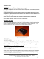
Fig. 1: PLC2450 Standalone Unit
120 Volt AC Power
Standalone unit AC power should be 3 wire, single phase, 120VAC, 60 HZ, 20 amp power,
and should use #12 AWG or larger wire, with proper power, neutral, and ground connections.
Make sure AC Power is switched off before connecting any device to the power supply.
27.6 V DC Output connections (Battery and Load)
All DC connections for each standalone unit need to be sized to carry 50 amps, which is a
minimum #2 AWG wire size.
Always ensure that the positive and negative output connections are secure and the screws
are tightened properly. Loose connections can result in excessive voltage drops and may
cause overheated wires and melted insulation.
Prologic Controls Ltd. 2318-18th Avenue N.E. Calgary, Alberta T2E 8R1
Ph: 403-250-2909 Fax: 403-291-4949
2
INDEX
COVER - - - - - - - - - - - - - - - - - - - - - - - - - - - - - - - - - - - - - - - - - - - - - - - - 1
SAFETY FIRST - - - - - - - - - - - - - - - - - - - - - - - - - - - - - - - - - - - - - - - - - - 2
INDEX - - - - - - - - - - - - - - - - - - - - - - - - - - - - - - - - - - - - - - - - - - - - - - - - - 3
OPERATION - - - - - - - - - - - - - - - - - - - - - - - - - - - - - - - - - - - - - - - - - - - - 4
Standalone Unit Features - - - - - - - - - - - - - - - - - - - - - - - - - - - - - - - - - 4
DC Power Supply
DC Uninterruptable Power
Cooling Fan Operation
25 pin D-Connector Features
Multiple Unit Features - - - - - - - - - - - - - - - - - - - - - - - - - - - - - - - - - - - 6
48 VDC Systems
100 Amp Systems
Interface Option - - - - - - - - - - - - - - - - - - - - - - - - - - - - - - - - - - - - - - - 6
Specifications – Standalone Unit - - - - - - - - - - - - - - - - - - - - - - - - - - - - 9
Specifications – Interface Option - - - - - - - - - - - - - - - - - - - - - - - - - - - - 9
TROUBLESHOOTING - - - - - - - - - - - - - - - - - - - - - - - - - - - - - - - - - - - - - 10
Troubleshooting - - - - - - - - - - - - - - - - - - - - - - - - - - - - - - - - - - - - - - 10
Limiting Electromagnetic Interference (EMI) - - - - - - - - - - - - - - - - - - - - 11
LIMITED WARRANTY - - - - - - - - - - - - - - - - - - - - - - - - - - - - - - - - - - - - - 13
Prologic Controls Ltd. 2318-18th Avenue N.E. Calgary, Alberta T2E 8R1
Ph: 403-250-2909 Fax: 403-291-4949
3
OPERATION
Standalone Unit Features
DC Power Supply
The power supply converts 120 V, 60 HZ. AC power into tightly regulated 27.6 V DC, +/- 1%
delivering up to a maximum of 50 A continuous, (up to 55 A surge) with 5 base level PCB
modules.
The unit is designed using advanced switch mode technology and load share circuitry for high
reliability, high efficiency, and minimum size and weight. It is modular in construction consisting
of 5 Base Level PCB modules (referred to as PSM “Power Supply Modules”) that are
connected for parallel operation with true current sharing. Each module is a standalone power
supply which delivers up to a maximum of 10 A continuous (11 A surge). By equalizing the
output currents, uniform thermal stress of the individual modules is also ensured which has
utmost importance for long term reliability for electronic components. The operating principle of
the load share mechanism is to measure the output current of each individual module and to
be able to modify the output voltage of the units until all the participating modules deliver equal
output currents. Each module is required to be inter-connected with each other to a common
“Share Bus” through a pair of parallel pins marked “JUMP 1” and jumper wires. Typically, the
output currents for the paralleled units will be within 10% of each other at full output current.
DC Uninterruptable Power
With the addition of batteries to terminals B1 and B2, the standalone unit becomes an
uninterruptable power supply.
Fig. 2: DC Schematic Showing Internal Battery and Load Connections
Prologic Controls Ltd. 2318-18th Avenue N.E. Calgary, Alberta T2E 8R1
Ph: 403-250-2909 Fax: 403-291-4949
4
The batteries are always internally connected to the load, so on a loss of AC power there is no
mechanical switching which takes place. As the AC power fails, the output voltage of the PSM
drops slightly until it matches the battery voltage, at which time the batteries take over the role
of providing current to the load. The system can be expanded to provide any amount of backup
power. The only practical consideration is that for each hour of backup power provided at full
load (50 amps), 5 to 6 hours of recharging time will be needed.
Note that in this configuration, battery charging can consume 8 amps of the 50 amps
generated by the power supply leaving only 42 amps available for the load. Keep this in mind
when sizing the system.
Cooling Fan Operation
Heat generated due to internal power dissipation is removed by forced cooling through two
high power D.C. fans mounted at the back of the unit. These fans force outside air into the unit,
where it travels across the internal components and then out through the vent holes provided
on the two sides of the unit. It is extremely important that the suction side fanopennings and
the discharge side vent holes are not blocked.
A warning circuit monitors the operational condition of the fans. In case of fan failure a buzzer
will sound and in systems where the Interface option is implemented, the ‘TEMP-FAIL’ reading
will be shown on the Status Screen. The unit should be switched off immediately and the
defective fan should be replaced. Never load the unit when there is a TEMP-FAIL status or the
buzzer is on.
25 pin D-Connector Features
There is a 25 pin D-sub connector for remote monitoring and indication. If the Interface Option
was chosen, this connector is not available for other uses. Pin connections are given below:
Fig. 3: 25 Pin D-Connector Pinout
Prologic Controls Ltd. 2318-18th Avenue N.E. Calgary, Alberta T2E 8R1
Ph: 403-250-2909 Fax: 403-291-4949
5
Multiple Unit Features
48 VDC Systems
The output of two standalone systems can be wired in series to achieve a 48 volt (54.6 VDC
+/- 1%) power supply. This is a common configuration used in wireless and other
communication systems.
100 Amp Systems
The output of two standalone systems can be wired in parallel to achieve a 24 volt (27.6 VDC
+/- 1%) 100 Amp power supply. Additional supplies can be paralleled to achieve 150 Amp, 200
Amp, 250 Amp supplies, and so forth.
Interface Option
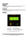
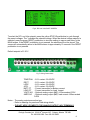
Fig 4: Interface Unit with MAIN SCREEN shown
DC LD VOLTS
CHG LD AMPS
BAT CH AMPS
BAT LD AMPS
- the voltage applied to the load
- the current the load is using
- the current used to charge the batteries
- the current from the batteries to the load
The * is the heartbeat indicating program is running
Prologic Controls Ltd. 2318-18th Avenue N.E. Calgary, Alberta T2E 8R1
Ph: 403-250-2909 Fax: 403-291-4949
6
STATUS pushbutton will move to the alarm and relay status screen (will move to the DC Low
Volts SetPT screen from the status screen)
RESET pushbutton will reset alarms when fault condition clears when pushed from the main
screen or the status screen
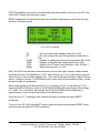
Fig 5: STATUS SCREEN
AC
DC
CHRG
TEMP
PCB
Relays
– AC circuit feeding the charger either OK or FAIL
– DC volts is above the Low Voltage Setpoint either OK or
FAIL
– Charger is running and carrying the load either OK or FAIL
– Charger cooling fans are running either OK or FAIL
– Status of the 5 Power Control Modules 1=OK, 0=FAULT
– Alarm relays are on=1 or off=0
Note: The PCB’s are internally interconnected to monitor the output voltage of each module,
and share the load. The deviation is .5 VDC, and is factory set. It is not uncommon to see the
status of one or more modules change from 1 to 0 under small load conditions. Each PCB can
deliver 10 amps of current. If a PCB remains at 0 under near full load conditions (50A), contact
technical support for assistance.
Alarm relays are set to be either latching (LT-Y) as shown in Fig 5, or non-latching (LT-N).
Pressing the STATUS button while on the STATUS SCREEN will cycle between the settings
LT-Y and LT-N. If no buttons are pressed, the STATUS SCREEN will be displayed for
approximately 15 seconds and then return to the MAIN screen.
When set up in LT-Y (latching) mode, alarms are reset by pushing the green RESET
pushbutton.
To move to the DC LOW Volts SetPT screen, press and hold down the green RESET button
and then press the yellow STATUS pushbutton.
Prologic Controls Ltd. 2318-18th Avenue N.E. Calgary, Alberta T2E 8R1
Ph: 403-250-2909 Fax: 403-291-4949
7
Fig 6: DC Low Volts SetPT SCREEN
To select the DC Low Volts setpoint, press the yellow STATUS pushbutton to cycle through
the preset voltages. The * indicates the selected voltage. When the desired voltage setpoint is
selected, press the green RESET pushbutton to store the setting to eeprom and return to the
MAIN screen. If the RESET pushbutton is not pressed, the selection will not be stored. This
screen will automatically return to the MAIN screen in approximately 10 seconds if the RESET
pushbutton is not pressed.
Default setpoint is 21.50 V
Fig 7: Wiring Connections
TEMP/FAN
RECT
LODC
ACFL
BATT CT
LOAD CT
VOLTS AO
AMPS AO
- N.O. contact .5A 24VDC
- N.O. contact .5A 24VDC
- N.O. contact .5A 24VDC
- N.O. contact .5A 24VDC
- Current transmitter for Battery current
- Current transmitter for Load current
- Optional analog output (AO)* 4-20ma scaled 0-30V
- Optional analog output (AO)* load current 4-20ma scaled
0-50A
Notes: - The analog outputs are active type
- Refer to drawings for panel and field wiring details
- *DO NOT APPLY POWER TO THE ANALOG OUTPUT (AO) TERMINALS
Prologic Controls Ltd. 2318-18th Avenue N.E. Calgary, Alberta T2E 8R1
Ph: 403-250-2909 Fax: 403-291-4949
8
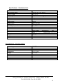
Specifications – Standalone Unit
No. of modules
Input voltage range
Output voltage
Output regulation
Output current
Output current limited
Output ripple
Output noise
Cooling
Operating temperature
Protections
Dimensions
Weight
5
105 to 125 V AC, 60 Hz
27.5 V DC
1%
Continuous
50 A
Surge
55 A
66 A
60 mv
Up to 600 mv
forced air, 2 fans
0 to 40 C
Short circuit
Yes
Fan failure
buzzer
Input surges
Suppression
Yes
Fuse
Module fuse- 125 V 4 A
19” x 14” x 3.6 “
23 LBS
Specifications – Interface Option
Input voltage
Input current - fused
Input current - nominal
Dimensions
Weight
24 VDC
500mA
< 200mA
< 8” x 6” x 2”
< 0.7 LB
Prologic Controls Ltd. 2318-18th Avenue N.E. Calgary, Alberta T2E 8R1
Ph: 403-250-2909 Fax: 403-291-4949
9
Troubleshooting
POWER ON/OFF SWITCH DOES NOT LIGHT WHEN SWITCHED ON
1. Check that power is available in the AC outlet or AC input terminals or that the power cord is
properly plugged in.
POWER SWITCH TRIPS
1. The breaker, which is a part of the power on/off switch, has tripped due to an abnormal
condition. Reset (ie turn on) the switch. If tripping persists call technical support.
“TEMP. FAULT” BUZZER IS SOUNDED
1. One or both of the fans have stopped. Forced cooling has failed due to defect in the cooling
fan(s). Switch off the unit immediately . Fan(s) needs to be replaced.
DO NOT USE THE UNIT TILL THE DEFECT IS RECTIFIED. IT IS PROHIBITED TO USE
THE UNIT WITHOUT FORCED COOLING. Call technical support.
2. If both the fans are running, the small fan status monitoring PCB may be
defective. Call technical support.
“PCB STATUS”
1. The status is ‘0’. The associated module has become defective. The unit will still operate
normally as the remaining working modules will share a higher load. The unit will go into
current limit and the output voltage will drop if the load drawn is more than the combined
maximum rated output of the remaining modules. Reduce the load so that the maximum load
drawn is less than the combined maximum rated output of the working modules. Remove the
defective module and replace with a new module.
2. ONE OR MORE “PCB STATUS” indicators “FLASH” (alternates from ‘1’ to ‘0’). The output
voltage of the individual modules is not the same or the forced shared control circuitry of the
module(s) is defective. Adjust the voltages of the modules to a common voltage as explained
on page 13 Output Voltage Adjustment for a New or Existing Module. If the problem still exists,
contact technical support.
OUTPUT VOLTAGE DROPS
1. The unit has gone into current limit as the load being drawn is more than the combined
maximum rating of the working modules. This may also result if one or more modules has
failed . Check that all the modules are operating properly. Reduce the load drawn to a value
less than the combined maximum rated output of the working modules. If the voltage does not
rise to the rated voltage of 27.6 V, then switch off all the loads. If the voltage in this condition is
also low, switch off the unit and contact technical support.
Prologic Controls Ltd. 2318-18th Avenue N.E. Calgary, Alberta T2E 8R1
Ph: 403-250-2909 Fax: 403-291-4949
10
Limiting Electromagnetic Interference (EMI)
1. Switched mode power supplies ( SMPS ) employ high frequency switching and thus, are a
source of radio interference, a recipient of radio interference and a conduit of radio
interference. ( Older linear type transformer based power supplies do not employ high
frequency switching voltages and will be quieter as compared to switching type supplies ).
2. The primary emission sources originate in the switching devices due to their fast switching
current transitions: harmonics of the switching frequency and broadband noise created by
under-damped oscillations in the switching circuit. The secondary source is from the bridge
rectifier, both rectifier noise and diode recovery. The AC input rectifier / capacitor in the front
end of the switching power supplies ( excepting those with power factor correction ) are
notorious for generating power supply harmonics due to the non linear input current waveform.
The noise is both conducted and radiated through the input power cord and the DC output
wiring to the radio. Filters are used to limit the noise to acceptable level.
3. Switching power supplies are also recipients of radio interference. The normal operation of
the power supply can be disturbed due to RF noise getting coupled into the power supply.
Thus, the power supply may generate excessive RF noise and lose output voltage regulation
due to excessive transmitter energy being coupled through the AC / DC lines to the power
supply’s regulator feedback path. This may be due to antenna being too close or due to the
antenna or feed system not radiating properly. First check the antenna system SWR. Then, if
necessary, relocate either the antenna or the power supply farther apart.
4. The receiver may “hear” the power supply. A slowly moving, slightly buzzing carrier heard in
the receiver may be caused by the antenna being too close. As with the transmitter related
noise pick up, a loose coaxial connector or a broken or a missing ground may aggravate this
problem. Normally these noises will be below the background or “band” noise. Increase the
separation between the power supply and the receiving antenna. Use an outdoor antenna.
This will reduce the amount of signal picked up from the power supply and also increase the
amount of the desired signal.
5. The conducted RF noise from these power supplies is limited to the maximum allowable
levels by internal filtration. The filtered RF noise currents are bypassed to the chassis of the
power supply. The chassis is, in turn connected to the earth ground pin of the AC input power
cord (for Class 1 units). Thus, the filtered noise currents are intentionally leaked to the earth
ground. This is termed as the “Earth Leakage Current”. For safety against electric shock, this
earth leakage current is also required to be limited. It will be seen that these two requirements
are conflicting.
NOTE: In some cases, to prevent electric shock hazard due to abnormal leakage current (like
in marinas, spas, hot tubs, wet spaces etc.), the AC outlet circuits / receptacles in these areas
Prologic Controls Ltd. 2318-18th Avenue N.E. Calgary, Alberta T2E 8R1
Ph: 403-250-2909 Fax: 403-291-4949
11
are served through a GFCI ( Ground Fault Circuit Interrupter ). This GFCI is normally set to trip
when it senses an earth leakage current > 5 mA. A single GFCI may be serving multiple AC
outlet circuits / receptacles and therefore, will be sensing the sum of all the leakage currents of
the devices connected to these. As the switching power supplies have intentional leakage
current as explained above, it may trip a GFCI feeding multiple AC outlet circuits / receptacles.
In such cases, disconnect devices connected to the other AC outlet circuits / receptacles
served by this GFCI.
6. Following additional guidelines may be followed to reduce the effects of RF noise:
a. Use additional appropriate AC radio frequency interference (RFI) power line filter
immediately before the ac input of the power supply. Recommended: Corcom Inc.
(www.cor.com ) “Q” series. Filtered, ferrite coated cord set (www.emceupen.com ) is another
choice. These cord sets, with integral line interference filters, reduce common and differential
mode interferences over a wide frequency range. Because they are shielded, they are also
effective against radiated interferences. In addition to the built-in filter networks, the cable
conductors are coated with an RF absorbing ferrite compound. This provides additional
attenuation at high frequencies that is lacking in most regular LC filters. The RF absorption of
the ferrite-coated cable avoids resonance’s at high frequencies, reducing the conducted and
radiated RF noises even further.
b. Use additional appropriate DC radio frequency interference (RFI) power line filter
immediately after the dc output of the power supply. Recommended: Corcom
Inc.(www.cor.com ) “DA” / “DC” series.
c. Twist the positive and negative wires from the output of the power supply to the radio.
d. The DC side positive and negative outputs of these power supplies are isolated from the
chassis. As explained at paragraph 5 above, the noise currents are filtered to the chassis
ground and the chassis ground is connected to the earth ground through the earth ground pin
of the AC power outlet receptacle. Avoid connecting (referencing) the DC negative output
terminal of the power supply to the earth ground.
e. Connect a 1/4 wave length of wire on the negative terminal of the power supply. Connect
one end of the wire to the negative terminal and leave the other end free. The wave length
corresponds to the wave length of the interfering frequency. (May not be practical for long
wave lengths)
Formula: Wave length (Meters) = 300 / frequency in MHz
Prologic Controls Ltd. 2318-18th Avenue N.E. Calgary, Alberta T2E 8R1
Ph: 403-250-2909 Fax: 403-291-4949
12
LIMITED WARRANTY
The equipment manufacturing for Prologic Controls ltd. (The “Warrantor”) is warranted to be free from defects is
workmanship and materials under normal use and services. This warranty is in effect for 1 year from the date of
purchase by the used and service. The warranty is in effect for 1 year from the date of purchase by the user (The
“Purchaser”)
In case any part of the equipment proves the defective; the purchaser should do the following:
-Prepare a written statement illustrating the nature of the defect to the best of the Purchaser’s knowledge, and
include the date of purchase, the place of purchase, and the Purchaser’s Name, address, and telephone number.
-Call Prologic Controls Ltd. 1(403)250-2909 or Fax 1(403)291-4949 and request a returning merchandise
authorization number (RMA)
-Return the defective part or unit along with the statement (at the Purchaser’s expense) to the Warrantor: Prologic
th
Controls Ltd. 2318 18 Ave NE Calgary, AB T2E 8R1 Canada. The RMA number must be marked clearly on the
outside of the packaging. Make sure the following is attached:
Original Bill of Sale
Date Purchased
Place of purchase
Purchase price
Serial number
If upon the Warrantor’s examination the defect proves to be a result of defective material or workmanship, the
equipment will be repaired or replaced at the Warrantor’s option without charge, and returned to the Purchaser at
the Warrantor’s expense.
No refund of the purchase price will be granted to the Purchaser, unless the Warrantor is unable to remedy the
defect after having a reasonable number of opportunities to do so. Warranty services shall be performed only by
the Warrantor. Any attempt to remedy the defect by anyone other than the Warrantor shall render this warranty
void.
There shall be no warranty for defects or damage caused by faulty installation or hook-up, abuse or misuse of the
equipment including exposure to excessive heat, salt or fresh water spray, or water immersion.
No other express warranty is hereby given and there are no warranties which extend beyond those described
herein. This warranty is expressly in lieu of any other expressed or implied warranties, including any implied
warranty of merchantability, fitness for the ordinary purpose for which such goods are used, or fitness for a
particular purpose, or any other obligations on the part of Warrantor or its employees and representatives.
There shall be no responsibility or liability whatsoever on the part of the Warrantor or its employees and
representative for injury to any persons, or damage to person or persons, or damage to property, or loss of
income or profit, or other consequential or resulting damage which may be claimed to have been incurred through
the use or sale of the equipment. Including any possible failure of malfunction of the equipment, or part thereof.
The Warrantor assumes no liability for incidental or consequential damages for any kind.
R1.3 April 23, 2012 – Trecon Prologic Technical Support Tel: 403-250-2909 Fax: 403-291-4949
Prologic Controls Ltd. 2318-18th Avenue N.E. Calgary, Alberta T2E 8R1
Ph: 403-250-2909 Fax: 403-291-4949
13