1
FP-08 Programming Panel
User’s Manual
V1.1
Fatek Automation Corp.
14/07/2009
Contents
1 Introduction to FP-08 ...........................................................................................1
1.1 Appearance ...................................................................................................1
1.2 Keypads Arrangement ..................................................................................1
1.3 Memory Pack (FBs-PACK) Programmer .....................................................2
1.4 RS-232 COM Port and FP-08 OS Update.....................................................2
1.5 Interface Connection between FP-08 and PLC .............................................3
2 Program Edit, Run, Monitor, Forced Set/Reset and Enable/Disable ...................3
2.1 Program Edit .................................................................................................3
2.2 Program RUN................................................................................................6
2.3 Program Execution Monitoring ......................................................................7
2.4 Forced Set/Reset and Enable/Disable of Digital Status ................................9
2.5 Set the Register Data....................................................................................10
3 The Functions of FP-08 .......................................................................................11
3.1 Functions List ................................................................................................11
3.2 Operation Flowchart......................................................................................14
4 Introduction to SYSTEM MODE Operation .........................................................16
4.1 CLEAR/INITIAL .............................................................................................16
4.1.1 CLEAR PROGRAM....................................................................................16
4.1.2 CLEAR REGISTER....................................................................................17
4.1.3 CLEAR COIL STATUS...............................................................................17
4.1.4 ENABLE ALL DIGITAL...............................................................................17
4.1.5 SYSTEM INITIAL .......................................................................................18
4.1.6 DISABLE ALL DIGITIAL.............................................................................18
4.2 MEMORY PACK OPERATION .....................................................................19
4.2.1 LOAD LAD/REG WHEN POWER ON........................................................19
a) LOAD LADDER WHEN POWER ON ...........................................................19
b) LOAD REGISTER EVERY POWER ON ......................................................19
4.2.2 MEMORY PACK ON PLC ..........................................................................20
a) COPY (LADDERÆPACK)............................................................................20
b) COPY (LAD+REGÆPACK) .........................................................................21
c) SYSTEM BACKUP WITHOUT PLC ID.........................................................22
d) SYSTEM BACKUP WITH PLC ID................................................................22
e) ERASE PACK ..............................................................................................23
4.2.3 MEMORY PACK ON FP-08 .......................................................................23
a) COPY (LADDERÆPACK)............................................................................23
b) COPY (LAD+REGÆPACK) .........................................................................24
C-1
c) SYSTEM BACKUP WITHOUT PLC ID.........................................................25
d) SYSTEM BACKUP WITH PLC ID................................................................25
e) ERASE PACK ..............................................................................................26
f) COPY (PACKÆPACK) .................................................................................26
g) LOAD LADDER (PACKÆPLC) ....................................................................27
h) LOAD ALL (PACKÆPLC) ............................................................................27
i) COMPARE LADDER (PACK←→PLC) .........................................................28
j) COMPARE (PACK←→PACK) ......................................................................28
4.3 PASSWORD/ID.............................................................................................29
4.3.1 PASSWORD OPEN ...................................................................................29
4.3.2 PASSWORD CLOSE .................................................................................30
4.3.3 PASSWORD (ALL) SETTING ....................................................................30
4.3.4 PASSWORD (SUB) SETTING ...................................................................31
4.3.5 PROGRAM ID SETTING............................................................................31
4.3.6 PLC ID SETTING .......................................................................................32
4.4 CONFIGURATION ........................................................................................33
4.4.1 INTERNAL COIL PARTITION ....................................................................34
4.4.2 STEP COIL PARTITION ............................................................................34
4.4.3 0.01S~1S TIMER PARTITION ...................................................................35
4.4.4 16-BIT COUNTER PARTITION..................................................................35
4.4.5 32-BIT COUNTER PARTITION..................................................................36
4.4.6 DATA REGISTER PARTITION ..................................................................36
4.4.7 READ-ONLY REGISTER ASSIGNMENT ..................................................37
4.4.8 HSC/HST/INT ASSIGNMENT ....................................................................37
4.4.9 PSO0~3 SETTING .....................................................................................38
4.5 SYSTEM MESSAGE.....................................................................................38
4.6 SETTING ......................................................................................................39
4.6.1 SET PLC STATION NO. ............................................................................39
4.6.2 SELECT BAUD RATE OF PORT0~4.........................................................39
4.6.3 VOLUME ....................................................................................................40
5 Operation of EDIT MODE....................................................................................41
5.1 EDIT PROGRAM ..........................................................................................41
5.1.1 Sequential Instruction Editing.....................................................................43
a)Fundamental Key Operations of Sequential Instruction ................................43
b)Input the Instruction ......................................................................................45
c)Insert the Instruction......................................................................................45
d)Change Instruction........................................................................................46
e)Delete Instruction ..........................................................................................46
C-2
f)Edit the Element Documents..........................................................................47
5.1.2 Edit Function Instruction.............................................................................48
5.1.3 Search Program .........................................................................................50
5.1.3.1 Search Address.......................................................................................50
5.1.3.2 Search Instruction ...................................................................................51
5.2 EDIT REGISTER DATA ................................................................................54
5.3 SYNTAX CHECK ..........................................................................................57
5.3.1 Key Operation of Syntax Check .................................................................58
5.3.2 Syntax Error List.........................................................................................58
5.4 MOVE(HRÆROR) ........................................................................................60
5.5 CHECK DOUBLE COIL/T/C..........................................................................60
5.6 EDIT HSPSO INSTRUCTION .......................................................................61
5.6.1 Fundamental Key Process of HSPSO Instruction ......................................62
5.6.2 Supplementary Editing Keys for NC Program Editing ................................63
5.6.3 Editing Example .........................................................................................64
5.7 EDIT LINK INSTRUCTION............................................................................65
5.7.1 Supplementary Editing Keys ......................................................................66
5.7.2 Editing Example .........................................................................................66
5.8 EDIT DOCUMENT ........................................................................................67
6 The Operation of MONITOR MODE....................................................................68
6.1 STATUS/DATA MONITORING .....................................................................68
6.1.1 Digital Status Monitoring ............................................................................69
6.1.2 Register Data Monitoring ...........................................................................69
6.1.3 Change the Register Data..........................................................................70
6.2 PROGRAM MONITORING ...........................................................................70
7 PLC Run/stop control ..........................................................................................71
C-3
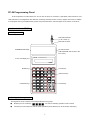
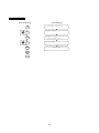
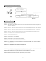
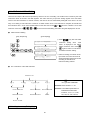
FP-08 Programming Panel
FP-08 Programmer for FBs series PLC can be used to edit PLC mnemonics, high-speed pulse instructions, and
LINK instructions. The programmer also features: monitoring and setup of timer, counter, register and contact; in addition
to the program memory pack (FBs-PACK), system setup and information, and user update of OS version on FP-08 etc.
1
Introduction to FP-08
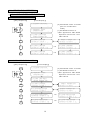
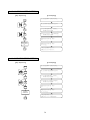
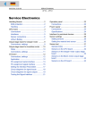
1.1
Appearance
FBs-232P0-9M-200
( to PLC Port1~4)
Mini-DIN connector
EPROM/EEROM writer
RS-232connector
(FBs-232P0-9M-200 connect to the
PLC Port0)
16 X 2 LCD display unit
FP-08
PROGRAMMING PANEL
FATEK
MODE keys
SYS
MODE
EDIT
MODE
AND
_
+
LD
X
Y
Parameter keys
M
S
OR
U
L
H
D
SHIFT
1.2
RUN
STOP
=
TU <
TD
>
"
ORG
MON
MODE
T
7
4
1
V
N
I
E
SHORT
0
OPEN
OUT
FO *
NOT
C
8
5
2
P
Z
0
J
F
A
EN
DIS
MAN
SUB
SET '
RST
TO :
FROM
/
(
)
FUN
END
STP
R
CLR
SCH
DEL
INS
9
6
3
Instruction keys
Q
K
HEX
DEC
Control keys
G
WB
TR
Control keys
ENT
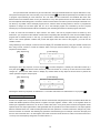
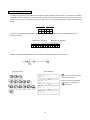
Keypads Arrangement
The keypads of FP-08 console is functionally divided into four groups:
●
Mode keys: Four mode keys,
●
Control keys: Control keys are used for mode operations (all the blue keys on FP-08 except mode keys).
, are used for selecting operation mode of FP-08.
1
●
Instruction keys: Instruction keys are used for entering FBs-PLC instructions with parameters or data. All the
black keys in the top two rows and the two keys,
at the fourth row of FP-08 (refer to
the description of special keys below) are the instruction keys.
●
Parameter keys: Parameter keys are used for entering the operand’s numbers or contents. All black keys,
except instruction keys, are parameter keys.
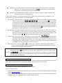
In order to obtain optimum convenience and maximum input capability under a limited number of available keys, four
groups of keys are designed as multi-purpose as described below:
a.
Alternation keys: Alternation keys are those with a horizontal line marked in the middle to separate two distinct
). By pressing the key (
functions (a total of six keys,
as an example)
for the first time, the function above the horizontal line (RUN) will be displayed on the LCD display unit.
By pressing the key again, the function below the horizontal line (STOP) will be displayed. If the key is
pressed for the third time, the LCD screen will display the function above the horizontal line (RUN) again.
The process will repeat if the key is pressed repeatedly. By pressing
(at the lower rightmost corner of
the keypads), the function last shown on the LCD screen will take effect.
b.
Shift Key: After pressing this orange key (at the lower leftmost corner of the keypads), an S letter will first appear on
the LCD display unit. If now any key at the upper rightmost corner with a small orange letter printed is
pressed, the small orange letter (the “shift key letter”) will be entered or the function described by the
orange letter (such as
c.
or
) will be executed and the letter S on the LCD will disappear.
Compound keys: There are two rows of white letters on each of the four keys,
,
those are neither
shift keys nor alternation keys but keys that can perform the two functions represented by the two rows of
white letters. Under special arrangement when one of these keys is pressed, FP-08 will carry out the
function described by either the upper or the lower row in accordance with the current operation mode
automatically without any further instruction given by the user.
d.
Double-definition keys: Two keys,
and
, represent Timer and Counter, respectively and also the letters T
and C. Similar to the compound keys, the two functions cannot be operated simultaneously. FP-08 will
make necessary judgment itself automatically.
Remark 1: Pressing two or more keys at the same time is prohibited while operating the FP-08 programming panel. For
example, after the key
Remark 2:
being pressed, it must wait until it is released before the next key can be pressed.
keys are used for moving the cursor by one position to the direction of the arrow whenever
one of these four keys is pressed. The cursor will move rapidly if one of these keys is pressed for more than
0.7 second without being released.
1.3
Memory Pack (FBs-PACK) Programmer
The memory pack FBs-PACK is a 1M bits FLASH ROM for storing the FBs program and register data. The memory
pack can also be write-protected. We can put FBs-PACK on FP-08 or PLC main unit to write/read it.
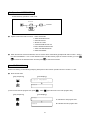
1.4
RS-232 COM Port and FP-08 OS Update
RS-232 COM port currently supports updating the OS version of FP-08.
FP-08 OS update procedure:
1. Download “PP Boot” software and the latest FP-08 OS version from the “Technical Support” section of the FATEK
website http://www.fatek.com
2. Open the cover of the FP-08 Programmer and align the 3 pins at the left to the 2 pins position along the bottom.
Connect to a PLC Port 0 until the message “FP-08 OS UPDATE” is shown.
2
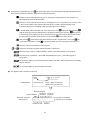
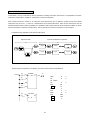
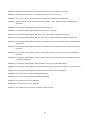
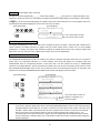
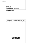
3. Use FBs-232P0-9F-150 with different packaging (where the pin 2 and 3 of the RS232 port must be switched around,
shown in bellow) and connect to the RS-232 port on the PC. (If a RS232 port is not readily available, please use the
“USB to RS232 adaptor”)
4. Launch the FATEK ”PP Boot” software and follow the procedures:
(1) Go to “File” and select the latest OS version.
(2) Choose the RS232 [Com Port] connection, press Open Com Port button and OS Update Start button will be
highlighted, indicating the COM Port is correct.
(3) Press OS Update Start button to begin updating the OS version.
D-SUB (Female)
9
5
Mini-DIN
(male)
G
Vcc
4
FP08 OS update cable
8
( correct with FBs-232P0-9F-150)
7
6
3
2
RXD
2
4
TXD
1
Shield
1
3
Top view
Top view
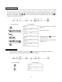
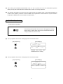
1.5
Interface Connection between FP-08 and PLC
Since FP-08 does not have its own power supply, therefore all of its operations can only be carried out after the
connection between FP-08 and the PLC main unit is completed by using an unique FP-08 communication cable
(FBs-232p0-9M-150). If all operations are functioning normally , FP-08 will display the PP initiating screen as shown
below. It indicates that the connection has been established and is ready for operation.
2
Program Edit, Run, Monitor, Forced Set/Reset and Enable/Disable
A simple example program is illustrated in this section to show how to edit (input) the control programs, to run or stop the
PLC, to use the monitor mode to examine the program execution results while the PLC is running, to forced set/reset the
status of digital point or set the value of register, to enable/disable the digital points by using the FP-08 with a fast and
efficient way.
2.1
Program Edit
Please ensure that the program area in the PLC is empty (i.e. no program remained) before program editing for this
example. The following keys can be used to clear the program area (This step can be omitted for a newly purchased PLC
since the “CLEAR” operation has been performed before the shipment from the factory)
【Key Sequence】
【LCD Display】
3
key to enter the edit mode.
After verifying that the program area is empty, press the
【Key Sequence】
【LCD display】
The above LCD display, "" indicates the current address in a program, and "" indicates the main program
area. 0000M means now we are at the beginning of the main program area. Following input instructions will occupy the
areas 0001M, 0002M, 0003M and so on. When you enter the edit mode for the first time, FP-08 will enter the main
program area automatically.
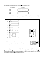
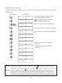
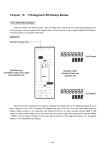
Y0
X0
(1)
Y1
Y2
M1922
(2)
Y3
X2
X1
(3)
Y3
X3
(4)
1S
EN T200
10 TUP
(5)
X4
CK
(6)
C
0
PV :
X5
X
0
OUT
Y
0
OUT NOT
Y
1
ORG
M1922
OUT
Y
2
ORG
X
1
OR
Y
3
AND NOT
X
2
OUT
Y
3
ORG
X
T200 PV:
Y4
T200
ORG
CUP
20
ORG
T
200
OUT
Y
4
ORG
X
4
LD
CLR
X
C0
Y5
C0
(7)
3
10
PV:
5
20
ORG
C
0
OUT
Y
5
• (1)~(7) indicate the starting points of the network.
• X0~X5,Y0~Y5,M1922 etc. Please refer to Chapter 3.
• Please refer to Chapter 5 through Chapter 8 for detail description of
※the characters in
by
functionality of instruction used above.
are
the directive string shown
FP-08 which are not
entered by the user.
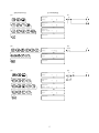
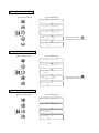
The following demonstration illustrates the programming procedures of the sample program shown above. The
instructions are displayed on the LCD screen. If typing error occurs during the programming process before pressing the
key, simply press the
key to clear the incorrect instruction. If a typing error is detected after pressing the
key to delete the incorrect instruction or key in the correct
you must find the incorrect instruction first then press the
instruction directly and press the
key,
key to replace the incorrect one.
4
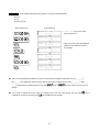
【Key Sequence】
【LCD Display】
(1)
(1)
Y0
X0
Y1
(2)
(2)
Y2
M1922
(3)
(3)
X1
Y3
5
X2
Y3
(4)(5)
(4)(5)
X3
1S
EN T200
10 TUP
Y4
T200
(6)(7)
(6)(7)
X4
CK
C
PV :
X5
0
CUP
20
CLR
C0
Y5
After entering all the instructions of a program, can continuously depress
to the start of ladder program (Similarly can either continuously press
of the ladder program) then depress
or press
or press
to let the edit point back
keys to get to the end point
successively to check if the mnemonic codes are correct or not. If everything is
correct, then it is the time to run the program.
2.2
Program RUN
After pressing
, there will be a message displayed on LCD asking you whether you want to change to RUN (if the
PLC is currently at STOP state) or to STOP (if the PLC is at RUN state). Press
below:
6
to execute your choice as shown
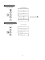
( 1 ) Changing PLC from STOP to RUN:
【Key Sequence】
【LCD Display】
( 2 )Changing PLC from RUN to STOP:
【Key Sequence】
【LCD Display】
If you want to monitor the program execution of the example program, you must let the PLC in RUN state. So please first
repeat the step(1) as shown above. After the PLC turns to RUN state, you can examine the program execution results by
entering the monitor mode which will be described in the next section.
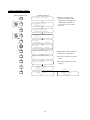
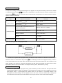
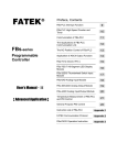
2.3
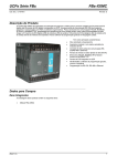
Program Execution Monitoring
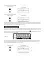
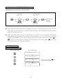
To monitor the execution status of this application, please first connect the S/S port to the 24V+ with a wire. Then use
another wire (C-wire) to connect the 24V- to the input of X0~X5 – utilizing the analog switching as shown in Figure <1>
below. (The other way to do this is to disable the input of X0~X5 first and then use
to SET/RST the state of X0~X5.
Please refer to the last section of Section 2.4)
Figure <1>
max.
400mA
24V OUT
S/S
X0
X2
X1
X4
X3
X6
X5
X7
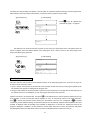
If you want to monitor the program execution results (the digital status or the data registers), you need to use function
item 1 of the monitor mode which is called “STATUS/DATA MONITORING” . Following key operations shows a way to
enter the “STATUS/DATA MONITORING” of the monitor mode.
【Key Sequence】
【LCD Display】
c
d
indicates the Monitor mode status
7
Under the Status/Data monitoring mode, LCD screen can monitor two rows of data at the same time. But only one row of
data that pointed by cursor can be entered at a time. Using the Row Change
, can move the cursor between these
two rows. In the following key operations, the first row shown in the LCD screen is for monitoring the digital status and the
second row shown in the LCD screen is for monitoring the register data.
【Key Sequence】
【LCD Display】
e
It indicates the X3 status is at "0"
It indicates X3 is Enabled (refer to
2.2.4 for more details)
After X3 status appears on the LCD screen, can use
Starting with the message shown in LCD display
e, if you press
status will display on the LCD screen if you press
on, press
to monitor the preceding or the succeeding contact points.
once, X2 status appears on the LCD screen. X1
one more time. If you want to monitor the status of X4, X5 and so
to get this.
【Key Sequence】
After pressing
【LCD Display】
f
g
h
, the cursor now will move to the second row (the LCD display of first row remains unchanged). The
rest of the input and operations will all be taken place at the second row.
【Key Sequence】
【LCD Display】
i
j
It indicates the current value of C0
register is at 0
It indicates the contact point C0 status
is at 0
In the above LCD display, the second row shows an example of monitoring register data. The message shown in this row
indicates the C0 contact point status (the status is at “1” if the counter value is equal to the preset value), and the current
value (counter value) of the C0 register.
When the LCD display shown above appears, can use the conducting wire C to touch the external input point X0~X5 to
test this program. The operating results can be seen from PLC’s output points(Y0~Y5). Furthermore, can use this
monitoring display to examine the data that the output points (Led indicators) unable to show, such as the status of
internal contact points, the current value and contents of T and C registers. The description of the functionality of the
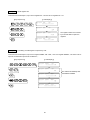
example program and the relationship of corresponding I/O points are listed in the table below. You can conduct your own
experiments according to this table and observe the operating results
8
Network
Number
(1)
(2)
(3)
(4)
(5)
Relationships between input (Xn)
and Output (Yn)
X0=1 then Y0=1, Y1=0
X0=0 then Y0=0, Y1=1
Description of the circuit functions
This network sends the X0 status to Y0
and then inverts the X0 status and sends
the results to Y1.
Sends the internal contact M1922 status
(1 second)to Y2.
Latch Circuit:X1 is the starting contact,
as soon as X1 turns “ON”, Y3 turns “ON”
and retains the statuses. X2 is a reset
contact. As soon as X2 turns” ON”, Y3
turns “OFF” and retains the status.
Y2 switches ON/OFF once every second
(not input related)
If X1”ON” then Y3”ON”
If X2”ON” then Y3”OFF”
10 seconds Timer
If X3”ON”, after 10 seconds, Y4”ON”
If X3”OFF”, Y4“OFF” immediately
20 times Counter (counts 20 times)
Register C0 increments 1 for every X4
switching from OFF to ON until C0=20, Y5=1
If X5”ON”, then register C0 clears to 0 and
contact C0 is also at 0, therefore Y5=0
(6)
(7)
As shown in Display
j, every time the conducting wire C as shown in Figure <1> touches the input point X4, the current
value of the register C0 will automatically increment by 1.(Remark: the current value of the register C0 may increment by
more than one because several pulses may have been generated for each touch due to bouncing) The status of contact
C0 switches to 1 when register C0 value reaches 20 as shown in Displayk. If the conducting wire C touches input point
X5, then the status of contact returns C0 to 0 as shown in Display
l. Every time turn-on the PLC, the display format of
current value of register C0 is in decimal number. If you want to display the value in hexadecimal number, press
To return to the decimal number, press
.
After the conductive wire C touches
k
l
the X4 input point 20 times
After the conductive wire C touches
the input point X5
2.4
Forced Set/Reset and Enable/Disable of Digital Status
While in the monitor mode, for digital points, not only can monitoring its status, but also can force its status by using the
keypad
of FP-08. In general, forced set/reset is often used for the diagnosis and program testing purpose. The
following key sequence continues the operation shown in Display l. It demonstrates a key operation procedure of forced
set/reset while monitoring the Y6 status. Y6 status is forced set to 1 first, and then is forced reset to 0.
【Key Sequence】
【LCD Display】
9
Forced set to 1
Forced reset to 0
.
For input contacts with coils driven by an OUT instruction, the forced set/reset status can only be retained for a very
short period of time (less than one scan time). Very soon the forced
status will be replaced by the new status of input
or program output following an OUT instruction. PLC I/O status and OUT instructions are refreshed after each scan
therefore the forced set/reset status can only be retained for a very short period which is the time between status forced
and new replaced status taking place. The reason of the forced set status can retain in previous example is because Y6 is
not driven by any ladder code in example program, that is, after the status is being written-in, there is no programmed
operation to change the Y6 status again. But Y0~Y5 in the example program are controlled by the PLC program
meaning any forced set/reset status will be overwritten by the new data generated from further program executions.
In order to forced set the statuses of input contacts(X0~X255)and coils of programs which are driven by OUT
instructions, you must perform the “Disable” function first to temporarily allow the data out of the control of ladder diagram
program and I/O refresh process. In this way, you will be able to retain the data while performing the data change. To
return to the normal operation condition and put the data again under the control of the program, you must use the
“Enable” function.
Using network (6) as an example, continuous from the display
l, first disable the X4 by using the “Disable” function and
then using “Forced” function to control the ON/OFF state of X4 input contact instead of using the C wire. The key in
sequence is shown below.
【Key Sequence】
【LCD Display】
Following the above key sequence, as soon as press
every time press
, C0 value changes to 1 instantly. C0 value will increment by 1
twice until this value reaches 20. When C0 reaches 20, “Count Up” is done and the contact status
changes to 1 (same as the status shown in Display
k). Please follow the key sequence shown below to perform the
“Clear” operation using the X5 input point.
【Key Sequence】
【LCD Display】
Following the above key sequence, X5 will switch to 1. The value and status of C0 will all clear to 0 if you press
2.5
.
Set the Register Data
Similar to the digital status, the register data can also be monitored and changed (forced set) in the Monitor Mode. But the
enable and disable operations cannot perform to register. The input registers(R3840~3903)or the registers which are
written by the application instructions, can be set to certain value, but in a very short period of time those registers will be
replaced by the new input register data or data generated from the operations of function instructions. The input registers
data are refreshed each scan, while the data generated from the operations of function instructions changes only when
function instruction is executed. The following key operations uses Network (6) as an example. First touch the input point
X5 once with conductive wire C to clear register, then enter the monitor mode and set C0 value to 20 which cause C0 to
“Count Up” and consequently change the C0 contact status to 1.
10
【Key Sequence】
【LCD Display】
The current value of C0 is
forced set to 20
The current value of C0 is forced set to 20. The
contact status of contact C0 changes to 1
because the current value of C0 now is equal to
the preset value (i.e. count-up) is done.
3 The Functions of FP-08
3.1
Function List
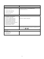
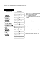
There are four operating modes for FP-08, which are System Mode, Edit Mode, Monitor Mode and RUN/STOP Mode.
The function descriptions for each mode are listed at below.
●
◎indicates the operable items when the password has not been closed.
System Mode
Function
Descriptions
1. CLEAR/INITIAL
1) CLEAR PROGRAM
• Including Documents, Password, Program ID, Configuration, ROR
(Read Only Register) data
2) CLEAR REGISTER
3) CLEAR COIL STATUS
4) ENABLE ALL DIGITAL (contact and coil)
• Enables all contacts
5) SYSTEM INITIAL
6) DISABLE ALL DIGITAL (contact and coil)
• Clears all data, returns PLC to its initial factory settings
2. MEMORY PACK OPERATION
◎ 1) LOAD LAD/REG WHEN POWER ON
◎ 2) MEMORY PACK ON PLC
◎ 3) MEMORY PACK ON FP-08
• Set special register R4052 and R4046,please refer to appendix 3
“FBs-PACK Operation Instruction” from FBs manual.
• Memory pack(FBs-PACK) operation include copy,load,compare,
system backup,and system restore.
11
Function
Descriptions
3. PASSWORD/ID
◎ 1) PASSWORD OPEN
•
These two functions are only applicable after the
◎ 2) PASSWORD CLOSE
•
password has been set
◎ 3) PASSWORD (ALL) SETTING
◎ 4) PASSWORD (SUB) SETTING
◎ 5) PROGRAM ID SETTING
◎ 6) PLC ID SETTING
4. CONFIGURATION
◎ 1) INTERNAL COIL PARTITION
◎ 2) STEP COIL PARTITION
◎ 3) 0.01S~1S TIMER PARTITION
Please refer to “Default Configuration”
◎ 4) 16-BIT COUNTER PARTITION
◎ 5) 32-BIT COUNTER PARTITION
◎ 6) DATA REGISTER PARTITION
◎ 7) READ-ONLY REGISTER PARTITION
◎ 8) HSC/HST/INT ASSIGNMENT
◎ 9) DEFINE NORMAL POLAR.
5. SYSTEM MESSAGE
Once in this mode, will be able to observe PLC and PP versions,
memory usage, password setting and system configurations and
more by pressing
6. SETTING
◎ 1) PLC No. Setup
2) PORT Baud Rate
3) FP-08 Volume
12
or
●
Edit Mode
Functions
Descriptions
◎ 1 .EDIT PROGRAM
2 .EDIT REGISTER DATA
3 .SYNTAX CHECK
4 .MOVE HRÆROR
5 .CHECK DOUBLE COIL/T/C
6 .EDIT HSPSO INSTRUCTION
7 .EDIT LINK INSTRUCTION
8 .EDIT DOCUMENT
●
Monitor Mode
Functions
Descriptions
1. STATUS/DATA MONITORING
◎ 2 .PROGRAM MONITORING
Can monitor the program with the contact status display
while PLC is in RUN state
●
RUN/STOP Mode
Functions
Descriptions
PLC RUN/STOP Control
13
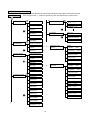
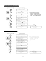
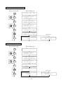
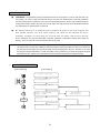
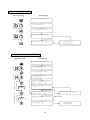
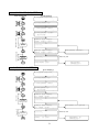
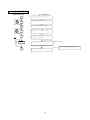
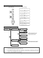
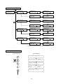
3.2
Operation Flowchart
The diagram shown at below is the operation flowchart for System Mode, Edit Mode, Monitor Mode and RUN/STOP Mode.
A . SYS M O D E
Note: Items prefix with ◎ symbol can operate only when the password has not been closed.
SYS
MODE
1.CLEAR/INITIAL
ENT
_
1)CLEAR PROGRAM
2)CLEAR REGISTER
_
_
4)ENABLE ALL
DISCRETE
_
6)DISABLE ALL
DISCRETE
ENT
PLC : V×.××
FP08 : V×.××
STATION NO. : 1
IN LADDER? : NO
_
3)CLEAR COIL
STATUS
5)SYSTEM INITIAL
5.SYSTEM MESSAGE
_
6.SETTING
_
◎
1)SET PLC
STATION NO.
_
2)SELECT BAUD
RATE OF PORT0~4 _
_
3)VOLUME
ENT
2.MEMORY PACK
OPERATION
_
_
1)COPY LAD/REG
◎ WHEN POWER ON _
◎
2)MEMORY PACK
ON PLC
_
α
◎
3)MEMORY PACK
ON FP-08
_
β
3.PASSWORD/ID
1)PASSWORD OPEN
_
◎
2)PASSWORD
CLOSE
4.CONFIGURATION
_
_
◎
4)PASSWORD(SUB)
SETTING
_
◎
5)PROGRAM ID
SETTING
a)COPY
LADDER → PACK
b)COPY
(LAD+REG) → PACK
c)SYSTEM BACKUP
WITHOUT PLCID
d)SYSTEM BACKUP
WITH PLCID
_
3)PASSWORD(ALL)
SETTING
_
ENT
2)MEMORY PACK
ON PLC
_
◎
6)PLC ID SETTING
α→
e)ERASE PACK
β→
3)MEMORY PACK
ON FP-08
_
a)COPY
LADDER → PACK
_
b)COPY
(LAD+REG) → PACK
_
c)SYSTEM BACKUP
WITHOUT PLCID
d)SYSTEM BACKUP
WITH PLCID
◎
1)INTERNAL COIL
PARTITION
_
◎
2)STEP COIL
PARTITION
_
◎
3)0.01S→1S TIMER
PARTITION
_
f)COPY
PACK → PACK
◎
4)16-BIT COUNTER
PARTITION
_
g)LOAD
PACK → PLC
◎
5)32-BIT COUNTER
PARTITION
_
h)LOAD ALL
PACK → PLC
◎
6)DATA REGISTER
PARTITION
i)COMPARE LADDER
PACK → PLC
◎
7)READ-ONLY REG.
ASSIGNMENT
_
◎
8)HSC/INTERRUPT
ASSIGNMENT
_
◎
9)PSO0→3 SETTING
(DEFINE Y0→Y3) _
e)ERASE PACK
_
j)COMPARE
PACK → PACK
14
B. EDIT MODE
5.CHECK DOUBLE
COIL/T/C
_
1.EDIT PROGRAM
_
◎
2.EDIT REGISTER
DATA
_
6.EDIT HSPSO
INSTRUCTION
_
3.SYNTAX
7.EDIT LINK
INSTRUCTION
_
4.MOVE
CHECK
_
8. EDIT DOCUMENT
HR→ROR
_
C. MONITOR MODE
◎
1.STATUS/DATA
MONITORING
_
2.PROGRAM
MONITORING
_
D. RUN/STOP MODE
RUN ?
PRESS ‘ENT’
←PLC currently is at STOP
STOP ?
PRESS ‘ENT’
←PLC currently is at RUN
15
4
Introduction to SYSTEM MODE Operation
Fundamental key operations of System Mode:
Selecting the first level main
Selecting the second level
functions
sub-functions
(n=1~ 7)
(m=1~ C)
↓
↓
Execution of
selected
functions
● System Mode includes eight main operation functions. N indicates the nth main function.
Every main function also has n numbers of sub-functions. m indicates the mth sub-function
within the nth main function.
● When you enter either the first or second level of function for the first time, you will be
automatically prompted into main function 1 or sub-function 1 [n=1 or m=1]. If this is not the
function you needed, you can either directly input the function number (n) or using
to search for the specific function you are looking for and then press
or
to execute
the function which you have just selected.
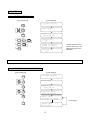
4.1
4.1.1
CLEAR/INITIAL
CLEAR PROGRAM
【 Key Sequence】
【 LCD Display】
16
y Any keys except
cancel the function
will
4.1.2
CLEAR REGISTER
【 Key Sequence】
【 LCD Display】
y Any keys except
will cancel the function
4.1.3
CLEAR COIL STATUS
【 Key Sequence】
【 LCD Display】
4.1.4
ENABLE ALL DIGITAL
【 Key Sequence】
【 LCD Display】
17
y Any keys except
will cancel the function
4.1.5
SYSTEM INITIAL
【 Key Sequence】
【 LCD Display】
4.1.6
DISABLE ALL DIGITAL
【 Key Sequence】
【 LCD Display】
18
y Any keys except
will cancel the function
4.2
MEMORY PACK OPERATION
◎ 4.2.1
LOAD LAD/REG WHEN POWER ON
a)LOAD LADDER WHEN POWER ON
【 Key Sequence】
SYS
MODE
2
F
【 LCD Display】
(1) EN:R4052 writes in 0.
ENT
ENT
(test run modification
mode)
ENT
0
OR
1
(0) DIS:R4052 writes in 5530H
※ R e f . A p p e n d i x 3 “ F B s - PA C K
Operation Instruction” from
FBs manual.
OR
OR
b)LOAD REGISTER EVERY POWER ON
【 Key Sequence】
SYS
MODE
2
F
【 LCD Display】
(0) DIS:R4046 writes in 5530H
(1) EN:R4046 writes in 0.
※ R e f . A p p e n d i x 3 “ F B s - PA C K
Operation Instruction” from
FBs manual.
ENT
ENT
0
OR
1
ENT
OR
OR
19
◎ 4.2.2
MEMORY PACK ON PLC
a)COPY (LADDER→PACK)
【 Key Sequence】
SYS
MODE
2
F
ENT
2
F
ENT
ENT
【 LCD Display】
20
Fail
b)COPY (LAD+REG→PACK)
【 Key Sequence】
SYS
MODE
2
F
ENT
【 LCD Display】
※Before operate this
function, please take
reference of Appendix 3
“ F B s - PA C K O p e r a t i o n
Instruction” from FBs
manual.
2
F
ENT
ENT
ENT
● T h e f i r s t r e g i s t e r ’s i n i t i a l
code
ENT
● T h e f i r s t r e g i s t e r ’s d a t a
length
ENT
ENT
21
● F B s - PA C K r e a d s b a c k a t
maximum 4 registers.
Fail
c)SYSTEM BACKUP WITHOUT PLC ID
【 Key Sequence】
SYS
MODE
2
F
【 LCD Display】
※The function of system
backup includes ladder、
r e g i s t e r、d i g i t a l a n d s y s t e m
ENT
data, but PLC ID excluded.
2
F
ENT
ENT
Fail
d)SYSTEM BACKUP WITH PLC ID
【 Key Sequence】
SYS
MODE
【 LCD Display】
※The function of system
2
F
ENT
backup includes ladder、
register、 digital and
system data.
2
F
ENT
ENT
22
Fail
e )ERASE PACK
【 Key Sequence】
SYS
MODE
2
F
ENT
2
F
ENT
【 LCD Display】
Fail
Clear
Continuously
◎ 4.2.3
ENT
MEMORY PACK ON FP-08
a)COPY (LADDER→PACK)
【 Key Sequence】
SYS
MODE
2
F
ENT
3
G
ENT
Continuous
Copy Or
Fail And
Repeat
ENT
【 LCD Display】
23
Fail
b)COPY (LAD+REG→PACK)
【 Key Sequence】
SYS
MODE
【 LCD Display】
※ Before operate this
function, please take
reference of Appendix 3
2
F
ENT
3
G
ENT
F B s - PA C K O p e r a t i o n
Instruction from FBs
manual.
ENT
ENT
ENT
ENT
ENT
● F B s - PA C K r e a d s b a c k a t
● T h e f i r s t r e g i s t e r ’s i n i t i a l
● T h e f i r s t r e g i s t e r ’s d a t a
24
maximum 4 registers.
code
length
Fail
c)SYSTEM BACKUP WITHOUT PLC ID
【 Key Sequence】
SYS
MODE
【 LCD Display】
※ The function of system
2
F
backup includes ladder、
register、 digital and system
data, but PLC ID excluded.
ENT
3
G
ENT
Fail
ENT
d)SYSTEM BACKUP WITH PLC ID
【 Key Sequence】
SYS
MODE
2
F
ENT
3
G
ENT
【 LCD Display】
※ The function of system
r e g i s t e r、 d i g i t a l a n d s y s t e m
data.
ENT
backup includes ladder、
25
Fail
e)ERASE PACK
【 Key Sequence】
SYS
MODE
2
F
ENT
3
G
ENT
【 LCD Display】
ENT
Fail
f )COPY (PACK→PACK)
【 Key Sequence】
SYS
MODE
2
F
ENT
3
G
ENT
【 LCD Display】
Continuous
Copy Or
Fail And
Repeat
ENT
ENT
ENT
26
Fail
g)LOAD LADDER (PACK→PLC)
【 Key Sequence】
SYS
MODE
2
F
ENT
3
【 LCD Display】
G
ENT
Program error
ENT
h)LOAD ALL (PACK→PLC)
【 Key Sequence】
SYS
MODE
2
F
ENT
3
G
ENT
【 LCD Display】
capacity can save ladder、
r e g i s t e r、d i g i t a l a n d s y s t e m
data.
ENT
※ A c c o r d i n g t o PA C K m e m o r y
Program error
27
i)COMPARE LADDER (PACK←→PLC)
【 Key Sequence】
SYS
MODE
2
F
ENT
3
G
ENT
ENT
【 LCD Display】
D i ff e r e n t
j)COMPARE (PACK←→PACK)
【 Key Sequence】
SYS
MODE
2
F
ENT
3
G
ENT
【 LCD Display】
D i ff e r e n t
ENT
28
4.3
●
PASSWORD/ID
PASSWORD:The password prevents unauthorized access to the program. In order to edit, read and copy
the program, you have to open the password first if it has been set. Otherwise the FP-08 will prohibit the
user from executing such operations. Even you have opened the password, the PLC will automatically return
to the password close mode if the power is turned off. Users can freely execute all FP-08 operations without
any restrictions if the password has not been set.
●
ID:The F B s s e r i e s P L C i s d e s i g n e d wi t h a p r o g r a m I D s t o r e d i n t h e P L C p r o g r a m a n d
P L C s ys t e m s e c t i o n s . T h e P L C , wh i l e r u n n i n g , wi l l c h e c k f o r t h e p r o g r a m I D , a n d i f
a v a i l a b l e , c o m pa r e i t t o t h e s y s t e m I D . I f t h e I D d o e s n o t m a t c h , t h e n t h e P L C wi l l n o t
R U N . FBs-PACK can only store the ladder, comments, password, configuration, register and program ID
data etc.; the PLC system ID cannot be saved to the memory pack
Remarks: If you set the ID without the password, it only prevents the Hard Copy of the ROM PACK, and the program
can still be read out freely thus enabling an identical program without a specified ID code to be reproduced,
and the reproduced program may operate normally upon downloading it into the PLC. Therefore, if you store
the program using the FBs-PACK, it is also necessary to set a password. If you store the program using the
RAM inside the PLC instead of an external ROM, then the password protection is adequate enough.
◎
4.3.1 PASSWORD OPEN
【Key Sequence】
【LCD Display】
Input the
password
29
4.3.2
PASSWORD CLOSE
【Key Sequence】
【LCD Display】
4.3.3
PASSWORD (ALL) SETTING
【Key Sequence】
【LCD Display】
Password is not set
Password is not set
Cancel
thethe
password
Cancel
password
◎
Input
the old
old
Input the
password
passw
ord
Input
new
Input the
the new
passw
ord
password
Without any word
30
4.3.4
PASSWORD (SUB) SETTING
【Key Sequence】
【LCD Display】
Cancel
the password
Cancel
the ID
Password
is not
ID is not
setset
4.3.5
Input the
Input
oldold
ID
password
Input the
Input
newnew
ID
password
Without any word
PROGRAM ID SETTING
【Key Sequence】
【LCD Display】
notset
ID
set
ID isisnot
Input
ID
Input old ID
Cancelthe
theIDID
Cancel
Input
ID
Input new
new ID
Without any word
31
4.3.6
PLC ID SETTING
【Key Sequence】
SYS
MODE
3
G
【LCD Display】
ENT
6
ENT
Cancel the ID
取
消
I
D
輸入新
Input newID
ID
Without any word
ENT
32
4.4
CONFIGURATION
(For beginners, please skip this function)
The initial system configurations of FBs-PLC, such as the Retentive/Non Retentive coils and registers partition and ROR
assignment have already been set and adjusted for the best device performance. We call this initial setting as “Default
Configuration”.
It is not necessary to reset or to readjust the default configurations for most applications. In order for the
system to handle other special operations, a Configuration Setting function is provided for the users to readjust the
configurations according to their needs.
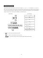
Listed below are the ”Default Configurations” and adjustable ranges by the “configuration” function:
Configuration items
Default configuration
Valid range
Non Retentive
M0~M799
M0~M1399
Retentive
M800~M1399
M0~M1399
Non Retentive
S0~S499
S20~S999
Retentive
S500~S999
S20~S999
0.01S
T0~T49
T0~T255
0.1S
T50~T199
T0~T255
1S
T200~T255
T0~T255
Retentive
C0~C139
C0~C199
Non Retentive
C140~C199
C0~C199
Retentive
C200~C239
C200~C255
Non Retentive
C240~C255
C200~C255
Retentive
R0~R2999
R0~R3839
Non Retentive
R3000~R3839
R0~R3839
Read-Only Register
0
R5000~R8071
High Speed Timer (0.1ms)
R4152~R4154
Unchangeable
High Speed Counter
0
HSC0~HSC7
External Interrupt
0
INT0~INT15
Station number
No.1
No.1~No.255
Internal Coil
M1400~M2001
are non retentive
Step points S0~S19
are fixed for non
Step Coil
Timer*
Remarks
retentive
16-Bit Counter
32-Bit Counter
Data Register
D0~D3171 are always
retentive
Remark 1: For the items marked with “*”, can only be modified while PLC is at initial state. After the program had written
to the PLC, changing of these two items is prohibited. The only way to change configurations after had written
a program into the PLC is to perform the system initial operation, which means you will lose all the programs
and get a defaulted configuration again. Please pay more attention on this.
Remark 2: The registers in the range of R5000~R8071 if not used for Read-Only registers, could be used as normal
read and write registers.
33
4.4.1
INTERNAL COIL PARTITION
【Key Sequence】
【LCD Display】
SYS
MODE
4
J
ENT
ENT
Input Non
Retentive No
ENT
4.4.2
STEP COIL PARTITION
【Key Sequence】
【LCD Display】
SYS
MODE
4
J
ENT
2
F
ENT
Input Non
Retentive No
ENT
34
4.4.3
0.01S~1S TIMER PARTITION
【Key Sequence】
【LCD Display】
SYS
MODE
4
J
ENT
3
G
ENT
Input the
0.01s timer
No.
ENT
or
Input the 0.1s
timer No.
ENT
y After setting the 0.01S and 0.1S timer
number, it is not necessary to set 1S
timer number
4.4.4
16-BIT COUNTER PARTITION
【Key Sequence】
SYS
4
J
ENT
4
I
【LCD Display】
ENT
Input the 16-bit
coynter No.
ENT
35
4.4.5
32-BIT COUNTER PARTITION
【Key Sequence】
SYS
MODE
4
J
ENT
5
J
ENT
4.4.6
【LCD Display】
Input the 32-bit
counter retentive
No.
ENT
DATA REGISTER PARTITION
【Key Sequence】
SYS
MODE
4
J
ENT
6
K
ENT
Input the
retenive No.
ENT
【LCD Display】
36
4.4.7
READ-ONLY REGISTER ASSIGNMENT
【Key Sequence】
【LCD Display】
SYS
MODE
4
J
ENT
7
4.4.8
N
ENT
Input the
read-only
register No
ENT
HSC/HST/INT ASSIGNMENT
8.HSC/HST/INT
ASSIGNMENT
_
HIGH SPEED TIMER
/COUNTER SELECT
HSC0/HST0 SELECT
0
(0:HSC,1:HST)
5
5
5
HSC0→_MD:2 K:X12
R:X13 M:X14 C:X15
5
5
5
HHSC CLOCK
POLAR
Please refer the chapter “High
speed counter/timer” of the
“advanced user’s manual”
5
5
5
HHSC CLEAR
POLAR
INTERRUPT ASSIGN
INT : X0+, X1-
5
5
5
Please refer the chapter “Interrupt”
of the “advanced user’s manual”
INT : X15+, X15-
FUN83
SPD:
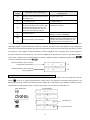
Remarks 1: There are 4 sets of hardware HSC0~3, and 4 sets of software HSC4~7 in FBs MC and MN models, but
only 2 sets of software HSC4 and HSC7 in MA model.
2: Counter MODE(MD)setting:0 means U/D, 1 means U/D×2 times precision, 2 means K/R, 3 means K/R×2
times precision, 4 means A/B phase, 5 means A/B phase×2 times precision, 6 means A/B phase×3 times
precision, 7 means A/B phase×4 times precision.
37
4.4.9
PSO0~3 SETTING
確認
9) PSO0~3 SETTING
CDEFINE Y0~7
PSO0(Y0,Y1)
(0)Y0=P,Y1=DIR:
PSO1(Y2,Y3)
(0)Y2=P,Y3=DIR:
PSO2(Y4,Y5)
(0)Y4=P,Y5=DIR:
PSO3(Y6,Y7)
(0)Y6=P,Y7=DIR:
PSO0(Y0,Y1)
(1)Y0=UP,Y1=DN:
PSO0(Y0,Y1)
(2)Y0=A,Y1=B :
PSO0(Y0,Y1)
(4)NOT USE :
PSO0(Y0,Y1)
(3)Y0 = PULSE :
PSO1(Y2,Y3)
(1)Y2=UP, Y3=DN:
PSO1(Y2,Y3)
(2)Y2=A,Y3=B :
PSO1(Y2,Y3)
(4)NOT USE :
PSO1(Y2,Y3)
(3)Y2 = PULSE :
PSO2(Y4,Y5)
(1)Y4=UP,Y5=DN:
PSO2(Y4,Y5)
(2)Y4=A,Y5=B :
PSO2(Y4,Y5)
(4)NOT USE :
PSO2(Y4,Y5)
(3)Y4 = PULSE :
PSO3(Y6,Y7)
(1)Y6=UP,Y7=DN:
PSO3(Y6,Y7)
(2)Y6=A,Y7=B :
PSO3(Y6,Y7)
(4)NOT USE :
PSO3(Y6,Y7)
(3)Y6 = PULSE :
※ Screens with a dotted line will be automatically cycled through
4.5
SYSTEM MESSAGE
【Key Sequence】
SYS
MODE
【LCD Display】
5
J
ENT
x
x
x
x
38
4.6
4.6.1
SETTING
SET PLC STATION NO.
【Key Sequence】
【LCD Display】
SYS
MODE
6
K
ENT
ENT
ENT
1
E
1
E
SHORT
0
OPEN
SHORT
ENT
y Specify whether to save
the PLC station No. to the
ladder section and to the
FBs-PACK
The FBs is factory default to 1, you can use this function to change the No. to between 1~255.
4.6.2
SELECT BAUD RATE OF PORT0~4
【Key Sequence】
SYS
MODE
6
K
ENT
2
【LCD Display】
F
ENT
Cyclic display
0~4
39
4.6.3
VOLUME
【Key Sequence】
SYS
MODE
6
K
x
x
ENT
3
【LCD Display】
G
ENT
OR
40
5
Operation of EDIT MODE
Fundamental key operations of edit mode:
n=1~8
1.
●
Execute
System mode has a total 7 functions: 1. EDIT PROGRAM
2. EDIT REGISTER DATA
3. SYNTAX CHECK
4. MOVE HR→ROR
5. CHECK DOUBLE COIL/T/C
6. EDIT HSPSO INSTRUCTION
7. EDIT LINK INSTRUCTION
8. EDIT DOCUMENT
●
When the first time enter the Edit Mode, the LCD screen will be automatically prompted with main function 1 which is
the “EDIT PROGRAM”. If it is not the desired function can either directly input the function number (n) or use
to search for the desired function and then press
5.1
to execute the function.
EDIT PROGRAM
Before start working on the following example, please perform the “CLEAR” operation shown in section 2.2.1 first.
●
Enter the edit mode
【Key Sequence】
【LCD Display】
(If want to enter the sub-program area, press
【Key Sequence】
.
Press
again will return to the main-program area.)
【LCD Display】
S: indicates the sub-program area
M: indicates the main program area
41
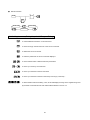
●
Instruction keys, parameter keys and
key are the basic keys used in the program Edit Mode. Besides that other
keys are also provided for searching, writing and correcting the programs.
: This key is used to select the main-program or sub-program area because the main-program and
sub-program are stored in different areas.
: This key is used to select the first or second row displayed on LCD. Using this key can move the cursor
to the row to be edited. In the program Edit Mode, this key is used to select the editing of the
instructions (second row on display) or their documents (first row on display).
: In the Edit Mode, edited information will not be saved in PLC until
is pressed. Before pressing
data are stored in a temporary editing area for subsequent checking and correcting.
,
can be used
to clear this temporary editing area. Once pressing this key, LCD screen will be cleared. With this key,
the wrong data or instruction in edit process can be cleared if
: After pressing
has not been pressed.
, instructions or data will be stored in the PLC program area. In this case,
not be used to clear them. Instead
can
is required to delete them from the program area of the PLC.
: This key is used to insert instructions in a program.
or
: These keys are used for program address increment or decrement.
: Move the cursor to the top(address:0000M or 0000S)of the main-program or sub-program.
: Move the cursor to the bottom(”BOTTOM” will be displayed on LCD)of the main-program or
sub-program.
: To choose the display or input in decimal format. (When enter EDIT mode for the first time, the display
will be in decimal).
: To choose the display or input in hexadecimal format.
●
The display format of mnemonic instruction
M
Address
Operand
0000M
Ladder Symbol
Instruction code
AAAAA Upper row document
BBBBB Lower row document
Main/sub program
Upper row Lower row
Program address
document document
Mnemonic instruction
Display format
Instruction code
Operand
42
←First row of LCD display
←Second row of LCD display
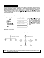
5.1.1
Sequential Instruction Editing
a ) Fundamental Key Operations of Sequential Instruction
● ORG instruction
1
Ö
OPEN
SHORT
2
NOT
TU
TD
X
Y
M
S
T
C
Operand
Operand
No..
No.
● LD instruction
1
Ö
OPEN
SHORT
2
NOT
TU
TD
X
Y
M
S
T
C
OOperand
perand
No.
No.
3
● AND instruction
1
Ö
OPEN
SHORT
2
NOT
TU
TD
X
Y
M
S
T
C
OOperand
perand
No.
No.
● OR instruction
1
Ö
OPEN
SHORT
2
NOT
TU
TD
X
Y
M
S
T
C
Ope
rand
Operand
No.
No.
43
● ANDLD instruction
Ö
● ORLD instruction
Ö
● OUT instruction
Ö
Y
M
S
● FO instruction
Ö
0~3
44
Operand
Operand
No.
No.
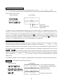
b ) Input the Instruction
X0
M1
Y2
【Key Sequence】
【LCD Display】
On pressing
, If the input is correct, the instruction will be written into the memory and the address shown on
the LCD display will change to the next location.
c ) Insert the Instruction
If want to insert a new instruction before an old instruction, first find the old instruction then type the new instruction
at the address of the old instruction and press
. The address of old instruction will move to the new location
right after the new instruction which means all the step number of the old instructions after the one inserted will be
increased by one. Continuing the example shown above, before inserting a B contact of X3 between the A contact
X0 and A contact M1, use
to find the step before which a new instruction is to be inserted (in this case
to complete the insert operation.
AND M 1 at step 0001M) and key in the instruction to be inserted then press
X0
M1
X0
Y2
X3
X3
【Key Sequence】
【LCD Display】
45
M1
Y2
d ) Change Instruction
First find the old instruction to be changed (if it is a function instruction, should step to the address which show FUNXX
of the instruction) then key in the new instruction and press ENT key to overwrite the old instruction. For example, if
you want to change Y2 to a retentive output coil and A contact X0 to TD down differential contact X1, find the old
instructions to be changed using
, then key in the new instruction or modify the instruction and press
to
complete the change as shown below.
X0
X3
M1
X0
Y2
【Key Sequence】
X3
M1
Y2
L
【LCD Display】
yFind out the instruction to be changed
(OUT Y2)
y Change OUT to OUT L
y Repeatedly pressing
4 times will
do the same thing
y Change A contact to TD contact and
change X0 to X1
e ) Delete Instruction
Find the instruction to be deleted. On pressing the
key, the instruction under display is deleted. The
example shown in below demonstrates how to delete the A contact M1.
X0
X3
M1
X0
Y2
L
【Key Sequence】
X3
【LCD Display】
46
Y2
L
f ) Edit the Element Documents
The element documents are the same for the instructions with identical operand number. For example, the element
comments of AND X0 and OR NOT X0 are actually the same as shown in the diagram below. The documents consist
of two rows of strings (5 characters for each row and a total of 10 characters) and place directly underneath the
element.
×△△△△
A1 A2 A3 A4 A5
B1 B2 B3 B4 B5
A and B rows shown in the diagram above occupy 10 characters space of the first row on the right side corner of
FP-08 LCD display.
A (upper) row document
0 0 0 0 M
B (lower) row document
A A A A A B B B B B
Example:Following the key operations shown in below to add the documents to TD contact X1.
X1
Y2
L
X3
0000M
SW
NO 1
【Key Sequence】
【LCD Display】
y
47
key moves the cursor to the
upper document area
y Cursor moves three characters
horizontally on pressing the
three times
5.1.2
Edit Function Instruction
In this section, we only concentrate on the key operations of editing the function instructions. For explanations of function
instructions, please refer to Chapter 6, “Introduction to function Instructions”.
Each function instruction consists of an instruction name (Mnemonic) and a reference number except nine special
instructions keys such as T, C, SET etc.. Besides those nine special instructions, other function instructions must be
entered with their function number (FUNXXX). It is possible to add a postfix character D and P after the FUNXX on certain
function instructions to produce sub-instructions. The key operations of function instructions are shown below.
Fundamental key operations of the function instructions
Input the FUN#
Input the parameters of operand
OPERAND
1
OPERAND
2
OPERAND
n
OPERAND
1
OPERAND
2
OPERAND
n
Continuing from the previous LCD display, input the function instructions listed below:
X2
0003M
CK
6D.BSHF
D : WY 16
Y3
OUT
X3
IN
ORG
X
2
LD
X
3
X
4
LD OPEN
LD
L/R
FUN
X4
D: WY
CLR
X5
EN
9DP.MOV/
S :
255
D : R
0
OUT
Y
3
ORG
X
5
FUN
9DP
D: R
48
16
FO
S:
2
6D
255
2
【Key Sequence】
【LCD Display】
to clear the incorrect instruction or parameters, then key in
Description: In case an error occurs during editing, press
the correct one and press
.
49
5.1.3
Search Program
In the process of editing, monitoring and searching the PLC program, it is very time consuming to search for the address
of a specific instruction using
operation using
if the size of the program is very large. FBs-PLC provides a program search
that gives you a convenient way to search through a long program for a specific instruction, address,
operand, comment or parameter.
Type
Items can be searched
Examples
Main-program (△△△△M)
0001M,0047M,······
Sub-program (△△△△S)
0007S,1234S,······
Address search
Instructions (either sequential instructions or
application instructions
ORG X0,OUT L Y2,FUN 20P,······
Parameters of function instructions
R100,WX0,T50,······
Element + Operand
TU X10,NOT M200,······
Operand
X0,M1000,······
Instruction document
SW1,AUTO STOP,······
Instruction search
Document search
Syntax chart of key operation of the program search
search for data without change
next searching
Input the data to
be searched
program change,
data move etc.
To search for a specific data in program memory, first require to input the data to be searched. The data have just
entered are stored in a search buffer. After pressing
, FP-08 will begin to search in the program memory of the PLC
for the specific data stored in the search buffer. The data stored in search buffer are retained even after completion of the
search operation. This means the consecutive data search and data change are possible. The data stored in search
buffer will be cleared in case of power failure or mode (Edit, Monitor, System, RUN/STOP etc.) change.
5.1.3.1
Search Address
To search for a specific address in program memory, input the address you wish to search first. The system will search
for that particular address in either main-program or sub-program area according to the input specification such as M
(main-program area) or S (sub-program area). Which means you can search for a particular address in the
sub-program area while working in the main-program area or vice versa. If found, the address will be displayed on
LCD otherwise the search will stop at the last address of the program area and “NOT FOUND” will be displayed.
50
Continuing from the preceding LCD display, if want to search for a particular address (0001S) in the sub-program area
while working in the main-program area (0011M), can perform the key operations shown below.
【Key Sequence】
【LCD Display】
y Press
once, “M” appears than
press this key again, “S” appears
y
y
y
The address is not found because the programs are not exist in the sub-program area. LCD display shows the
search is stopped at the last address (000S) of the sub-program area. If want to return to the main-program area,
perform the following key operations.
【Key Sequence】
【LCD Display】
5.1.3.2
Search Instruction
Instruction search is used to search for the specific instruction in the main/sub-program area. There are two ways can
be used to do the instruction search.
1. Input(or change)the instruction to be searched: FP-08 searches the data from the top of the program (0000M)to the
last address of the program including the sub-program area.
2. Using the data retained in the Search Buffer to perform the search operation: FP-08 searches the data starting from
the address next to the one displayed on LCD. Sub-program area is also been searched.
Input the instruction to be searched first, then press
. FP-08 will perform the search operation starting from the top
of the program. If found, the instruction will be displayed on LCD. To continuously search for the same instruction,
press
to resume the instruction search starting from the address next to the one of displayed. If
is pressed
continuously, all the addresses having the specified instruction are successively displayed until the address with “NOT
FOUND” is displayed. After the message “NOT FOUND” is displayed for 2 seconds, the address last found in the
program is displayed. In addition, it is also possible to use the search instruction to search the instruction with partial
specified (please refer to the table shown above to know the available specifies for instruction search).
51
●
Using the operand to search for “X3”
【Key Sequence】
【LCD Display】
y Found (first)
●
y Not Found (Only display 2 seconds)
Using the document to search for “SW NO1”
【Key Sequence】
【LCD Display】
y Use the
key to switch the
operating mode to document
search mode
Remark: The difference of the display between instruction/address search and document search is that a message
“DOCUMENT” is displayed on the right corner of the LCD screen when the document search is performed.
key can be used to select one of the two search methods.
52
●
Successive search and change
Following the preceding LCD display, search for all the instructions containing an operand X3 and then change the
operand X3 to X2.
【Key Sequence】
【LCD Display】
y Search buffer contains the old data from last
search operation (Document search)
y
y Key in the new data to be search (Operand X3)
key switches the mode from document
search to address/instruction search
y Found the second instruction containing an
operand X3
y Change operand X3 of the found second
instruction X2
y Found the first instruction containing an operand X3
y Change operand X3 of the first found instruction to
X2
`
Remark 1: In the process of successive search, if other keys other than the
parameter keys to change the operand data, you must press
Remark 2: As we have mentioned in above, a
key is pressed, such as pressing the
key again to resume the search process.
key must be pressed to resume the search process after a data
changing process. Users should keep in mind that the data stored in search buffer are retained during the
whole process. The resumed search will start from the current address displayed on LCD. But if you input a
new data to be searched at this time, search will automatically start from the top that means 0000M or 0000S.
53
5.2
EDIT REGISTER DATA
This function is provided mainly for editing (input) the data of the registers which number are consecutive. You must use
this function to edit the ROR data. It is possible to use the register editing function of monitor mode to change the
register’s value, but you need to repeatedly press
key for successive editing (please refer to the section 2.2.5). In
comparison, the method we provided in this section is more convenient to do so.
●
Key operations for entering the register data Edit Mode:
【Key Sequence】
【LCD Display】
After entering the register data edit mode, you can directly select the number of the registers(R△△△△,DR△△△△ or
the registers consist of 16 or 32 coils, such as WY△△△ and DWM△△△△ etc.)which you wish to edit. The table
shown in below listed the names of the registers which can be edited and the ranges of the corresponding register
numbers.
Register type
Number range
Remark
Data Registers
R0~R3839
Output Registers
R3904~R3967
HSC Registers
R4096~R4127
Calendar Registers
R4128~R4135
Special Registers*
R4136~R4167 及 R3967~R4095
as ROR could used as
Read-Only Registers
R5000~R8071
normal registers (R/W)
D△△△△
D Registers
D0~D3071
WY△△△
Output Coils
WY0,WY8,……WY144
WM△△△△
Internal Coils
WM0,WM8,……WM1384
WS△△△
Step Coils
WS0,WS8,……WS984
Data Registers
DR0~DR3838
Output Registers
DR3904~DR3966
HSC Registers
DR4096~DR4126
Calendar Registers
DR4128~DR4134
R△△△△
16
bits
DR△△△△
marked " * " (please refer
to page 3-4)
The rest of R5000~R8071
which are not configured
△△△△ or △△△must
be the multiples of 8
*: except the special register
Special Registers*
32
bits
*: except the special register
marked ”
DR4136~DR4166
and DR3968~DR4094
Read-Only Registers
DR5000~DR8070
DD△△△△
D Register
DD0~DD3070
DWY△△△
Output Coils
DWY0,DWY8,……DWY128
DWM△△△△
Internal Coils
DWM0,DWM8,……DWM1368
DWS△△△
Step Coils
DWS0,DWS8,……DWS968
54
△△△△ or △△△must
be the multiples of 8
Example 1
16-Bit register editing (assuming already in the register data Edit Mode)
R0=148
R1=72
R2=255 (or FFH)
【Key Sequence】
【LCD Display】
(before edit) of R0
y ×××××× is the current value
y After input a new value, the displayed
register number will be increased
successively.
●
After you entering the EDIT MODE of FP-08, the current value for registers starting with an R (R△△△△ or
DR△△△△) are displayed in decimal format, while for the registers starting with an W (W□△△△△ or DW□△△
△△), are displayed in hexadecimal format. Pressing
keys or
keys can change the format as you
desired.
●
If you want to change the current value of a register, key in the new value directly and then press
complete the change. If not simply press
key to display the next register.
55
key to
Example 2
32-Bit register edit
Continues from the Example 1, input 3H for registers R4~R5 and 73H for registers R6~R7.
【Key Sequence】
【LCD Display】
Example 3
The register number is increased
by 2 because DR occupies two
registers.
The editing of 32-Bit register composed by coils
Continues from the Example 2, input FH for register DWM8(M8~M39)and 15 for register DWM40(The value of FH is
equal to 15 while their input format are different).
【Key Sequence】
【LCD Display】
56
The address immediately after
the DWM8 is DWM40
5.3
SYNTAX CHECK
Every computer language has its own syntax rules to follow, otherwise the computer will not execute the instructions if
there is a syntax error existed in the program. Ladder Diagram program used by the PLC has its syntax rules as well.
Besides the syntax rules on designing of the Ladder Diagram program shown in Chapter 1, other syntax rules of FBs-PLC
are listed as follows.
1.
The maximum permissible element size in a Ladder Diagram network is 16 rows×11 columns. But this size can be
expanded to 16 rows×22 columns according to the specific needs (please refer to Figure 1 in page 1-5).
2.
Contacts such as A, B, TU, TD, SHORT and OPEN can be located on any columns except the last column (column
11 or column 22).
3.
Coils can only be located on the last column of the network (column 11 or column 22)
4.
The width of all application instructions in the Ladder Diagram occupies 3 columns and the length is variable
between 1~4 rows. Except the instructions listed in rule No.5 shown in below, the rest of the application instructions
must be located on column 2, 3 and 4 counting from the end (column 8, 9, 10 or column 19, 20, 21)
5.
Each of the six instructions, such as FUN 1(MCE), FUN 3(SKPE), FUN 65(LBL), FUN 68(RTS), FUN 69(RTI), FUN
70(FOR), and FUN 71(NEXT), forms its own network. No other elements can be serially connected in front of these
instructions; that is, these instructions are connected directly to the original line and occupy the first three columns
(column 1, 2, 3). These instructions do not have the output function either and the instruction FUN68 and FUN69
can only be used in the sub-program area.
6.
For each multiple-input instructions, every input point needs a serially connected element; that is, every FUN
instructions with n inputs must have n numbers of network rows connecting to each input point.
7.
Instructions FO# can only be used with the application instructions containing the function output (FO). Following
every FO# instruction, there must be a corresponding OUT instruction.
8.
Six instructions such as FUN 0(MC), FUN 2(SKP), FUN 66(JMP), FUN 67(CALL), FUN 70(FOR) and FUN 71(NEXT)
which are used for controlling the program flow can only be located on the first column of the network and can not
be connected to OUT or any other application instructions in parallel starting from row 2.
9.
The ladder diagram is illegal if it has following condition.
(1) Cross a line
(2) FUNs with input overlap
10. The instructing combinations, which can not form the diagram, are not permissible.
(1) The contact element occupies the location of the coils and application instructions.
(2) If there are several OUT TR# instructions in a single network, when you want to get the TR statuses(LD TR#)
from the memory, you should first get the TR# contact which stored at the last.
11. The name of LBL must be unique in the program.
12. The # of MC or SKP instruction can not be duplicated.
13. The # of TR can not be duplicated in the same network.
14. The number of the instructions in a network can not exceed 64 Words.
15. The number of instructions resulted from subtracting the total number of ORLD and ANDLD instructions from the
total number of LD instructions can not exceed 8 for any combination of the instructions in a network. If the network
including the OUT or application instructions, then the subtraction between number of the LD instructions and
number of the ORLD+ANDLD instructions need to be recalculated.
57
5.3.1
Key Operations of Syntax Check
【Key Sequence】
【LCD Display】
The STEP indicates where
the error occurs
↓
↑
Error code
5.3.2
Syntax Error List
ERROR 1 : Instruction ORG is missing
ERROR 2 : AND, OR, LD, ORLD, ANDLD, OUT TR, FUN, C and T instructions can not be connected directly after the
FUN and C instructions.
ERROR 3 : OR, ORLD, ANDLD and OUT TR instructions can not be connected directly after the OUT and T instruction.
ERROR 4 : OR, ORLD, ANDLD and OUT TR instructions can not be connected directly after the OUT TR instruction.
ERROR 5 : OR, ORLD, ANDLD and OUT TR instructions can not be connected directly after the LD TR instruction.
ERROR 6 : FUN instruction does not exist before the FO# instruction.
ERROR 7 : The # of FO# exceeds the limit.
ERROR 8 : The # of FO# can not be duplicated.
ERROR 9 : FO instruction can only connect one OUT instruction.
ERROR 10: FO instruction does not exist before the OUT instruction.
ERROR 11: In a network, OUT, FUN, T and C instructions can not be used after the MC, SKP, JMP, CALL, FOR and
NEXT instructions.
ERROR 12: In a network, the # of OUT TR# has been repeatedly used.
ERROR 13: In a network, LD TR# is used without the OUT TR#.
ERROR 14: In a network, the number of the instructions resulted from LD+LD TR−ORLD−ANDLD is greater than 8 (If
FUN or C instructions are appeared, the number need to be recalculated).
ERROR 15: After the LD instruction, its pairing instructions of ORLD and ANDLD can not be found.
ERROR 16: ANDLD instruction can not be used in pairs following a LD TR instruction.
58
ERROR 17: Before the ORLD instruction, its pairing instructions of LD and LD TR can not be found.
ERROR 18: Before the ANDLD instruction, its pairing instruction of LD can not be found.
ERROR 19: OUT, OUT TR and LD TR instructions are used prior the completion of the block editing.
ERROR 20: There are not enough LD or LD TR instructions available to match the input numbers of the FUN and C
instructions.
ERROR 21: In forming the Ladder Diagram, the network exceeds 16 rows.
ERROR 22: In forming the Ladder Diagram, the contacts occupy the coil location.
ERROR 23: In forming the Ladder Diagram, the contacts occupy the location of application instruction.
ERROR 24: In forming the Ladder Diagram, MC, SKP, JMP, CALL, FOR and NEXT are not located on the first row.
ERROR 25: In forming the Ladder Diagram, the input contact location of FUN and C exceeds the limit of allowable input
contact paths.
ERROR 26: In forming the Ladder Diagram, either two of the FUN and C input contact paths are touching or stacking to
each other.
ERROR 27: In forming the Ladder Diagram, there is a vertical short circuit line contacting the edges of the application
instruction.
ERROR 28: In forming the Ladder Diagram, you must use the ORLD and OR instructions to connect the contacts in the
preset OUT TR# diagram.
ERROR 29: In forming the Ladder Diagram, ORLD instruction can not form a reasonable diagram.
ERROR 30: In forming the Ladder Diagram, LD TR instruction can only be used to form the diagram in forward direction.
ERROR 31: In forming the Ladder Diagram, LD TR instruction can cause the line-cross problem.
ERROR 32: In a program, the # of MC# and MCE# are duplicated.
ERROR 33: In a program, the # of SKP# and SKPE# are duplicated.
ERROR 34: In a program, the # of T# is duplicated.
ERROR 35: In a program, the # of C# is duplicated.
ERROR 36: The number of the instructions in a network exceeds 64 words.
59
5.4
MOVE (HR→ROR)
This function is provided mainly for moving the contents of the data registers (HR) to read-only registers (ROR) area so
that it can be burned into EPROM or EEPROM.
【Key Sequence】
【LCD Display】
y Move the data of R0~R9 to R5000~
R5009, and the data of R0~R9 will
not be changed.
y This will not appear if the range of
read only registers larger than R5008
5.5
CHECK DOUBLE COIL/T/C
This function is provided mainly for checking Coil, Timer, Counter, if they are used more than once in the program. After
executing, if it found, will display the double coil number.
【Key Sequence】
【LCD Display】
60
y In this case T1, Y10, Y12, Y20, and
Y22 are double used.
5.6
EDIT HSPSO INSTRUCTION
There are some unique control instructions especially provided by FBS-PLC for NC positioning. The users need only to
choose the starting register (R0~R3828, R5000~R8060, D0~D3060) where these instructions are stored, then FP-08
will judge automatically on whether the number selected is a new or an old HSPSO instruction area. The basic unit of
or
HSPSO instructions is a command. A complete command consists of 3-4 instructions. Press
or decrease the number of command. Press one of
,
,
or
key to increase
key to leave and save the editing, then follow
the guide displayed on FP-08.
●
Start HSPSO instruction editing
【Key Sequence】
【LCD Display】
※Press
start
and
HSPSO
keys may also
instruction
editing
when “FUN 140” is displayed in the
editing
ladder
Press
and
instruction
area.
keys again to
return to “FUN 140” for instruction
editing.
●
Formation of a NC command
1. Continuous multi-zone speed
2. Last or single zone speed
SPD (speed)
SPD (speed)
DRVC (pulse numbers or distance)
GOTO
END
GOTO
NEXT
(end)
(to next set)
DRV (pulse numbers or distance)
GOTO
WAIT
ACT
EXT
MEND
XXX
(to the nth set)
(wait after
finish)
(wait in
acting)
(wait for triggering
in acting)
(end)
GOTO
END
GOTO
NEXT
GOTO
(end)
(to next set)
(to the nth set)
XXX
Remark: DRVC is used for performing continuous multi-zone speed changing control (up to 8 commands) and the last
command must apply DRV instruction.
61
5.6.1
●
Fundamental Key Process of HSPSO Instruction
SPD instruction
SPD
0 ~9
R
D
●
DRVC、DRV instruction
DRV XXX
DRVC XXX
+
CLR
R
D
+
0 ~9
CLR
●
DRV ADR (Ut)
DRV ADR (Ps)
DRV ABS (Ut)
DRV ABS (Ps)
DRVC ABS (Ps)
DRVC ABS (Ut)
DRVC ADR (Ps)
DRVC ADR (Ut)
WAIT、ACT、EXT、MEND instruction
WAIT
0 ~9
R
D
X
Y
M
S
0 ~9
R
D
X,Y
M,S
EXT
0 ~9
WAIT
ACT
MEND
EXT
62
●
GOTO instruction
GOTO
0 ~9
R
D
GOTO END
GOTO NEXT
GOTO xxx
5.6.2
Supplementary Editing Keys for NC Program Editing
: To switch different instructions on the same level.
: To insert an empty command in front of the current command.
: To delete the current command.
: To reset the parameters of current command displayed.
,
or
: To move between DRV or DRVC instruction parameters.
: To move up or down by one instruction.
: To move up to the SPD of the first command.
: To move up to the SPD of the last command (a new empty command).。
: To leave HSPSO instruction editing. Then, FP-08 will display the range in the register being used
by the whole commands and the user will be asked whether to save or not.
63
5.6.3 Editing Example
【Key Sequence】
【LCD Display】
y "" : Indicating the first
set.
"" : Indicating the set has
not been input completely.
64
y Save the edited command to
(R0~R19)
5.7
EDIT LINK INSTRUCTION
There are two unique LINK functions provided by FBS-PLC for PLC networking. The LINK function is driven by the LINK
instructions which are stored in the data registers. The users need only to input the starting register of the area which
used to store the instructions for the link function, and then FP-08 can automatically distinguish if this area is for new
entry or for editing. A LINK instruction consists of 4-5 fields of data. Once a new instruction is complete, FP-08 will store
this instruction with 1 set of communication data into the data area. Press
instruction. Press one of
●
,
,
or
or
to insert or delete 1 set of LINK
to leave and save the editing, then follow the guide displayed on FP-08.
LINK Instruction Editing
【Key Sequence】
【LCD Display】
※ Press
instruction
editing
when
“FUN
96/97” is displayed in the editing
ladder instruction area. Press
●
may also start LINK
again to return to "FUN 96/97"
for ladder instruction editing.
y Unless for testing, the TOTAL SETS
input need not to enter since FP-08
will automatically update this number
according to the total set of
instructions being entered.
The construction of the LINK instruction
STATION NO.
COMMAND
READ
WRITE
GET STATUS
Remark 1: Use
H-LINK
to select one of the
four types link COMMAND.
Remark 2: DATA LENGTH: 1~64
Remark 3: The available parameters for
DATA LENGTH
DATA LENGTH
DATA LENGTH
MASTER/SLAVE START
include X, Y, M, S, T, C, MX,
MASTER START
MASTER START
START
SLAVE START
5.7.1
Supplementary Editing Keys
65
WY, WS, TR, CR, R and D.
Please refer to the supplementary editing keys for HSPSO in section 2.5.6.2.
5.7.2
Editing Example
【Key Sequence】
【LCD Display】
y A new instruction data area. No need to change
this, Its value will be changed automatically
while the new instruction set is added.
y "": Indicating the first record
〝〞: Indicating the record has not been input
completely.
y The valid data length is 1~64. If the initial data
is not within this range, 〝〞 will be displayed
at the lower left-hand corner.
y Read data from R10~R15 of the slave station
(No. 2) and save them in R0~R5 of the master
station
y FP-08 automatically set it to 1, indicating that
there is one set of instruction in this data area.
66
y Save the edited instruction sets to (D0~D7).
5.8
EDIT DOCUMENT
This function provides the opportunity to add document for digital(X、Y、M、S、T、C)and register(R、D、WX、WY、
WM、WS)with 16 characters ( Only support 10 characters while at instruction edit mode). Instead of showing reference
number, all documented reference numbers will be shown by its document when displayed in FP-08 or WinProladder. If
properly use this function, will increase the readability of your ladder program.
【Key press】
【LCD screen】
EDIT
MODE
ENT
R
ENT
R
E
R
E
G
I
S
T
ENT
※
Key:Clear document while edit the document
Key:Move the cursor between first and second row
Key:Move the cursor right or left one character position while edit the document
67
6
The Operation of MONITOR MODE
There are two main operation functions available for MONITOR MODE.
1. STATUS/DATA MONITORING
2. PROGRAM MONITORING
Fundamental key operations of MONITOR MODE
n=1: STATUS/DATA MONITORING
n=2: PROGRAM MONITORING
1.
Execution of selected
operation
6.1
STATUS/DATA MONITORING
This operation is used to monitor the digital status and register data. Forcing operation can be used in this mode to
change the digital status and register data. In addition, digital element enable and disable control are also possible. The
key operations for entering the "STATUS/DATA MONITORING" function and the corresponding LCD display is shown
below.
【Key Sequence】
【LCD display】
●
●
"" letter on the LCD screen indicates current operation mode is STATUS/DATA MONITORING mode.
The arrow "" on the LCD screen prompts user to enter the digital or register reference number and then the status
will be displayed on the row where the arrow is stay. Using the
68
key to switch the arrow between these two rows.
6.1.1
Digital Status Monitoring
This function allows you to monitor the statuses of all digital points, such as X△△△, Y△△△, M△△△△ and
S△△△, If you want to monitor the status of a digital point after entering the STATUS/DATA MONITORING mode, follow
the key operations shown below.
【Key Sequence】
【LCD Display】
Digital Status
Enable /Disable status
Digital number
The ability of forcing or enable/disable the digital status is the auxiliary function of the digital status monitor function.
Therefore if you want to execute the force or enable/disable functions, it is required to monitor the digital status first. As
shown in the above diagram, the enable/disable status is displayed as well while you are monitoring the digital status. At
this time, you can enable or disable the digital by pressing the
key. A specific function (Enable or Disable) can be
selected by pressing the key alternately. The digital status can be forced to 1 or 0 by pressing the
key. Please refer
to section 2.2.4 for detailed descriptions on force and enable/disable of the digital status.
6.1.2
Register Data Monitoring
While monitoring the register data, the display data can be in decimal or hexadecimal format. FP-08 base on the register
type will automatically arrange the display format. Registers consisting of 16 or 32 bits (W□△△△△, DW□△△△△) are
displayed in hexadecimal format, with this format can easily to know the status of individual bits of register’s data. Since
those registers are bit oriented in application. The other register’s data are displayed in decimal format. Also can use the
or
keys to change the display format as desired. After change the display format of certain type of
register, all the register of that type will all display with the same format unless the monitoring register type is changed
such as changing R△△△△ to W□△△△△ or vice versa, or simply use the keys described above to change the
display format.
In the following example, we use the R registers and digital register to demonstrate the operation of register data monitor.
Example 1
16-Bit digital points register data monitoring
【Key Sequence】
【LCD Display】
69
y Value is displayed in hexadecimal
format because the register WM0 is a
digital points register
y Set the WM0 to 1000H
y Changes to decimal format
Example 2
32-bit register status monitoring
The data of the 32-bit registers (DR△△△△, C200~C255 and DW□△△△△) may be up to 11 digits including the sign.
Therefore a single LCD screen can only display one register data at a time. While display a 32-bit register, after pressing
the
key, FP-08 will automatically display the register number and contact status (if it is a counter register) at first row,
and the register data will be displayed in second row as shown in the below.
【Key Sequence】
【LCD Display】
The contact status of C200
The current value of C200
6.1.3 Change the Register Data
The register data displayed on the LCD screen can be changed as shown in example 1 where the data of WM0 is set to
1000H. However, the disable operation on register does not provide. Please refer to section 2.2.5 for more detailed
explanations. To change the register data, besides by entering the register data monitor mode, using the register data
edit function is a more convenient way. Please refer to section 2.5.2 for more explanations.
6.2
PROGRAM MONITORING
The PROGRAM MONITORING function can observe and check the program instructions either the PLC is at RUN or
STOP state. If the displayed instruction is a contact element, then FP-08 will display the conducting status and
enable/disable status of corresponding element. At the same time it can also perform the forcing or enable/disable
operation on that digital element. The key operations are similar to the ones shown in the status monitor function. Under
the PROGRAM MONITORING mode can also use the search function to find the desired instruction for monitoring. Key
operations of entering the PROGRAM MONITORING mode and the LCD displays are shown below.
【Key Sequence】
【LCD Display】
The contact status of NOT X3
element is conducting ("1")
The X3 is enable
Remark: The digital status shown in the STATUS/DATA MONITORING function is the status of the digital numbers such
as X0, Y0 etc, while the digital status shown in the PROGRAM MONITORING function is the conducting state of
the digital elements such as NOT X0, TU Y0 etc. The status of X3 in the data monitor mode is 0 as shown in the
example 1. But the status of the element NOT X3 in the program monitor mode is 1 as shown in the example
above. This is due to the fact that X3 status is 0, but the conducting status of B contact of X3 is 1. The
conducting status can only be retained for a single scan time for differential up and differential down contacts.
For that contacts the conducting status may not be observed unless at the same moment the data is happen to
read and displayed.
70
●
After entering the PROGRAM MONITORING mode, can also to perform the force and enable/disable operation
directly on relay and contact instructions. Please refer to section 2.2.4 for key operations.
●
The operation procedures for functions such as program browse and program search in the MONITOR MODE are
similar to those operation procedures in the EDIT MODE. The only difference is that the data can only be observed in
the MONITOR MODE while it can be edited in the EDIT MODE.
7 PLC Run/Stop Control
Fundamental key operations
After pressing the keystrokes as shown at left, will toggle the executing
state of the PLC. Which means if the PLC is at STOP state then it will
change to RUN state, and vice versa.
●
The key operations for the case of changing the PLC from STOP to RUN.
【Key Sequence】
【LCD Display】
Message "RUN" blinks which
indicates the PLC is running.
●
The key operations for the case of changing the PLC from RUN to STOP.
【Key Sequence】
【LCD Display】
71