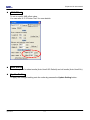
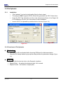
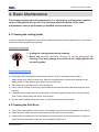
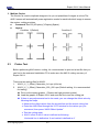
1
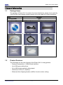
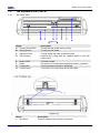
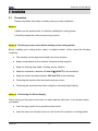
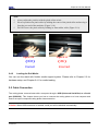
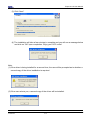
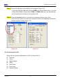
EXPERT 24 LX CUTTING PLOTTER User Manual ` Great Computer Corporation © NOTICE GCC reserves the right to modify the information contained in this user manual at any time without prior notice; un-authorized modification, copying distribution or display is prohibited. All comments, queries or suggestions concerning this manual please consult with your local dealer. Expert 24 LX user manual Important Information Thank you for purchasing the Expert 24 LX Cutting Plotter. Before you use the cutting plotter, please make sure that you have read the safety precautions and instructions below. ! Caution ¾ SAFETY PRECAUTIONS! For safety concern, please always hold the cutter firmly from the bottom while moving it. Do not move the cutter by clasping the depression area on both sides. O (correct) X (Incorrect) ¾ Do not shake or drop the blade holder, a blade tip can fly out. ¾ During an operation, do not touch any of the moving parts of this machine (such as the carriage). Also be careful to make sure that clothing and hair do not get caught. ¾ ¾ Always connect the power cable to a grounded outlet. Always use the accessory power cable which is provided. Do not wire the power cable so that it becomes bent or caught between objects. ¾ Do not connect the power cable to branching outlet to which other machines are also connected, or use an extension cable. There is danger of overheating and of mis-operation of the machine. ¾ Keep the tools away from children where they can reach. ¾ Always put the pinch rollers within the white marks. Important Information Expert 24 LX user manual Table of Contents Important Information 1. General Information 1.1 Package Items 1.2 Product Features 1.3 The Appearance 2. Installation 2.1 Precaution 2.2 Stand Installation 2.3 Blade Installation 2.4 Media Loading 2.5 Cable Connections 2.5.1 USB Interface 2.5.2 How to switch the USB mode 2.5.3 RS-232 Interface 3.Operation 3.1 3.2 3.3 3.4 The Control Panel VLCD File Uploader Data Transmission 4. Basic Maintenance 4.1 Cleaning the cutting Plotter 4.2 Cleaning the Grid Drum 4.3 Cleaning the Pinch Rollers 1-1 1-1 1-2 2-1 2-2 2-5 2-7 2-9 2-10 2-13 2-13 3-1 3-2 3-6 3-7 4-1 4-1 4-2 5. Accu-Aligning System 5.1 Introduction 5.2 Calibrating the System 5.2.1 Media Calibration 5.2.2 AAS Calibration 5.2.3 AAS II on Expert 24 LX 5.3 Printer Test 5.4 Contour Cutting 5.5 Tips for AAS 5-2 5-2 5-3 5-4 5-6 5-8 6. Trouble Shooting 6.1 What if Expert 24 cannot Operate? 6.2 Light Indicators 6.3 Cutting Quality Problems 6-1 6-1 6-4 5-1 Appendix A-1 Expert 24 LX Specification A-2 Blade Specification A-3 CorelDRAW Plug-In Instruction Table of Contents A-1 A-2 A-3 Expert 24 LX user manual A-4 GreatCut Instruction Table of Contents A-4 Expert 24 LX user manual 1. General Information 1.1 Package Items The package of Expert 24 LX contents the items listed below, please check carefully. If you find any item missing, please consult your local dealer for further assistance. 1.2 Item Cutting Plotter Accessories 1. Installation CD 2. AC Power Cord 4. Cutting Pad 5. USB Cable 7. Tweezers 8. Paper Slicer Quantity 1 Set 1 Set 3. Desktop Support Brackets 6. RS-232 Cable Product Features The followings are the main features of the Expert 24 LX cutting plotters: ‧ Dual-port connectivity – USB & Serial interface. ‧ Up to 250 gram cutting force. ‧ Up to 400 mm/per second cutting speed. ‧ Guaranty 3 meter (10’) tracking. ‧ Enhanced Accu-Aligning System (AAS II) for auto contour cutting. General Information 1-1 Expert 24 LX user manual 1.3 The Appearance (EX-24 LX) 1.3.1 The Front View A B C D E F G H 【Figure 1-1】 Object A Primary Pinch Roller B Slicing Groove C Alignment Ruler D Tool Carriage E F G H Blade Holder Platen Cutting Pad Control Panel Object J Grid Drum General Information Description To help hold the media during cutting. To help slice off media. To align media with clear guideline marks Performs the cutting with the installed blade or pen with AAS module. To hold the blade. The surface for holding and supporting media in operation. To protect blade and plate in operation. To consist of 10 control keys and 6 LED lights. Description To move media back and forth in operation. 1-2 Expert 24 LX user manual 1.3.3 The Side Views K L M N 【Figure 1-3】 Object K AC Power Connector L Fuse M Power Switch N USB Connector O Serial Interface Connector General Information O 【Figure 1-4】 Description To insert the AC power cord. 3Amp. To turn on or off the machine. To connect the machine and a computer through a USB cable. To connect the machine and a computer through a RS-232 cable. 1-3 Expert 24 LX User Manual 2. Installation 2.1 Precaution Please read below information carefully before you start installation. Notice 1 z Make sure the power switch is off before installing the cutting plotter. z Carefully handle the cutter to prevent any injuries. Notice 2 Choosing a proper place before setting up the cutting plotter Before installing your cutting plotter, select a suitable location, which meets the following conditions. z The machine can be approached easily from any direction. z Keep enough space for the machine, accessories and supplies. z Keep the working area stable, avoiding severe vibration. z Keep the temperature between 15 and 30℃ (60-86oF) in the workshop. z Keep the relative humidity between 25% and 75% in the workshop. z Protecting the machine from dust and strong air current. z Preventing the machine from direct sunlight or extremely bright lighting. Notice 3 Connecting the Power Supply Check the plug of the power cord to see if it mates with the wall outlet. If not, please contact your dealer. z Insert the plug (male) into a grounded power outlet. z Insert the other end (female) of power cord into the AC connector of cutting plotter. Installation 2-1 Expert 24 LX User Manual 2.2 Stand Installation 2.2.1 Stand Installation Please follow the procedures below for assembling the stand. Step 1 Please examine the supplied items in the accessory box of the stand carton before you install: Stand is an optional item for Expert 24 LX, Item List: z z z z z z z z z z 1 Left side vertical stand 1 Right side vertical stand 1 Support for left side 1 Support for right side 1 Stand Beam 2 Bottom Stands with wheels 2 Sliding brackets for paper take up 1 Hex Wrench (M5)Φ4 28 Socket flat head screws(M6*12L) 1 Installation Guide Step 2 Position the Left side vertical stand perpendicularly to part Xand put the screws into the holes and tighten them to form a left side T-stand (Figure 2-1). Repeat the same steps with the Right side vertical stand. Left side vertical stand X Bottom Stand Figure 2-1 Installation 2-2 Expert 24 LX User Manual Step 3 Place the stand beam upright on the T-stand and put the screws into the holes but do not tighten them at this step. Stand Beam T-stand Figure 2-2 Step 4 Position both the left Support and right Support perpendicularly to the T-stand and put the screws into the holes and tighten them as shown in Figure 2-3. Support for left side Support for right side Figure 2-3 Installation 2-3 Expert 24 LX User Manual Step 5 Remove the cutting plotter from the carton. Position the stand under the plotter, and insert the screws into the holes on the bottom of the plotter but do not tighten them up as shown in Figure 2-4. Figure 2-4 Step 6 Tighten the screws of step 3 and step 5. Place the sliding brackets for paper takeup onto the stand beam. sliding brackets for paper takeup Figure 2-5 Installation 2-4 Expert 24 LX User Manual 2.3 Blade Installation Figure 2-6 is the illustrator of the blade Adjustment depth knob holder. Insert a blade into the bottom of the blade holder and remove the blade by pushing the pin. Make sure that your fingers Outward ring are away from the blade tip. Pin Figure 2-6 Step 2 Push the blade to the bottom of the blade holder (Figure 2-8). Step 1 Install blade (Figure 2-7). Figure 2-7 Figure 2-8 Step 3 Adjust the blade tip to suitable length by screwing “Blade tip adjustment screw” clockwise or count-clockwise. (Figure 2-9). Figure 2-9 Installation Tips: “The proper length” means the blade’s length is adjusted 0.1mm more than film’s thickness. That is, if the thickness of film is 0.5mm, then blade’s length is properly adjusted 0.6mm and it can completely cut through the film layer yet avoid penetrating the backing. 2-5 Expert 24 LX User Manual Step 4 Insert the blade holder into tool carriage. Please note the outward ring of the holder must put into the grooves of carriage firmly (see Figure 2-10), fasten the case (Figure 2-11). Figure 2-10 Figure 2-11 Step 5 Use the reversing steps to remove the blade holder. Step 6 Eject the blade: Push “Blade eject pin” to eject blade when the blade needs to be replaced. Caution The blade will lose its sharpness after a period of usage, the cutting quality m be affected. By increasing the cutting force, it might do the trick. However, the blade is worn out and no longer provides a reliable cutting, you should rep a new one. The blade is consumable and must be replaced as often as neces to maintain the cutting quality. The quality of the blade deeply affects cu quality. So be sure to use a high quality blade to ensure good cutting results. Tips - When to replace a new blade: 9 If the blade is broken, you have to replace a new one. 9 If cutting quality is not as good as usual, you may need to replace a new one. 9 If the material cannot be cut through by higher cutting force, you may need to replace a new one. Installation 2-6 Expert 24 LX User Manual 2.4 Media Loading 2.4.1 Loading the Sheet Media To load the media properly, please follow the procedures below: Step 1 Lift the 2 levers at the back side of the cutter to lift the pinch rollers (Figure 2-12). Figure 2-12 Step 2 Load your media on the platen and slide it under the pinch rollers from either the front side or the backside. The alignment rulers on the platen extension will help you to adjust the media precisely (Figure 2-13). Figure 2-13 Step 3 Then move the pinch rollers manually to the proper position. Be sure the pinch rollers must be positioned above the grid drum. The stickers on the main beam show the position of the grid drums (Figure 2-14). The position of the first grid drum is indicated by a yellow and white sticker. Please note that the position of the 1st AAS registration mark should not be located within the area indicated by the yellowish part of the sticker. If the registration mark is located in the yellowish part of the sticker then the registration mark will fail to be detected. Figure re 2-15 Stickers Figure 2-14 Installation 2-7 Expert 24 LX User Manual CAUTION!!! 9 Make sure the Pinch Rollers are set to right positions. 9 Position the Pinch Rollers at the right and left sides of media. (O) Correct Figure 2-16 Pinch Roller (X) Incorrect Figure 2-17 Step 4 Push the lever backward to lower down the pinch rollers (Figure 2-15). Step 5 After turn on the power, the tool carriage will measure the size of the media automatically. And the plotting cutter begins to work. Installation 2-8 Expert 24 LX User Manual Note: 9 Always adjust the position with the pinch rollers raised. 9 Please reposition the pinch roller by holding the center of the pinch roller and moving it from the rear end of the machine. (Figure 2-18) 9 DO NOT move the pinch roller by holding its front rubber roller (Figure 2-19). Figure 2-18 Figure 2-19 (O) (X) Correct Incorrect 2.4.2 Loading the Roll Media You can use the stand with flexible media support system. Please refer to Chapter 2.2 for hardware setup, and Chapter 2.4.1 for media loading. 2.5 Cable Connection The cutting plotter communicates with a computer through a USB (Universal Serial Bus) or a Serial port (RS-232C). This chapter shows you how to connect the cutting plotter to a host computer and how to set up the computer/cutting plotter interconnection. !! Notice: When USB connection is enabled, serial port will be disabled automatically. Installation 2-9 Expert 24 LX User Manual 2.5.1 USB Interface Expert 24 LX build-in USB interface are based on the Universal Serial Bus Specifications Revision 1.1. (Operation system of Windows 95, Windows NT don’t support USB ). USB driver installation Caution!! 9 If you are using Windows 2000 / XP / Vista / 7 as your operating system, make sure you log in using the “Administrator” account. Use the USB One-click Installation for quick driver installation. Follow the simple steps below for driver setup. Step 1: Connecting your GCC cutter 1. Connect the USB connector to the machine and then USB driver will installed automatically. NOTE Check that the USB mode option is set to Common USB Mode before running the installation. Step 2: Installing the software (1) Put the installation CD into your CD-ROM. Please make sure that the USB device is connected before you start the driver installation. Installation 2-10 Expert 24 LX User Manual (2) Choose the model you want to install from the driver list and click on either the 32 bit or 64 bit driver installation depending on the operating system installed on your computer to start the installation. (The Expert Pro model is used as an illustration in the following steps.) NOTE If you use the Windows 7 / Vista 64 bit program, please note that a pop-up window will be shown upon the initial installation as shown below: Click “Yes” to continue. Installation 2-11 Expert 24 LX User Manual (3) Click “Next” (4) The installation will take a few minutes to complete and you will see a message below and click on “OK” upon completion. Enjoy your GCC cutter! Note: (1) If the driver is being installed for a second time, the user will be prompted as to whether a second copy of the driver installation is required. (2) If the user selects yes, a second copy of the driver will be installed. Installation 2-12 Expert 24 LX User Manual 2.5.2 How to switch the USB mode? Step 1. Press ON/Offline button to switch to the “offline” status. Step 2. Press “Pause” and “Origin Set” button at the same time and you will find the current status of the USB mode indicated by the three LEDs as shown below. ◎ Flashing ● LED on Operation System Common USB Mode GCC USB Mode Repeat Data Clear Cut Test ● ● ● ◎ ◎ ● A. 【Switching to GCC USB mode】 If you want to switch the USB mode from Common USB mode to GCC USB mode, please press the “Data Clear” button and then press the “origin set” button to finish your set up. B. 【Switching to Common USB mode】 If you want to switch the USB mode from GCC USB mode to Common USB mode, please press the “Cut Test” button and then press the “origin set” button to finish your set up. Step 3. Please re-connect the USB cable and complete the installation. 2.5.3 RS-232 Interface Connecting to the RS-232 (Serial) Port 1. For IBM PC, PS/2 users or compatibles, connect the RS-232C cable to the serial connector of the assigned serial port (COM1 or COM2) of your host computer. 2. Set up the communication parameters (Baud Rate and Data Bits/Parity) to match the setting of software package, refer to chapter 3 – “Misc” key description. Installation 2-13 Expert 24 LX user manual 3. Operation 3.1 The Control Panel 3.1.1 The Outline of control panel Figure 3-1 Key Function POWER LED To indicate the power status ( light up: power on; light off: power off ) ERROR LED To indicate the error status ( light up: error; light off: normal ) To switch modes or stop cutting job( light up: on-line; light off: off-line ) ON/OFF LINE While in on-line mode: only ON/OFF LINE and PAUSE keys activated While in off-line mode: the settings in VLCD can be adjusted. PAUSE To temporarily halt cutting process or to continue REPEAT To repeat last job. DATA CLEAR To clear up buffer memory. CUT TEST To perform cutting tests in different ways. ORIGIN SET To reset origin at a new position. 4 Arrow Keys To move carriage position, select function, or change setting. 3.1.2 Reset Origin Note: 9 Make sure the machine is in off-line mode to enable this function. Step 1 Move the carriage to a new position. Step 2 Press the ORIGIN SET button to reset origin. Operation 3-1 Expert 24 LX user manual 3.1.3 Cut Test Note: 9 Make sure the machine is in off-line mode to enable this function. 9 It’s recommended to keep performing this function until the cutting quality meets your demand before executing the cutting job. Step 1 After sizing, press the ON/OFF LINE button to set as off-line mode. Step 2 Move the carriage to a preferred position. Step 3 Press CUT TEST button to perform. 3.1.4 Repeat Note: 9 Make sure the machine is in off-line mode to enable this function. Step 1 Press the ON/OFF LINE button to set as off-line mode. Step 2 Press the REPEAT button to perform re-plot function starting at the position where the carriage locates. It is also available to move carriage to a preferred position, re-set origin, and then perform this function. 3.2 VLCD “VLCD” is a computer program to help modify parameters of cutting functions. 3.2.1 Installation Step 1 Copy the VLCD.exe file in the Accessories folder of the Expert 24 LX Installation CD onto your local drive to finish installation. Step 2 Launch VLCD by double-click on the icon. Note: Operation 9 Make sure the machine is in on-line mode to enable this program. 9 There is media in the machine. 3-2 Expert 24 LX user manual Step 3 Choose the right port connected to your computer (Figure 3-2). If you are using the USB cable, choose USB0 from the pull down menu. If you are using a Serial cable, choose either COM1 or COM2. Make sure no other devices are occupying the port that you are going to use. Step 4 Press the Connect button to connect your computer and the cutter. If the connection succeeds, the model info, firmware version, and adjustable parameter columns will be showing (Figure 3-3). Figure 3-2 Figure 3-3 3.2.2 Functions of VLCD Below are the functions adjustable in VLCD for Expert 24 LX. Poll Size Force Media Weight Offset AAS Offset Auto Unroll Update Setting Operation 3-3 Expert 24 LX user manual Poll Size Click on the Poll Size button will reveal the X/Y values. In the case, the maximum plotting length is 25000mm, and the distance between the farthest two pinch rollers is 568.85mm (Figure 3-4). Figure 3-4 Force To adjust the blade force between 0 and 250 (Default = 50). Media Weight To choose different weights of media in two options: Heavy, and Light (Default). Offset To adjust the blade offset to ensure cutting quality in 8 options: 0.000, 0.175 (Default), 0.250, 0.275, 0.300, 0.500, 0.750, and 1.000. Operation 3-4 Expert 24 LX user manual AAS Offset To set or modify AAS offset value. You can refer to “5.3 Printer Test” for more details. Auto Unroll To switch options for sheet media (Auto Unroll Off: Default) and roll media (Auto Unroll On). Update Setting To apply the changed setting onto the cutter by presses the Update Setting button. Operation 3-5 Expert 24 LX user manual 3.3 File Uploader 3.3.1 Installation 9 “File Uploader” is a tool to help loading files for direct output. 9 9 9 The program ONLY supports HPGL format-files generated via GCC Cutter driver. Copy the GCC File Uploader.exe file in the Accessories folder of the Expert 24 LX’s Installation CD onto your local drive to finish installation. Launch GCC File Uploader by double-click on the icon (Figure 3-5). Figure 3-6 Figure 3-5 3.3.2 Functions of File Uploader Port setup 9 This function will be activated while choosing COM port for data transmission. 9 Press the Port setup button to pop up the setup window for parameter change (Figure 3-6). Repeat 9 Activate this function by click on the Repeat’s checkbox. 9 Repeat Delay – the pause time between jobs; Unit: second. 9 Repeat Counts – the number of repeat jobs. Operation 3-6 Expert 24 LX user manual 3.4 Data Transmission There are two options to transmit the data from the computer to the cutting plotter: Option 1: With proper interface settings, the data can be transmitted from your application software package to the cutting plotters directly. Option 2: Most cutting software packages are able to emulate HPGL or HPGL/2 commands, therefore. As long as the file is HPGL or HPGL/2 format, the cutting plotter can output the data precisely. Operation 3-7 Expert 24 LX user manual 4. Basic Maintenance This chapter explains the basic maintenance (i.e. cleaning the cutting plotter) required for the cutting plotter. Except 24 LX for the steps mentioned below, all the other maintenances must be performed by a qualified service technician. 4.1 Cleaning the cutting plotter In order to keep the cutting plotter under good conditions and have the best performance, you need to clean the machine properly and regularly. Precaution in Cleaning Unplug the cutting plotter before cleaning. Never use solvents, abrasive cleaners or strong detergents for cleaning. They may damage the surface of the cutting plotter and the moving parts. Recommended Methods Gently wipe the cutting plotter surface with a lint-free cloth. If necessary, clean it with a water-rinsed or an alcohol-rinsed cloth. Wipe the cutting plotter to remove any residues on the cutting plotter. Finally absorb water with a soft, lint-free cloth. Wipe all the dust and dirt from the tool carriage rail. Use a vacuum cleaner to clean any accumulated dirt and media residue beneath the pinch roller housing. Clean the platen, paper sensors and the pinch rollers with a water-rinsed cloth or alcohol-rinsed cloth. Finally absorb water with a soft, lint-free cloth. Use the same method mentioned above to clean dust and dirt from the stand. 4.2 Cleaning the Grid Drum Turn off the cutting plotter, and move the tool carriage away from the area needed to be cleaned. Raise the pinch rollers and move them away from the grid drum for cleaning. Use a bristle (a toothbrush is also acceptable) to remove dust from the drum surface. It needs to rotate the drum manually to clean the drum completely (Figure 4-1). Basic Maintenance 4-1 Expert 24 LX user manual Figure 4-1 4.3 Cleaning the Pinch Rollers If the pinch rollers need a thorough cleaning, use a lint-free cloth or cotton swab to wipe away the accumulated dust from the rubber portion of the pinch rollers. To prevent the pinch rollers from rotating while cleaning, use your fingers to hold the pinch rollers in place. Use a lint-free cloth or cotton swab rinsed with alcohol to remove the embedded or persistent dust. Basic Maintenance 4-2 Expert 24 LX User Manual Chapter 5 Accu-Aligning System 5.1 Introduction The Expert 24 LX cutting plotters feature a standard Accu-Aligning System (AAS II) to guarantee precise contour cutting quality by detecting the registration marks printed around the graphic. Notice Avoid any kind of light source horizontally illuminating the AAS module. - PROHIBITED - ACCEPTABLE DO NOT take off the cover of AAS module while in operation. - PROHIBITED Accu-Aligning System 5-1 Expert 24 LX User Manual 5.2 AAS Calibrating the System The AAS system has one calibration procedures to ensure maximum accuracy of AAS operation. To operate the AAS you need to learn about the method of media feeding firstly. (Refer to 2.4 Media Loading.) 5.2.1 Media Calibration Media Calibration is to ensure the sensor being able to recognize the registration marks. The factory default works on a wide range of materials. However, certain types of materials may not work properly. Performing a media calibration may become necessary while working with such materials to change the sensitivity of AAS for greater reliability. Media calibration adjusts the media feeding according to media type for better accuracy during cutting. When to use We suggest white media for best cutting result. It is not necessary to perform media calibration every time unless the registration marks on the printed media become undetectable in AAS sensing process. 5.2.2 AAS Calibration The first registration mark is designed to be different in order to identify the origin for AAS auto-detection. The following precaution must be aware for registration marks to be read automatically. Type of media Registration mark pattern Reading range required for detection the registration marks Position for registration marks and medium The registration marks have to be: Created by cutting software like GreatCut or GCC CorelDRAW plug-in In black color “L” Mark Length: 10mm~50mm, suggested 25 mm “L” Mark Thickness: 1mm~2mm, suggested 1 mm Margin: 1mm~50mm, suggested 5 mm The cutter can not detect the marks while: Cutter carriage is not located near the outside area of first mark before detecting (See the picture in page 5-7 for auto-detecting area of first mark.) Medium thickness is more than 0.8mm Transparent medium is used Accu-Aligning System 5-2 Expert 24 LX User Manual Non-monochrome drawing. The marks can’t be read if is printed on colored medium Dirty or creased medium surface 5.2.3 AAS II on Expert 24 LX There are three types of AAS II mark patterns: 4-Point Positioning, Segmental Positioning, and Multiple Copies. Note that before print out your designs by inkjet printers, the registration marks have to be created on your graphic designs by cutting software like SignPal, GreatCut or GCC CorelDraw plug-in. Hand-made marks or drawings won’t be reorganized by GCC cutting plotters. For more details about registration mark setting in cutting software, please refer to ‘Appendix A-3 : CorelDraw Plug-In Instruction’ and ‘Appendix A-4 : GreatCut Instruction’. 1. 4-Point Positioning This is the basic mark pattern that AAS II will auto detect four registration marks and contour cut images inside those marks. Command: Esc.D1;(XDist);(YDist): Layout: 4 L-shaped marks at the 4 corners around the design 2. Segmental Positioning In addition to 4 original points, the intermediate registration marks are added on both X axis and Y axis to help contour cut accurately, especially for cutting large images. Command: Esc.D2;(XDist);(YDist);(XStep);(YStep): Layout: In-between distance on X: 200~600mm, default 300mm In-between distance on Y: 200-600mm, default 300mm Accu-Aligning System 5-3 Expert 24 LX User Manual 3. Multiple Copies The function is used to duplicate images to let you cut quantities of images at a time.The AAS II sensor will automatically scan registration marks for each individual image to ensure the contour cutting precision. Command: Esc.D3;(XCopies);(YCopies);(Space): Layout: Condition 1 (Default) 5.3 Condition 2 Printer Test Before performing AAS contour cutting, it’s recommended to print out a test file that you can find in the enclosed Installation CD to make sure the AAS II cutting accuracy of Expert 24 LX. There are two testing files for AASII: 1. AAS II_X_Y_Offset_Caberation_A4 .eps (A4 size) 2. AAS II_X_Y_Offset_Caberation_600_600 .eps (Default setting, it is recommended for testing) Print out the testing graphic. ( Please use high precision printer) Load the graphic to Expert 24 LX and sent the file to test the cutting job If there is any adjustments had to be made, you can change the offset value by following the steps: * Measure the offset values from the printed line and the actual cutting line. * Enter the AAS Offset through the VLCD window for the values you just measured, then press “AASII Offset Update” * Test the cutting again * AAS II offset X and Y value is defined as following: Horizontal line is defined as X and vertical is defined as Y Accu-Aligning System 5-4 Expert 24 LX User Manual * When the actual cutting line and the printed line need to be changed towards the direction of origin mark, then simply add the negative value of the offset. If the direction is from the opposite of the origin mark, then enter positive values for the offset. This method apply on both X and Y axle. For example: If the values set in cutter is X: 0.50 mm Y 0.50 mm and the measurement is X1:-0.25 mm Y 1:+0.25 mm. (In following figure, the Blue Line refers to the Y Value, and the Yellow Line refers toe the X value.) We need to adjust AASII offset X new : (X + X1) Y new : (Y + Y1) which means X new : 0.25 mm Y new : 0.75, then save the set new value to cutter. Note: Before adjusting the AAS II settings, please proceed scaling for width and length. The blade offset value isn’t set for this test graphic, please set it according to the blade you use. If you have any question, please contact us or your local distributor for assistance. Accu-Aligning System 5-5 Expert 24 LX User Manual 5.4 Contour Cutting For accurate contour cutting with AAS function, please proceed the following steps: Step 1 Creating Graphics ■ Create the graphic that you want to print and cut in your software. ■ Create a contour for cutting around the graphic. TIPS1: Leave some space between the graphic and contour line. TIPS2: Create the contour in a separate layer and assign a different color for it. ■ Add registration marks around the graphic. Note: The Multiple Copies function is also available. It automatically copy the graphic and registration marks. Accu-Aligning System 5-6 Expert 24 LX User Manual Step 2 Placing the Registration Marks The AAS Layout Instruction: * The Auto Detection function will succeed as long as the carriage is positioned within the grey area. It is recommended to leave a 30mm left/right margin, 20mm margin on the top of the media sheet, and a bottom margin of at least 50mm to avoid sheets from dropping off or other errors that may occur during media sizing. Please note that the position of the 1st AAS registration mark should not be located within the area indicated by the yellowish part of the sticker on the main beam in Expert 24 LX cutting plotter. If the registration mark is located in the yellowish part of the sticker then the registration mark will fail to be detected. Accu-Aligning System 5-7 Expert 24 LX User Manual Step 3 Print the Graphics ■ Print the graphic and the marks with your printer (Scaling = 100%). ■ When printing on a roll media, make sure the orientation as following: Step 4 Load the printout onto cutter ■ The Origin Mark is different from the rest registration marks. Please make sure the media is fed with correct direction. Step 5 Cut the Contour ■ Send out the command from software to perform the contour cutting job. 5.5 Tips for AAS For getting better results of contour cutting, there are some tips below for your reference. Keep light sources simple and avoid illuminating from the sides of cutter. Before operating AAS, change the maximum paper size in Expert 24 LX driver property. STEP 1 Find the Expert 24 LX model in the “Printer & Fax” folder of your PC. STEP 2 Open the Properties window and select the “Paper” tab. STEP 3 Change the maximum Paper Size of X to 1200mm. Adjust the cutting speed to between 200~400mm/sec. Avoid the registration marks locating on the tracks of pinch rollers. Accu-Aligning System 5-8 Expert 24 LX user manual 6. Trouble Shooting This chapter helps you to correct some common problems you may come across. Prior to getting into the details of this chapter, please be sure that your application environment is compatible with the cutting plotter. Note: Before contacting your local dealer, please make sure that the problems are coming from your cutting plotter, not from the communication between the computer and cutting plotter or from a malfunction in your computer or software. Why doesn’t the cutting plotter operate? 6.1 What if Expert 24 LX cannot operate? If your cutting plotter doesn’t plot, please check the following items first: Is the power cord plugged in properly? Is the power cord connected to the power connector properly? Is the power switch turned on properly? Solutions: If the POWER LED lights on, the cutting plotter should be in a normal condition. Turn off the cutting plotter and turn it on again to see if the problem still exists. If the POWER LED doesn’t light, please call your local dealer to resolve this problem. 6.2 Light Indicators Some of the operating problems can be identified by the lights on the control panel. When your cutting plotter stops operating or the lights are on or flashing unexpectedly, see the following descriptions of the panel light patterns and the actions you should take. Trouble Shooting 6-1 Expert 24 LX user manual 6.2.1 Warning Indicators When the ERROR LED flashes (as shown below), take the necessary actions according to the following instructions. When the problems are solved, the ERROR LED will turn off automatically. Pressing the ON/OFF LINE button can also turn off the ERROR LED. Warning Indicators 1 Graph was clipped 2 HPGL/2 command Error 3 Lever up or no media 4 Cannot repeat 5 Communication error 6 Width sensor error 7 Check media, drum or X motor = flash = on ERROR ON/OFF LINE REPEAT DATA CUT CLEAR TEST = off Warning 1 The graph is clipped This condition indicates that the cutting graph is bigger than the cutting area. You can solve the problem by: 1. Reload a wider or longer media. 2. Move the pinch rollers to widen the cutting area. 3. Re-scale the graph to a smaller size. Then send the cutting job again from your computer to the cutting plotter. Warning 2 HPGL/2 command error If the cutting plotter cannot recognize the commands from your computer, please check the commands applied to your cutting plotter in the HP-GL/2 or HPGL commands. Then send the same job to the cutting plotter again. If that doesn’t solve the problem, please contact your local dealer. Warning 3 Lever up or no media Check that you have lowered the lever down and make sure that you load the media before cutting. Trouble Shooting 6-2 Expert 24 LX user manual Warning 4 Cannot repeat cutting There are two possibilities: 1. There is no data in the buffer: please send the job again from your computer; 2. The buffer is full: please send the same job from your computer again. Under both conditions, press the ON/OFF LINE key to clear the warning message. Warning 5 Communication error Check that the serial/USB cable has been connected to the cutting plotter and computer properly. If so, then check whether the interface settings are correct. Check that the communication settings in your PC are the same as the ones on your cutting plotter (for example – 9600bps, no parity, 8 bits, 1 stop bit). Then, press ON/OFF Line key to switch back to On Line mode. Warning 6 Width sensor error Check that the pinch rollers are positioned above the grid drum and reload the media again. Note: In order to identify the warning messages easily, please stick the warning sticker (in accessory box) on the side cover of your cutting plotter. 6.2.2 Error Indicators If some mechanical problems occur during the operation, the ERROR LED will turn on. Please follow the instructions below to solve the problem. If the cutting plotter still cannot work, please contact your local dealer and tell him or her about the error indicator. Error Indicators 1 SRAM error 2 DRAM error 3 Check media, drum, or X motor 4 Check media or Y motor = flash = on ERROR ON/OFF LINE REPEAT = off Error 1 and 2 Please contact your local dealer to replace SRAM or DRAM. Trouble Shooting 6-3 DATA CUT CLEAR TEST Expert 24 LX user manual Error 3 Check the media, drum or X-motor (Drum driven motor) This message indicates that there might be a problem on the X-axis. Please check that the drums are working normally and see that the media is well loaded. Then turn on the power and reboot the cutting plotter. Error 4 Check the media, or Y motor (carriage driven motor) This message indicates that there might be an obstruction to the carriage relating to a problem on the Y-axis. Please clear the obstruction and check that the carriage can move smoothly. Then turn on the power and reboot the cutting plotter. 6.3 Cutting Quality Problems Check pen installed correctly and the blade holder fastened securely No Yes Please refer to Chpater 2. Is the blade broken? No Yes Check tool force setting Replace a new blade Yes No Please refer to 3.23 " Cutting Test" to adjust the tool force. Is there any dirt adhered to the blade No Yes Remove the blade and clean it Trouble Shooting 6-4 Please contact customer service persionnel for technical support Expert 24 LX user manual Expert 24 LX Specification Model EX-24 LX 600mm (23.6") Max. Cutting Width 719mm (28.3") Max. Media Width 0.8mm Material Thickness 250g Max. Cutting Force 400 mm /sec (15.7"/sec) Max. Cutting Speed(Diagonal) 0.025 mm Software Resolution ±0.1mm Repeatability 500 Kbyte Re-plot Memory USB & RS-232 Interfaces HPGL, HPGL/2 Commands Yes Configurable Origin 6 LEDs/10 Keys Control Panel Optional Stand Accu-Aligning System Standard AAS II Temperature 15°C~30°C / 60°F~86°F Operation Environment 25% ~ 75% Humidity z Compatible with Windows 2000/XP/7. z The specification and data sheet may vary with different materials used. In order to obtain the best output quality, please maintain the machine regularly and properly. z GCC reserves the right to change the specifications at any time without notice Expert 24 LX Specification A-1 Expert 24 LX User Manual Blade Specification 20200159G For cutting thick fluorescent and reflective vinyl. Also for cutting detailed work in standard vinyl. The blade is 45° with Red Cap(5-unit package), 0.25 mm offset For cutting reflective vinyl, cardboard, sandblast, flock, and stencil sharp edge. 26500058G The blade is 60° with Green Cap, 0.50 mm blade offset For cutting thin sandblast mask and stencil with friction feed or sprocket feed machine. 26500059G The blade is 60° with Blue Cap, 0.25 mm blade offset For Cutting small text and fine detail. Sharp blade with smallest offset. 26500060G The blade is 0.175 mm blade offset with Black Cap Blade Specification A-2 Expert 24 LX User Manual About the Tool A generic term referring to the blade that cuts the sheet, the pen that does plotting, and the LED bombsight (option) used for pointing to the reference point. OFFSET is the distance that the blade tip is displaced from the centerline of the blade. Blade Central line Blade tip offset Protrusion Length of the Blade Thickness of the media (t1) Protrusion length of the blade Thickness of the base paper (t 2) Length of protrusion = t1 + t 2/ 2, but for your convenience you may just make it about 0.3mm ~ 0.5mm beyond the blade holder tip. Blade Specification A-2 Expert 24 LX User Manual CorelDRAW Plug-In Instruction AASII VBA Installer is applicable for CorelDRAW Version 11, 12, 13, 14, 15 Installation 1. Check the “AAS CorelDraw Installer” folder in Expert 24 LX Installation CD, and double click the “AASIIVBAInstaller.exe” file to run the installation program. 2. Press the “Install” button to begin installing GCC AASII CorelDRAW VBA. CorelDRAW Plug-In A-3 Expert 24 LX User Manual User Instructions 1. Run CorelDRAW to edit your graphics and select all images at once when you wish to plot. 2. Select “ToolsÆVisual BasicÆPlay”. The Visual Basic for Applications Marcos window will pop up. CorelDRAW Plug-In A-3 Expert 24 LX User Manual Select GCC_CorelDraw_AASII (GCCAASII_Draw12.gms) under the “Macros in” manual, and press “Run”. 3. Click on “Apply”. 4-Point Positioning z Length: The length of marks Æ Range: 10mm~50mm Æ Optimized Setting: 25mm z Thickness: The line thickness of marks Æ Range: 1mm~2mm Æ Optimized Setting: 1mm z Margin: The distance between marks and images Æ Range: 1mm~50mm Æ Optimized Setting: 5mm Segmental Positioning z X Step: The distance of intermediate position on the X axis z Y Step: The distance of intermediate position on the Y axis Æ Range: 200mm~600mm Æ Optimized Setting: Less than 500mm Multiple Copies z No. of X Copies: The numbers of copies on X axis z No. of Y Copies: The numbers of copies on Y axis Æ Range: 1~50. (The more copies you make, the more time is needed for data transmission.) Æ Numbers of X Copies * Numbers of Y Copies = The total amount of image copies z CorelDRAW Plug-In Copies with outline:To show outlines of image graphics A-3 Expert 24 LX User Manual The system will create the 4 marks as shown in the picture below. 4. Now you can print out the image file with registration marks. Contour cutting through CorelDraw Step 1: Position the paper with registration marks printed by your printer on the GCC cutter. Step 2: Select “FilesÆPrint”. CorelDRAW Plug-In A-3 Expert 24 LX User Manual Please note that if you use CorelDraw X5, you must follow the steps below. Click the “color” page and go to the “Color conversions performed by:” and then select the model name of you cutter. Step 2: Go to the “Layout” page and select Bottom left corner at “Reposition images to”. Step 3: Click “Print”. CorelDRAW Plug-In A-3 Expert 24 LX User Manual You can also add a Hot Icon for the AAS II Plug-in Step 1: Select “ToolsÆCustomizationÆCommandsÆMacros”. Step 2: Choose【GCC_CorelDraw_AASII.GCCModule.GCC_AASII】and drag it to the “commands” bar. Step 3: If you want to have a different icon, select “ToolsÆCustomizationÆCommandsÆ Appearance” to import a graphics for use as the icon. Choose an icon and press OK to complete this setting. CorelDRAW Plug-In A-3 Expert 24 LX User Manual GreatCut Instruction The user manual of GreatCut software is available on the GCC installation CD. GCC AASII System Below are step-by-step instructions when using the AAS function of GreatCut software. Step 1 Import the image you want to print and cut. Step 2 Add the contour line. The value of Contour Offset should be ≥ 0.5mm. GreatCut Instruction A-4 Expert 24 LX User Manual Step 3 Add the registration marks A. Set up the value of registration marks. The value of width should be ≥ 1.0mm. GreatCut Instruction A-4 Expert 24 LX User Manual B. Set the registration marks. Step 4 Select the whole image including registration marks and click the multiple copies button. Note: The spacing of vertical & horizontal (Offset X & Y) should be ≥ 20mm or = 0mm. Step 5 Print out the image. GreatCut Instruction A-4 Expert 24 LX User Manual Step 6 Set up the multiple copies function with GCC cutting plotter. *Please note that you cannot select the whole images when output the multiple copies of images. You only need to select the contour line of original one and set up the value with GrearCut and then you can send it to GCC cutting plotter. See the example as below. Right: (You should select the contour line but not the image.) Wrong: (You cannot select the whole images.) GreatCut Instruction A-4 Expert 24 LX User Manual Now you can output the image. A. Before output, you need to set up your cutter. GreatCut Instruction A-4 Expert 24 LX User Manual B. Select the series of cutter and the USB port. C. Set up the number of copies you need to cut here. Note: 1. The number of copies and distance between copies should be the same as you made before (Step 4). 2. You should confirm that the option of objects must show “Selected objects”. GreatCut Instruction A-4 Expert 24 LX User Manual Step 6 You now have a perfectly cut image. Enjoy! GreatCut Instruction A-4