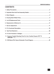
1
USER
K
MANUAL
Easi-feeder 70
Easi-feeder 80
Easi-feeder 90
Easi-feeder 100
Easi-feeder 115
JUNE 1997
Registered Address
6th Street, National Agricultural Centre, Stoneleigh Park,
Kenilworth, Warwickshire CV8 2RL
Tel: 01203 690903 Fax: 01203 690808
Richard Keenan and Company Ltd.,
Borris, Co Carlow, Ireland
Tel: 0503 73214 Fax: 0503 73234
Easi-feeder 140
Easi-feeder 200
The Keenan Easi-feeder is a diet feeder with
a difference.
TO
THE
OWNER
Designed to combine total reliability with
optimum performance, the Easi-feeder is the
heart of a successful complete diet feeding
system.
Not only does it provide fast, efficient mixing
and feed-out, it can also be used for pre-mixing
concentrates and for treating cereals.
High mechanical efficiency means the Easifeeder can be used with relatively low
horsepower tractors and a minimum of moving
parts ensures genuine long life.
At Keenan we realise our customers are our
strength. As a Keenan user not only are you
entitled to our full nutritional management
services whenever you need them, you are also
assured of our prompt and full attention to any
problem at all times.
Simple routine maintenance and correct
operation will ensure you get the very best
from your Easi-feeder.
This manual has been designed to cover all
the information you need to know, but if you
require any further assistance please do not
hesitate to get in touch with us.
1
Page
No.
CONTENTS
2
1. The Easi-feeder principle.
4
2. Safety.
7
3. How to use the weighing system.
9
4. Operating the Easi-feeder.
22
5. Example mixing sequences.
25
6. Maintenance.
26
7. Maintenance checklist .
31
8. Specifications.
33
9. Part numbers.
35
10. Pictorials.
42
11. Warranty.
43
3
The Easi-feeder’s main operating functions
are weighing, mixing and feeding out.
Paddle
WEIGHING
The Easi-feeder’s electronic weighing system
allows exactly the required amounts of
1. THE
EASI-FEEDER
PRINCIPLE
individual materials to be loaded into the
mixing chamber to provide accurate rationing.
The system is based on robust load cells
mounted between chassis and mixing chamber
THE
EASI-FEEDER
PRINCIPLE
Discharge
auger
which send electronic signals to the control box
mounted on the front of the feeder. These
signals are converted into units of weight which
are then displayed on an easily-read digital
The paddle imparts a shearing action on the
display.
Individual loads can be weighed or successive
loads can be accumulated to give total weight
of feed in the feeder.
feed ingredients and produces a consistent and
thorough mix with all types of material
including coarse, wet silage and liquids.
When mixing, a simple guillotine door
separates the mixing chamber from the
unloading auger.
❋J-STAR❋
❋BOX❋
Central paddle
Discharge auger
load cells
Indicator
MIXING
Mixing is carried out by a centrally-mounted
paddle revolving at just 10rpm.
Guillotine door
(closed)
4
MIXING
5
FEEDING OUT
When mixing is complete the PTO is
disengaged and the guillotine door between
the mixing chamber and the discharge auger is
lifted. The auger rotates in the same direction
as the paddles and runs the entire length of the
THE
EASI-FEEDER
PRINCIPLE
mixing chamber.
When the door is lifted, the PTO is engaged
and material is pushed onto the auger and
discharged at the front of the machine. Feedout is even, rapid and in full view of the
operator.
Guillotine door (open)
Central paddle
Discharge
auger
FEEDING OUT
6
2. SAFETY
The Easi-feeder has many safety features
built into its design but its ultimate safe
operation is down to the individual and his
understanding of potential safety problems.
The Easi-feeder is designed to be used as a
mixer wagon for mixing animal feeds. It should
not be used for any other purpose which will
affect its performance or safety.
The following points are guidelines only,
please be vigilant at all times.
1. Use only a PTO shaft with a properly fitted
safety guard and shear bolt.
2. Do not permit any passengers on the
feeder.
3. Always connect the PTO shaft with the
shear bolt end to the tractor.
4. Always make sure that all covers/guards are
fitted and locked closed with the keys
provided.
5. Ensure all trailing leads, hoses etc are well
clear of the PTO.
6. Ensure the feeder and the immediate area
surrounding it are clear of people,
especially children, before commencing
operation.
7. Never remove chain guards or get into the
feeder when it is connected to a tractor.
8. Regularly inspect all chains, sprockets and
moving parts for wear and check all nuts
and bolts for tightness.
9. Load only from the side indicated.
10. Do not exceed 15km/hr (10mph) when
travelling.
11. Exercise extreme caution when turning
right.
12. Always park the feeder on level ground
and apply hand brake when not in use.
13. The ladder on the rear of the feeder is only
to be used as a viewing point for the
mixing chamber. It should not be used as a
means of access to the mixing chamber.
7
SODA GRAIN WARNING!
The weighing system has been designed to
be simple to operate, accurate and robust.
Before treating grain with Caustic Soda, read
The weighing system is made up of four load
carefully the instructions provided by KEENAN
cells and an indicator unit at the front of the
paying particular attention to the Safety
machine. Each of the load cells is connected to
Warnings.
the indicator unit.
When finished treating grain, clean out any
SAFETY
treated grain remaining in the Mixing and/or
Auger chambers. Remember that this grain
should not be fed to animals for at least 4 days
after treating.
Note: The 20 cubic weighing system has
3. HOW
TO USE
THE
WEIGHING
SYSTEM
Weightonix load cells and indicator. Refer to
seperate manual for the EF200. The system
described below refers to the J-star indicator
which is common to all models except the
EF200.
Caution is the key word at all times.
❋J-STAR❋
❋BOX❋
Indicator
BLOW UP
Load cells
Load cell
Load cell
The system uses 12 volt DC power from the
tractor which is connected to the indicator unit.
The indicator unit therefore has two leads
entering it, one from the load cells and one
from the tractor.
The indicator unit is mounted on a swinging
arm to allow it to be placed in the best position
possible for ease of operation and visibility.
Weights of loads are displayed in kilograms
with increments of 5kg being used. The unit is
capable of measuring up to 20 tonnes.
The system is maintenance free being fully
electronic with no moving parts. All
components are sealed against moisture and
dust and are resistant to frost and corrosion.
8
9
SCALE BOTTOM PANEL CABLE
CONNECTIONS:
WEIGHING – INSTALLATION REQUIREMENTS:
Indicator Mounting:
The indicator is easily attached to the
Indicator Mounting Bracket by hooking the top
over the plate and securing the bottom with
two (2) bolts and nuts.
HOW
TO USE
THE
WEIGHING
SYSTEM
Power Connection:
The power cable should be connected directly
to a vehicle battery or regulated power supply.
The scale end of the power cable is attached to
the ”POWER” connector located on the bottom
HOW
TO USE
THE
WEIGHING
SYSTEM
panel of the scale. Connect the RED wire from
the power cable to +12 VDC and the BLACK
wire to GROUND.
The indicator is fused internally at 4 amps.
The FUSE on the bottom panel of the indicator
is for the ALARM ONLY.
Power Cable Connections:
Wire Colour
Wire Function
RED
Battery (+12 VDC)
BLACK
GROUND
ORANGE
Remote Alarm Out +
BLUE
Remote Input
Remote Alarm Connection:
Load Cell Connection:
The indicator is designed to operate with
strain gauge load cells. To connect the load
cells, attach the junction box cable to the
“LOADCELL” connector on the bottom panel of
the scale.
Weighing – System Operation:
Turning ON the Scale:
Step 1) Press [ON].
If a remote 12 VDC alarm is to be used,
connect the +12 VDC side of the alarm to the
power cable orange wire and the GROUND side
of the alarm to the frame. The alarm output is
fused for a maximum drain of 10 amps.
Remote Input Connection:
If the Remote Input Connection is to be used,
connect one side of a ‘Normally Opened’ switch
or relay contact to the BLUE wire of the POWER
cable, and the other side to the frame or other
GROUND connection. Closing the switch or
relay is the equivalent of pressing the (TARE)
key on the indicator i.e. gives a ‘Temporary’
‘Zero’ point.
10
11
A brief message will be displayed (”HELLO“).
The ZERO/BALANCE will ”balance off“ feeder
weight.
The scale then selects the GROSS weighing
mode.
”ZERO“ is displayed to show completion of
the step and the scale is then placed in the
GROSS mode.
GROSS mode displays the weight change since
the unit was last ZERO/BALANCED.
Pressing [ON] a second time during normal
system operation starts the self test.
HOW
TO USE
THE
WEIGHING
SYSTEM
Turning OFF the Scale:
Step 1) Press [OFF].
HOW
TO USE
THE
WEIGHING
SYSTEM
Pressing only the [ZERO] key will cause the
message ”TO ZERO/BALANCE PRESS NET/GROSS
– THEN ZERO“ to be displayed.
If the supply power is below the ”low battery
threshold“ (10.5 Volts), the message
”INDICATOR CANNOT BE ZERO/BALANCED –
LOW BATTERY VOLTAGE“ is displayed. The
message “LO BAT” will be periodically shown
on the display (approx. every five seconds) to
alert the operator of the low battery condition.
Using the Help Key:
The [HELP] key provides additional
information about the weighing modes,
setup/calibration, and keypad entries.
Step 1) Pressing [HELP] while displaying weight
will display information about the last key
Loss of power does not affect the ”set-
pressed.
up/calibration“ values.
To Zero-Balance the Scale:
Step 1) Press the [NET/GROSS] key and within
three seconds,
Step 2) press the [ZERO] key.
12
13
To Select Gross Mode:
or
GROSS mode displays the weight change since
Step 2) If in Gross mode, press [NET/GROSS]. The
the unit was LAST ZERO/BALANCED.
[NET/GROSS] key is an alternating action key. If
Step 1) Press [NET/GROSS]
the scale is in the GROSS mode, pressing the
[NET/GROSS] key will place it in the NET mode.
If the scale is in the NET mode, pressing the
[NET/GROSS] key will place it in the GROSS
HOW
TO USE
THE
WEIGHING
SYSTEM
HOW
TO USE
THE
WEIGHING
SYSTEM
mode. If in LOAD-UNLOAD mode, press
[NET/GROSS] two (2) times.
If the ”TARE“ function has not been
previously performed, the unit will stay in the
Gross mode and the message ”FOR NET MODE
PRESS TARE“ will scroll across the display.
NOTE: The scale is in NET mode if there is a
flashing arrow pointing toward the NET text
just above the [TARE] key.
To Enter a Preset:
Press the [NET /GROSS] key if in the NET or
LOAD/UNLOAD mode.
NOTE: The scale is in GROSS mode if there is a
flashing arrow pointing toward the GROSS text
above the [NET/GROSS] key.
To Select Net Mode:
NET mode displays the weight change after a
Step 1) Use the numeric keypad to enter the
desired preset weight.
Step 2) Press either [NET/GROSS] or
[LOAD/UNLOAD] to enter the preset value and
select the ”display mode“.
The ’PRESET‘ annunciator outer triangle will
turn ON when the preset amount is entered.
TARE has been performed. TARE is temporary
”zero“ point.
Step 1) If the scale ”TARE“ weight has not been
entered, press [TARE] to acquire a ”zero“.
14
15
Once the preset has been entered, the display
To Clear the Preset & Alarm:
can show the weight data in three (3) different
Step 1) Press the [CLEAR] key.
”display modes“.
The three display modes are:
”GROSS MODE“ The gross weight is displayed
by pressing the [NET/GROSS] key. As ingredients
HOW
TO USE
THE
WEIGHING
SYSTEM
are loaded, the weight display will count
upward toward the preset value. As ingredients
are unloaded the weight display will count
down to the preset value.
”LOAD/UNLOAD MODE“ Press the
HOW
TO USE
THE
WEIGHING
SYSTEM
[LOAD/UNLOAD] key to display the amount
remaining to be loaded or unloaded. As
ingredients are loaded OR unloaded, the
display will count down from the entered
preset weight until it reaches zero.
”NET MODE“ The weight added since the preset
has been entered is displayed by pressing the
[NET/GROSS] key two (2) times if in the PRESET
LOAD/UNLOAD MODE, one (1) time if in the
At this time, a new preset can be entered or by
pressing the [CLEAR] key a second time (with a
flashing zero ”0“ shown on the display) the
scale will return to weighing.
PRESET GROSS MODE. As ingredients are
Using the Pre-Alarm:
loaded, the weight display will count upward,
The Pre-Alarm feature is an ”early warning“ for
as they are unloaded the weight display will
the preset. For example, if the Pre-Alarm is set
count down.
to 100 and the preset is 1000, the preset alarms
Switching between these display modes is
will flash during the last 100 kgs of the preset.
possible at any time by simply pushing the
The alarms are continuous once the preset is
appropriate keys.
active. This allows more accuracy in reaching
Before the preset weight is reached, the pre-
the preset.
alarm is activated. This causes the preset display
annunciator, the front panel alarm light, the
output relay, and the alarm horn all to pulse in
sequence with the alarm light.
Set the pre-alarm value to”0“ to prevent the
alarm output from pulsing.
When the preset weight is reached, the front
panel alarm light, the output relay, the
’PRESET‘ annunciator, and the alarm horn will
all be held ON.
16
17
Change the Pre-Alarm Weight:
Step 3) Use the numeric keypad to select a pre-
Step 1) Press and hold the [NET/GROSS] key,
alarm weight.
then press the [ON] key. Continue holding both
keys until the indicator beeps and displays the
message ”P-ALM“. The ’CAL‘ annunciator will
be flashing and the current pre-alarm weight is
displayed.
HOW
TO USE
THE
WEIGHING
SYSTEM
HOW
TO USE
THE
WEIGHING
SYSTEM
Step 4) Press the [ON] key. The display will
advance to the next setup value.
Step 2) Press the [CLEAR] key to erase the
current weight value.
Step 5) To exit setup and return to weighing,
press and hold the [TARE] key, then press the
[ON] key.
18
19
TROUBLESHOOTING
System Weighing Innacurately
If you suspect that the system is weighing
If you experience problems in the operation
inaccurately, check all four weighcells to make
of the Weighing System, read through this
sure that they are mounted correctly. If the bolt
Troubleshooting section first before contacting
through the weighcell has come loose or
KEENAN SERVICE.
broken, the weighcell can turn upside-down
Reading Drifting
HOW
TO USE
THE
WEIGHING
SYSTEM
If the reading on the Indicator is drifting or
does not stay steady, the most likely cause of
the problem is dampness/moisture in or around
the Indicator or cables. Please follow these
steps to locate and correct the problem.
1.
resulting in that weighcell giving an inaccurate
HOW
TO USE
THE
WEIGHING
SYSTEM
reading. (As you face the back of the machine
the cable should be to the Right Hand Side of
each of the rear Weighcells. As you face the
front of the machine the cable should be to the
Right Hand Side of each of the front
Disconnect the Display Cable (Junction Box
Weighcells.) If a Weighcell is turned upside-
to Indicator). Check both the plug on the
down, remove the bolt (3/8" x 31/2") and turn
cable and the connector on the Indicator for
the Weighcell.
dampness and/or corrosion of the terminals.
To check that the system is weighing
If any dampness is found dry it off
correctly, get some known weight (e.g. A bag
thoroughly with a hair drier. If corrosion is
of fertiliser) and place it on each corner of the
found on the terminals then clean
machine in turn. You should get the same
thoroughly. Reconnect cable and test.
reading for each corner. If one corner returns a
2. Remove the cover from the Junction Box
and check for any loose wiring or dampness.
Again dry off any dampness and rectify any
loose or bad wiring.
3. Check Weighcell plugs for dampness and
also check Weighcell cables for any breaks
and/or dampness.
significantly different reading from the other
three then this points to a faulty weighcell on
that corner.
Indicator will not Switch ON
If the Indicator will not switch ON the most
likely cause of the problem is a faulty Power
Cable or bad connection at the Power point on
the tractor. Check the Power cable thoroughly
If the above measures do not rectify the
for breaks and also make 100% sure that you
problem then contact KEENAN SERVICE for
are getting Power from the tractor. Note that
further assistance.
the Indicator is Fused Internally and that the
Fuse located on the bottom panel of the
Indicator is for an External Alarm. If these
checks do not solve the problem, contact
KEENAN SERVICE.
20
21
The Easi-feeder is designed for ease-of-use
3. Loading of the feeder can now start.
and low power requirement. For maximum
Loading should be carried out only from
performance it is recommended that the feeder
the side indicated to avoid the risk of
be used with a tractor in the 75-80hp range.
catching loading shovels/silage grabs in
Until the full capabilties of the Easi-feeder are
the revolving paddles.
understood by new operators, it is recommended
4. Use the weigher system to ensure the right
that smaller quantities are used and that
4. OPERATING
THE
EASI-FEEDER
overloading is avoided.
HITCHING UP
1. After ensuring the Easi-feeder is parked on
OPERATING
THE
EASI-FEEDER
amounts of ingredients are being added in
line with the desired rations (see section 3).
5. Where liquids are being used, these
should be loaded first followed by
level ground hitch-up the feeder to the
other concentrates and then other
tractor towbar.
ingredients which form smaller
2. The PTO shaft should be attached with its
shear bolt end coupled to the tractor’s
fractions of the total mix.
6. Last of all add the feed ingredient which
output not to the feeder’s drive box. Make
forms the largest part of the ration. This
sure that the PTO guard is in good
allows lesser constituents to be thoroughly
condition and well secured.
mixed together before the addition of the
3. Connect the hydraulic line from the
guillotine door mechanism to a doubleacting spool valve and the line from the
brakes to a single acting valve.
4. Ensure the power lead from the weighing
system is connected to the tractor battery
via a direct fused line (see section 3).
LOADING/MIXING
1. If the feeder has been transported to a new
area, again check it is on level ground. This
will ensure all feedstuffs are distributed
evenly for accurate weighing and thorough
mixing.
2. Make sure the guillotine door is closed and
main bulk of the ration and ensures they
are evenly spread throughout the mix.
7. Allow the mixture to circulate in the
feeder until all loading is complete.
Disengage the PTO and transport the
feeder to unloading point.
Note: As a rule mixing is complete as soon as
the last ingredient is loaded.
When mixing cereal pre-mixes and meal-only
diets, set the engine speed to about 18002000rpm and do not mix more than 2.5 tonnes
at any one time. For best results, leave the
feeder running for three to four minutes after
the last ingredient has been added to ensure
a thorough mix.
that hydraulic pressure is applied. With
When using straw in the ration, it is advisable
tractor engine speed at approx 1500rpm,
to leave the feeder mixing for a further 2-3
engage the PTO. As a general rule engine
minutes after loading is complete.
speed during loading should be as low as
possible without the risk of stalling.
22
23
UNLOADING
INGREDIENTS
1. Position the feeder discharge chute over the
start of the feeding trough and open the
guillotine door to its full height.
2. Engage the PTO and set the engine speed
to 1800-2000rpm. Select and engage a low
OPERATING
THE
EASI-FEEDER
ratio forward gear and the feed-mixture
will be discharged.
3. Discharge time depends on materials used
and the total load, but moderate loads of
silage-based rations will take in the region
of two minutes to fully unload.
4. If a run of trough space is finished before
the feeder is fully unloaded, disengage the
PTO and turn around before going back
down the passage or moving to a new
trough. Engaging the PTO will commence
the feed-out procedure once more.
Warning - If you need to lower the guillotine
door because of height restrictions when
manoeuvering, allow the door to descend
slowly under its own weight rather than
forcing it down with hydraulics. Disengage the
tractor hydraulics and operate the lever. Before
engaging the PTO again ensure hydraulics are
reconnected and guillotine door is fully open.
Remember . . .
Always use the lowest gear possible as this
will ensure maximum power is delivered to the
unloading mechanism.
The guillotine door should never be used as a
metering device. In operation it should be used
only in one of two positions - fully opened
(unloading) or fully closed (mixing).
Warning - Always disengage the PTO before
attempting to turn any corner once the Easifeeder is hitched up.
24
5. EXAMPLE
MIXING
SEQUENCES
SEQUENCE
Dairy Ration (1)
Molasses
Ruminant Fishmeal
Brazilian Soya
Caustic Treated Wheat
Distillers Grains
Barley Straw
Silage
1
2
3
4
5
6
7
Dairy Ration (2)
Brewers Grains
Sugar Beet Pulp
Ruminant Fishmeal
Brazilian Soya
Caustic Treated Wheat
Barley Straw
Silage
1
2
3
4
5
6
7
Beef Ration (1)
Molasses
Minerals
Maize Gluten
Barley Straw
Silage
1
2
3
4
5
Beef Ration (2)
Minerals
Distillers Grains
Fodder Beet
Brazilian Soya
Caustic Treated Barley
Barley Straw
Silage
1
2
3
4
5
6
7
Remember, as a general rule the sequence is
as follows :
1) Liquids. 2) Smallest Quantities.
3) Grain and Nut Textures. 4) Fibre. 5) Silage
In the case of chopping machines, load as
follows: Liquids, then material to be chopped.
Allow time for chopping to take place. Add
remainder of materials as in sequence above.
Where liquids are not used the material
needing chopping should go in first with a
small quantity of wet forage added.
25
The Easi-feeder has been designed for
3.
After each season remove both chains by
optimum performance with a minimum of
removing the joiner links - see diagram -
maintenance.
and wash off all dirt and oil using paraffin.
Chains and bearings have been kept to a
Dry the chains before soaking overnight in
minimum without compromising function and
oil. Refit.
there are only eleven grease points on the
entire machine. All components are of high
6. MAINTENANCE
quality and provide excellent durability.
MAINTENANCE
Regular routine maintenance will ensure your
Easi-feeder gives you the best results with a
minimum of problems.
Prior to carrying out any maintenance on the
machine, always disconnect the P.T.O. and
hydraulic hoses from the tractor.
CHAINS
1.
Chain joiner links
Each week check the chains and adjust
tension accordingly.
Primary drive chain is adjusted by turning
the drive gearbox adjuster nut (A) to
remove excess slackness and tension by
turning chain tensioning jockey arm (B).
Secondary drive chain is adjusted by
turning the jockey arm (C).
GREASE POINTS
1.
Bearings - Each week apply grease to the
five bearings with nipples. The five
bearings are as follows;
Two main bearings at the rear of the Easi-
Both chains should be adjusted to prevent
feeder (A + B)
sagging or whipping when under load. Do
not overtighten or damage to the bearings
will result.
2.
Each week apply universal oil liberally to
both drive chains.
Grease point B
Grease point A
Secondary drive chain
C
B
26
A
Primary drive chain
27
Two main bearings on the front and rear of
3.
the gearbox drive shaft (C + D)
Slides - Each week apply grease to the two
slide plates on the guillotine door ( I + J)
One bearing on the front of the main rotor
Grease Point I
shaft (E)
Grease Point J
Grease Point F
Grease Point E
MAINTENANCE
MAINTENANCE
Grease Point G
Grease Point C
Grease Point D
Note: Check the guillotine door is able to move
freely each day and grease as appropriate.
NUTS AND BOLTS
2.
Bushes - Each week apply grease to the
1.
After the first day, and every day
thereafter, inspect wheel nuts.
2.
After the first week, and each week
thereafter, check all nuts and bolts,
including bearing nuts, for tightness.
four bushes with grease nipples. The four
bushes are as follows;
Two bushes on the jockey sprockets (F + G)
Two bushes on the guillotine door lift arms
TYRES
(G + H)
Grease Point G
Grease Point H
1.
Each week check the tyres for wear and
damage.
2.
Each week check tyre pressures. Optimum
tyre pressures are as follows;
PLEASE CHECK WHEEL NUTS AT REGULAR INTERVALS
Torque
28
Stud Type
LB/FT
N.M.
M18
250
337
M20
300
405
M22
400
540
29
Maximum inflation pressures:
Pressure
WHEELS
1.
MAINTENANCE
Tyre
Bar
PSI
30 – 11.5 – 14.5
7
101
12.5/80 – 15.3
5.3
76
12.0 – 18
5
72
40 – 14
7
101
15/70 – 18
5
72
16/70 – 20
5.45
79
15 x 22.5 (385/65R – 22.5)
5
72
18 x 22.5 (445/65R – 22.5)
6
87
(285/70R – 19.5)
8
116
(275/70R – 22.5)
8
116
(400/60 – 15.5)
5
72
Each season, lever off hub cap, remove split
pin and castle nut and remove hub.
2.
Check seals, bearings, brake shoes, springs,
studs and all other internal parts.
3.
MAINTENANCE
Replace worn parts, re-grease and refit.
Note:
When re-fitting wheels, screw crown nut until
resistance is felt (do not overtighten). Turn hub
for several revolutions to ensure it is completely
bedded. Release crown nut 1/6 of a revolution,
check for movement in hub, and if none, re-fit
split pin.
WHEN REFITTING AND RE-INFLATING
TYRE/WHEEL ASSEMBLIES, A SAFETY CAGE
For non standard wheels or any not specified
on this list please contact Keenan for details of
pressures.
Note: At the end of the season wash the
machine down thoroughly preferably using a
power washer. Grease or oil all lubrication
points and open the draincock.
SHOULD BE USED TO PREVENT POSSIBLE
INJURY.
INCORRECTLY FITTED TYRES ARE DANGEROUS.
PLEASE MAKE SURE TYRE REPAIRS ARE
CARRIED OUT BY EXPERIENCED TYRE FITTERS.
THIS INFORMATION IS GIVEN AS GUIDANCE. IF
IN DOUBT PLEASE CONTACT KEENAN SERVICE.
30
31
DAILY
Electronic indicator: If the machine is to be
Guillotine door: Before using the machine,
stored, remove the indicator unit from the
check that the door opens and shuts fully and
machine and keep in a dry place. Lightly grease
operates smoothly.
the load cell cable connector end, then protect
it with a plastic bag or tape.
WEEKLY (40 HRS)
Wheels: Remove and inspect hub units. Replace
PTO input shaft: Grease the universal joints (2
7. MAINTENANCE
CHECKLIST
nipples) and the sliding half shafts (smear
grease on surfaces).
MAINTENANCE
CHECKLIST
worn parts, regrease and re-fit.
Drive (gear) box: Grease the drive input-shaft
bearings (2 nipples).
Mixing paddle door: Grease the front and rear
mixer-paddle shaft end-bearings (2 nipples).
Feed discharge auger: Grease the auger’s rear
shaft end-bearing (1 nipple). (NB the auger
shaft’s front end-bearing is sealed and does not
need routine lubrication but should be checked
annually for wear).
Guillotine door: Grease the door lift-arm pivot
bushes (2 nipples) and the slide plates (smear
grease on surfaces).
Drive chains: Apply universal-type oil liberally.
Check both chain tensioners are adjusted
correctly (see text).
Tyres: Check that tyres are inflated at the
recommended pressures.
YEARLY (END OF SEASON)
Drive chains: Remove both chains; wash off all
dirt and old oil, using paraffin, then dry. Soak
both chains in oil overnight; or longer, if
possible.
Machine: Before storage, wash the complete
machine, then grease or oil all weekly
lubrication points as above. Open the draincock
in the mixing hopper. Check tyre pressures.
Store the machine under cover or under a
tarpaulin, if possible.
32
33
A
Model
B
8. SPECIFICATIONS
SPECIFICATIONS
C
D
100
115
140
200
A
4.99m
5.85m
5.90m
6.90m
B
3.00m
4.00m
4.00m
5.00m
C
2.95m
2.70m
3.00m
3.25m
D
2.54m
2.30m
2.54m
2.83m
E
2.59m
2.48m
2.73m
2.90m
F
2.76m
2.65m
2.90m
––
G
1.13m
1.10m
1.24m
1.27m
Capacity
10m3
11.5m3
14m3
20m3
Wheels
(12 x 18)
(12 x 18)
(15R 22.5)
(12 x 18)
14Ply 6 Stud 14Ply 6 Stud 8 Stud
Weigher resolution 5Kg
Discharge
F
5Kg
5Kg
14 Ply 6 Stud
5Kg
Side Auger
E
G
Model
70
80
90
A
4.89
4.85m
5.89m
B
3.00m
3.00m
4.00m
C
2.33m
2.70m
2.33m
D
2.12m
2.30m
2.10m
E
2.30m
2.43m
2.30m
F
2.47m
2.60m
2.47m
G
0.96m
1.10m
0.96m
Capacity
7m3
8m3
9m3
Wheels
(12 x 18)
(12 x 18)
(12 x 18)
14 Ply 6 Stud 14 Ply 6 Stud 14 Ply 6 Stud
Weigher resolution 5Kg
Discharge
34
5Kg
5Kg
Side Auger
35
14
Item & Description
9. PART NUMBERS
70
80
90
11 Gearbox Adjuster (Unit)
EF1018/15 EF1018/15 EF1018/15
12 Read Out Arm (unit)
EF102/60
EF102/60
EF102/60
13 Chain
P703
P703
P703
14 Chain
P701
P701
P701
PART NUMBERS
13
Item & Description
100
115
140
200
1
Main Sprocket
EF107/34
EF807/34
EF107/34
P561
2
Bearing (rotor front)
P501
P501
P501
P517
3
Bearing (auger front)
P503
P503
P503
P516
4
Sprocket & Spline Shaft
–
–
–
EF2018/16
5
Sprocket (auger feed)
P555
P559/1
P555
EF209/32
6
Sprocket (auger supply)
EF109/29
EF109/29
EF109/29
EF209/29
7
Front Cross Member
EF1017
EF8017
EF1017
EF2017
8
Gearbox (Unit)
EF1018
EF1018
EF1018
EF2018
9
Bottom Jockey (complete unit) EF1015
EF1015
EF1015
EF1015
EF1014
EF1014
EF1014
12
1
4
11
10
8
5
9
6
3
2
10 Top Jockey (complete unit)
EF1014
11 Gearbox Adjuster (Unit)
EF1018/15 EF1018/15 EF1018/15 EF2018/15
12 Read Out Arm (unit)
EF102/60
EF102/60
EF102/60
EF102/60
13 Chain
P703
P703
P703
P702
14 Chain
P701
P701
P701
P708
7
Item & Description
80
90
1
Main Sprocket
EF707/34
EF807/34
EF707/34
2
Bearing (rotor front)
P501
P501
P501
3
Bearing (auger front)
P503
P503
P503
4
Sprocket & Shaft gear/box
EF1018/11 EF1018/11 EF1018/11
5
Sprocket (auger feed)
P556
P559/1
P556
6
Sprocket (auger supply)
EF109/29
EF109/29
EF709/29
7
Front Cross Member
EF7017
EF8017
EF7017
8
Gearbox (Unit)
EF1018
EF1018
EF1018
9
Bottom Jockey (complete unit) EF1015
EF1015
EF1015
EF1014
EF7014
10 Top Jockey (complete unit)
36
70
EF7014
37
5
Models EF 200
16
3
8
4
2
13
1
17
18
Item & Description
70
80
90
5
Paddles (rear)
EF708/31
EF808/31
EF908/31
6
Paddle Rubber
EF108/28
EF108/28
EF908/29
7
Paddle Front
EF708/34
EF808/34
EF908/34
8
Paddle Rear
EF708/32
EF808/32
EF908/32
9
Paddle Rubber Retainer
7
PART NUMBERS
All Models except EF 200
3
EF708/22
EF808/22
EF118/22
10 Rotor Unit
EF707
EF807
EF907
11 Rotor Seal Rubber
EF107/26
EF107/26
EF107/26
12 Rotor Seal Retainer
EF107/27
EF107/27
EF107/27
13 Paddle Block
EF107/16
EF107/16
EF107/16
14
PART NUMBERS
5
14 Paddle Block
EF107/15
EF107/15
EF107/15
15 Auger Stub Shaft
EF109/10
EF109/10
EF109/10
Item & Description
100
115
7
2
13
8
10
1
140
200
1 Front Rotor Stub Shaft
EF107/7
EF107/7
EF147/7
EF207/7
2 Paddle Flange (outer)
EF107/3
EF107/3
EF147/3
EF147/3
3 Paddle Flange (inner)
EF107/2
EF107/2
EF147/2
EF147/2
4 Paddles (front) C/W Rub
EF108/33
EF118/33
EF148/33
EF208/33
5 Paddles (rear) C/W Rub
EF108/31
EF118/31
EF148/31
EF208/31
6 Paddle Rubber
EF108/28
EF118/28
EF148/30
EF208/28
7 Paddle Front straight
EF108/34
EF118/34
EF148/34
EF208/34
8 Paddle Rear straight
EF108/32
EF118/32
EF148/32
EF208/32
9 Paddle Rubber Retainer
EF108/22
EF118/22
EF148/22
EF208/22
10 Rotor Unit
EF107
EF117
EF147
EF207
11 Rotor Seal Rubber
EF107/26
EF107/26
EF147/26
EF147/26
4
All Models
6
9
17
12 Rotor Seal Retainer
EF107/27
EF107/27
EF107/27
EF107/27
13 Paddle Block
EF107/16
EF107/16
EF147/16
EF147/30
14 Paddle Block
EF107/15
EF107/15
EF147/15
EF147/40
15 Auger Stub Shaft
EF109/10
EF109/10
EF109/10
EF209/10
16 Middle Paddle c/w Rubber –
–
–
EF208/35
17 Middle Paddle straight
–
–
–
EF208/36
18 Paddle Block
–
–
–
EF147/31
16
12
11
15
Item & Description
70
80
90
1
EF107/7
EF107/3
EF107/7
2
38
Rotor Stub Shaft
Paddle Flange (outer)
EF107/3
EF107/3
EF107/3
3
Paddle Flange (inner)
EF107/2
EF107/2
EF107/2
4
Paddles (front)
EF708/33
EF808/33
EF908/33
39
1
PART NUMBERS
40
PART NUMBERS
Item & Description 70
80
90
1
Guillotine Door
EF7010/1
EF8010/1
EF9010/1
2
Rubber Strip
P655
P655
P656
3
Retainer
EF1010/2
EF1010/2
EF1410/2
4
Door Lift Arm
EF8010/5
EF8010/5
EF8010/5
5
Link Arm
EF8010/13
EF8010/13
EF8010/13
Item & Description 70
80
90
6
Ram Bracket
EF1010/10
EF1010/10
EF1010/10
1
P506
P506
7
Hydraulic Ram
P800
P800
P800
8
Retainer Plate
EF8010/7
EF8010/7
EF8010/7
9
Lift Arm Link Bar
EF1010/29
EF1010/29
EF1010/29
Item & Description 100
115
140
200
1
Guillotine Door
EF1010
EF1110
EF1410
EF2010
2
Rubber Strip
P655
P656
P656
P656
3
Retainer
EF1010/2
EF1410/2
EF1410/2
EF2010/2
4
Door Lift Arm
EF1010/5
EF8010/5
EF1410/5
EF2010/5
5
Link Arm
EF1010/13
EF8010/13
EF1410/13
EF1410/13
6
Ram Bracket
EF1010/10
EF1010/10
EF1410/10
EF2010/10
7
Hydraulic Ram
P800
P800
P801
P812
8
Retainer Plate
EF1010/7
EF8010/7
EF1010/7
EF2010/7
9
Lift Arm Link Bar
EF1010/29
EF1010/29
EF1010/29
EF2010/29
Bearing
P506
Item & Description 100
115
140
200
1
P506
P501
P517
Bearing
P506
41
Richard Keenan & Co. undertake to correct by
repair or replacement, at the Company’s
option, any defect of material or workmanship,
which occurs in any of its products within 12
months of delivery to the customer i.e. the first
user (with the exception of commercial users
when the warranty period is six months.)
10. PICTORIALS
11. WARRANTY
Do not open or remove safety guards while
the feeder is connected to the tractor
Keep a safe distance
from this machine
The warranty shall not apply to:
a)
Any machine which has been damaged by
general wear & tear, neglect or improper
use.
b)
Any machine on which the identification
mark has been altered or removed.
c)
Any machine which has not received
normal maintenance such as tightening of
nuts, bolts and chains, normal lubrication
Stay clear of sharp blade
and maintaining correct tyre pressures.
Read the operators manual
d)
Any machine which is not used in
accordance with the Company’s
recommendations.
e)
Any machine that has been repaired or
modified by person(s) not authorised by
Richard Keenan & Co., which in the
Company’s judgement has affected the
performance or reliability.
Do not stand on the ladder
while the machine is working
Lift to open
f)
Any second hand machine which has not
been factory refurbished.
The sole and exclusive claim against Richard
Keenan & Co., made by the first or subsequent
user, shall be for the repair or replacement of
Chain adjuster
defective parts, and no other claim (including
but not limited to incidental, indirect or
consequential damages for lost profits, lost
sales, injury or property, or any other loss) shall
be available.
Air brake positions
42
43
Oral statements made by any person(s)
Manufacturer
(including Dealers and representatives of Richard
Richard Keenan & Co. Ltd.,
Keenan & Co.) which are inconsistent or
Borris,
conflicting with these conditions, shall not
Co. Carlow,
constitute warranties unless given in writing and
Ireland.
signed by a Director of Richard Keenan & Co.
Certifies that the Keenan Easi-feeder to which
WARRANTY
PRODUCT CHANGES AND IMPROVEMENTS
Due to our policy of continuous improvement,
Richard Keenan & Co. reserves the right to
make changes in design, to add improvements
or to otherwise modify any of its products
without incurring any obligation on products
previously supplied.
EC DECLARATION
OF CONFORMITY
according to
Directive
89/392/EEC as
amended
this declaration relates, corresponds to the
essential safety requirements of the Directive
89/392/EEC as amended.
To conform to these essential health and
safety requirements, the provisions of the
following harmonized standards were
particularly considered.
EN 292 - 1, 2, EN294, EN-16-T, EN 1152
BS 6792, ISO 11684.
Date: 22nd December 1994
Signed: ........................................................
Gerard Keenan,
Managing Director.
44