1
PART NO. Z1-002-642, IB00325A
Jun. 2013
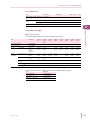
INDEX
4
Hardware Configuration Concept 8
Software installation and
Hardware configuration
12
Test Condition Editor
USER’S MANUAL
PFX2000 Series
Application Software
SD002
BPChecker2000
Ver.3.1
Before entering the data of the
test conditions
23
Setting the Module
24
Enter the battery information
26
Setting the Protections
27
Settinn the Impedance
Measurement
30
Setting the Sequence
34
About Sequence Sheet
37
CC-CV Charge mode
38
CC Charge mode
39
Pulse Charge mode
40
The Setting Description for
the Charge Conditions
43
Predischarge
46
CC Discharge mode
47
CP Discharge mode
48
CC-Pulse Discharge mode
49
CP-Pulse Discharge mode
51
The Setting Descriptions for
the Discharge Conditions
53
Saving the test conditions file
55
Common Sequence Templete
56
Range of Test Condition Settings 58
Test Executive
Before executing test
65
Binding Channels to Groups
66
Assigning Test Conditions
67
Executing Tests
69
Resetting Alarms
78
Synchronized Testing with a
Temperature Chamber
80
Impedance Measurement
82
Alarms
90
Folders and Files
104
Graph Viewer
Before analyzing test results
109
Displaying Graphs
110
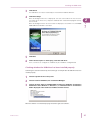
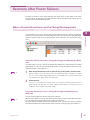
BPChecker2000 is a dedicated application software for the
PFX2000 Series Charge/Discharge Battery Test System and
the PFX2500 Series Charge/Discharge System Controller.
BPChecker2000 enables you to set the conditions of the
battery charge/discharge characteristics tests, execute the
tests, and analyze the test results on a PC.
Other company, brand, and product names provided in this
manual are trademarks or registered trademarks of their
respective holders.
Copyrights
The contents of this manual may not be reproduced, in whole
or in part, without the prior consent of the copyright holder.
The specifications of this product and the contents of this
manual are subject to change without prior notice.
Package Contents
© 2009-2013 Kikusui Electronics Corporation
• CD-ROM containing the program
• User’s Manual (Z1-002-642)
Safety Precautions
How to Read This Manual
This manual is intended for first-time users of the
BPChecker2000. It describes required environment settings,
installation procedure for the application software, and gives
an overview of various programs.
If you find any incorrectly arranged or missing pages in this
manual, they will be replaced. If the manual gets lost or soiled,
a new copy can be provided for a fee. In either case, please
contact Kikusui distributor/agent, and provide the “Kikusui Part
No.” given on the cover.
This manual has been prepared with the utmost care;
however, if you have any questions, or note any errors or
omissions, please contact Kikusui distributor/agent.
Before starting battery tests using this application software,
please thoroughly read the PFX2000 Series or PFX2500
Series Operation Manual that describes the system hardware.
Use extreme caution to make correct connections and handle
the components of the system properly. Improper connections
or handling can lead to serious accidents such as damage to
or explosion of the DUT (battery).
The system is equipped with many functions for protecting the
DUT (battery) both by hardware and software. Some of the
protection functions enable you to set appropriate values
according to the test conditions. Unless there is a special
reason not to do so, use these protection functions when
performing tests.
Notations used in this manual
Product Version Covered
This user’s manual covers BPChecker2000 version 3.1x.
The version of the BPChecker2000 can be referred to the
"Information of the BPChecker2000" in the HELP menu.
Related manuals
The detailed information for the PFX2000 series and PFX2500
series, please refer to the operation manual respectively.
Help File
You can open the help file from the Help menu of
BPChecker2000. The help file includes all the information in
this manual except the installation procedure. It also
includes some contents that are not covered in this manual.
The Group Administrator can be referred to only the HELP
file (it can be viewed by the F1 key).
• In the interest of brevity, the PFX2000 Series Charge/Discharge Battery System shall be hereafter reffered to as the
“PFX2000 Series”.
• In the interest of brevity, the PFX2500 Series Charge/Discharge System Controller shall be hereafter reffered to as
the “PFX2500 Series”.
• In the interest of brevity, the BPChecker2000 Application
Software (SD002) shall be hereafter reffered to as the
“BPChecker2000”.
• In the interest of brevity, the Voltage of DUT (battery) shall
be hereafter reffered to as the “Battery voltage”.
CAUTION
Indicates a potentially hazardous situation which, if
ignored, may result in damage to the product and other
property.
Start Guide
PDF documents (PFX2011 tutorial.pdf for the PFX2011,
PFX2021 tutorial.pdf for the PFX2021) in the “tutor” folder
on the CD-ROM. The guides are structured so that even
first-time users can easily run the tests by using the sample
test conditions file in the same folder.
Indicates information that you should know.
See
Indicates reference to detailed information.
Graph Viewer Operating Procedure
A PDF document named Graph Viewer.pdf in the “tutor”
folder on the CD-ROM. This document explains the operating procedures of the Graph Viewer, a test result analysis
program. This PDF document uses manu screen images of
the Graph Viewer so that even first-time users can easily
understand the procedure.
>
Indicates menu settings and setting of Test Condition
Editor that you select. The menu item to the left of the >
symbol is a higher level menu.
Trademark acknowledgements
Microsoft, Windows, and Visual Basic
trademarks of Microsoft Corporation, USA.
are
registered
Pentium is a trademark of Intel Corporation, USA.
National Instruments, NI-488, and NI-488.2 are the registered
trademark of National Instruments Corporation, USA.
2
BPChecker2000
Edition of BPChecker
Maximum Connections
There are two editions of BPChecker2000: Full Edition and
Basic Edition.
By using one control unit, you can connect 120 channels to the
PFX2000 Series.
Full Edition
The number of devices that you can connect to a PFX2500
Series differs depending on the option boards that are
installed and the controller unit's firmware version. You cannot
use the control unit's TP-BUS2.
This edition provides you with all the functions of the
BPChecker2000.
The Full Edition of the BPCheker2000 can control up to 2 units
of the control unit PFX2121 by the USB port.
The number of PFX2500 Series devices that you can connect
differs depending on the option boards that are installed and
the controller unit's firmware version. See “Maximum
Connections.”
By using one control unit, you can connect 120 channels to the
PFX2000 Series. When the impedance measurement unit
PFX2211 is added, the PFX2000 series can perform the
impedance measurement applied for all channels connected
with one control unit.
If the PC is capable of USB communications, temperature
chambers (by Espec Corp.) can be controlled externally for
synchronized testing.
Basic Edition
PFX2500
Series
Firmware
Option Board
Control Unit
PFX2121
Firmware
Version
Maximum
Connectio
ns
Cannot be
installed
1.00 or later
15
Not installed
1.00 or later
15
1.xx
Cannot be
connected
2.00 or later
7*2
Version*1
1.xx
2.00 or later
Installed
*1. PFX2500s whose versions are 1.xx and 2.xx cannot be
connected together.
*2. If you want to record data at the highest speed (1-second
interval), connect three devices or less.
This edition provides you with limited functions of the
BPChecker2000.
Basic Edition enables you to control one of PFX2121 via the
USB port. The maximum number of charge/discharge power
supply channels that can be controlled is limited to 2. You
cannot add the impedance measurement unit, but
synchronized temperature chamber control is equivalent to
that of the Full Edition.
Full Edition
Basic
PFX2000 PFX2500 Edition
series
series
channels*1
BPChecker2000 consists of the five programs.
Hardware Config Wizard
Comparison of Edition
Number of controllable
Program Construction
Up to 240 Up to 30 Up to 2
channels channels channels
Ability to use the
Possible
Impedance Measuring Unit
Not
possible
Not
possible
Synchronized operation
Possible
with temperature chambers
Possible
Possible
*1. When using a PFX2021 Charge/Discharge Power Supply
unit, the number of controllable channels is reduced to onehalf.
This program is used to detect the charge/discharge power
supply units that are connected to the control unit and
configure the connection environment with other hardware
devices (impedance measurement unit, temperature chamber,
etc.).
Group Administrator
This program is used to create or delete groups for performing
tests. The HELP can be viewed by the F1 key.
Test Condition Editor
This program is used to create and edit all test conditions
related to charge/discharge tests.
Test Executive
This program is used to execute charge/discharge tests
according to the test conditions file that you created using the
Test Condition Editor.
Graph Viewer
This program is used to display graphs of the test data created
by the Test Executive on the screen and print the graphs.
BPChecker2000
3
System Requirements
• The PC equipped with the Pentium IV or the higher specification.
• Windows2000 Professional (SP4+Update Rollup1), Windows
XP (SP2 or later, x86, Windows Vista (x86, x64), Windows 7
(x86, x64), Windows 8 (x86, x64)
• Memory (RAM) : 512 MB or greater
• Hard disk : 50 MB or greater of disk space
• Display monitor : must be capable of a minimum resolution
of 1024 X 768 or better (DPI setting : 96 DPI)
• CD-ROM Drive
• Mouse
• Free USB ports to connect at least the number of control
units to be used
• Printer
Communications with the temperature
chamber
• Temperature chambers by Espec Corp. that can be controlled using the RS485.
• RS485-to-USB converter of the Espec Corp. recommended.
The VISA library must be installed in the PC.
RS485 Protocol
4
Adress
1 to 6
Data bits
8 bit
Transmission
mode
NOMAL
Parity bit
NONE
Bit rate
4800 bps
Delimiter
CR + LF
Stop bits
2 bit
BPChecker2000
Contents
4 Test Execution
Starting the Test Executive 64
1
Before executing test 65
Preface
Binding Channels to Groups 66
Hardware Configuration Concept 8
Assigning Test Conditions 67
Executable Charge/Discharge Tests 9
Executing Tests 69
Flow of Test Procedure 10
Stopping Tests 70
Resuming Tests 72
2
Set Up
Terminating Tests 75
Software installation and Hardware
configuration 12
Installing the VISA Library 12
Installing the BPChecker2000 13
Resetting Alarms 78
Recycle the Channel 76
Changing the Test Conditions during the Test
79
Synchronized Testing with a Temperature
Chamber 80
Installing the USB driver 14
3
Configuring the Hardware 16
Impedance Measurement (when PFX2211 is
used) 82
Creating Test
Conditions
Properties Display 83
Recovery after Power Failures 87
Starting the Test Condition Editor 22
Alarms 90
Operation Examples When Connections Are
Improper (PFX2000 series only) 96
Creating Test Conditions Files 22
Troubleshooting 100
Before entering the data of the test conditions
23
Folders and Files 104
Setting the Module 24
Enter the comment 26
Enter the battery information 26
5
Analyzing Test Results
Starting the Graph Viewer 108
Setting the Protections 27
Before analyzing test results 109
Setting the Recording Method 29
Displaying Graphs 110
Setting the Impedance Measurement (when
PFX2211 is used) 30
Changing the type of C/D graph display 115
Setting the Cell Voltage/Temp (Only on the
PFX2500 Series) 31
Printing Graphs 117
Setting the Life Judgement 33
Changing the type of Life graph display 116
Saving Graphs 118
Setting the Sequence 34
About Sequence Sheet 37
Seq Sheet - CC-CV Charge mode 38
Seq Sheet - CC Charge mode 39
Seq Sheet - Pulse Charge mode (PFX2000
series only) 40
The Setting Description for the Charge
Conditions 43
Seq Sheet - Predischarge 46
Seq Sheet - CC Discharge mode 47
Seq Sheet - CP Discharge mode 48
Seq Sheet - CC-Pulse Discharge mode 49
Seq Sheet - CP-Pulse Discharge mode (except
the PFX2011) 51
The Setting Descriptions for the Discharge
Conditions 53
Saving the test conditions file 55
Common Sequence Templete 56
Range of Test Condition Settings 58
BPChecker2000
5
6
BPChecker2000
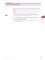
Preface
This chapter describes information you should
know before using BPChecker2000.
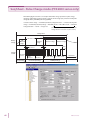
Hardware Configuration Concept
Controllers
The concept of controllers as viewed from BPChecker2000 is the same as the actual hardware
configuration. Instrument ID (1 or 2) refers to the number that is set using the ID switch on the front
panel of the PFX2121 Control Unit.
Channels
The concept of channels of BPChecker2000 is simplified greatly as compared with the actual
hardware configuration. From BPChecker2000, all the channels that are connected to a single
control unit appear as they are connected directly.
Channels contain position information called node numbers.
PFX2000 series
Node numbers are automatically determined from the combination of the frame address,
which is assigned to each frame, and the node address, which is automatically determined by
the position in which the corresponding unit is installed in the frame. The frame number is set
using the FRAME switch on the rear panel of the frame. However, the user cannot arbitrary set
the node address.
PFX2500 series
The node number is set using the S1 switch on the rear panel of the system controller.
The BPChecker2000 determines the channel by combining "Instrument ID" and "Node number".
Group
Group is a concept that does not exist at the hardware level, but exists in BPChecker2000. Group is a
collection of channels that share a set of test conditions. Grouping multiple channels with the same
test conditions offer many benefits such as the simplification of operations and hierarchical
classification of test results on graphs.
See
p. 9
The assignment of temperature chamber is also done at the group level when performing tests in
synchronization with the temperature chamber.
You can create up to 64 groups. There is no limit on the number of channels that are bound to a
single group. Channels present in another controller can also be mixed freely. Groups are identified
by their names. Unlike controllers and channels, there are no numbers for identifying groups.
If a new group is created, the group does not contain any channels. Therefore, you must bind at
least one channel to a group. You can also unbind channels that are already bound or delete groups
that are no longer needed.
Impedance measurement unit
When using the impedance measurement unit PFX2211, the internal impedance measurement of
the battery becomes possible (applied only for the PFX2000 series).
The PFX2211 is not specified explicitly on the BPChecker2000 (The impedance measurement unit
can be used by the configuration setting). At the hardware level, one impedance measurement unit
corresponds to one controller. All the channels within the same controller system share a single
impedance measurement unit. Consequently, the impedance measurement of each channel is
performed in order according to a waiting list principle. BPChecker2000 automatically handles the
waiting list process.
8
BPChecker2000
Executable Charge/Discharge Tests
The synchronization of temperature chambers is assigned at the group level. Since BPChecker2000
can create multiple groups, temperature chambers can be controlled independently per group.
Note that the maximum number of temperature chambers that can be controlled is six. This means
that temperature chambers cannot be assigned to all groups (the maximum number of groups is
64).
1
Preface
Temperature chambers
PC
Controller 1
*1
*1
Impedance measurement unit 1 (PFX2211 used only*2)
Channel 001
Channel 120 (PFX2000 Series)/ 015 (PFX2500 Series)
Controller 2
*1
*1
Impedance measurement unit 2 (PFX2211used only*2)
Channel 001
Channel 120 (PFX2000 Series)/ 015 (PFX2500 Series)
Group 1
Temperature chamber
Reference to each channel (binding)
Group 2
Temperature chamber
Reference to each channel (binding)
*1 When the PFX2021 Charge/Discharge Power Supply unit is used, only
odd-numbered channels are valid.
*2 PFX2000 Series only
Executable Charge/Discharge Tests
The following seven types of charge/discharge tests can be executed using BPChecker2000.
The type of test is varied by the charge and discharge unit. Please refer to the operation manual of
the PFX2000 series or the PFX2500 series used for details.
Charge
• Constant current/constant voltage charge (CC-CV)
• Constant current charge (CC)
• Pulse charge
Discharge
• Constant current discharge (CC)
• Constant power discharge (CP)
• Constant current/pulse discharge (CC-Pulse)
• Constant power/pulse discharge (CP-Pulse) (when using the PFX2021)
These tests can be arbitrary combined to create test conditions using the Test Condition Editor and
executed using the Test Executive.
BPChecker2000
9
Flow of Test Procedure
If you are using BPChecker2000 for the first time, carry out the following procedure.
1
Configure the hardware.
Start the Hardware Config Wizard.
Set the number of control units and the use of impedance measurement units
(PFX2000 series only) and temperature chambers.
Organize the channels separately for each control unit system.
For the system with the PFX2500 series, it is required to set the model information of
the connected DC power supply and the electronic load.
2
Create test conditions.
Start the Test Condition Editor.
Create a test conditions file.
Create a special folder (group) that is recognized by the BPChecker2000 system, and
specify the group folder name and path.
Specify the group folder in which to save the test conditions.
3
Execute the test.
Start the Test Executive.
Assign the channels that were organized using the Hardware Config Wizard to the
groups created using the Group Administrator.
Assign the test conditions you created using the Test Condition Editor to the channels
and execute the test.
4
Analyze the test.
Start the Graph Viewer.
Display the test result file created by the Test Executive on graphs.
To delete the group, use the "Group Administrator".
10
BPChecker2000
Set Up
This chapter provides instruction for the
installation of the BPCheker2000 application
software and the USB driver, and describes the
Hardware Config Wizard that composes the
hardware of the PFX2000 series/PFX2500 series.
Installation requires an administrator privilege.
Software installation and Hardware configuration
To perform the charge and discharge test using by the BPChecker2000, install entire program of the
BPChecker 2000 and the USB driver first. Then, configure the hardware. It is required to install the
VISA library on the PC when communicating with the temperature chamber.
See
p. 12
See
p. 13
See
p. 14
See
p. 16
1
2
3
4
5
Install the VISA library when communicating with the temperature chamber.
Install the BPChecker2000.
Connect the PFX2121.
Install the USB driver using the "Hardware Config Wizard".
Configure the hardware using the "Hardware Config Wizard".
For recognizing the charge/discharge power supply unit (channel module) connected
with the control unit, and for setting the connecting configuration of other hardware
devices (such as the impedance measurement unit, the temperature chamber).
For the system with the PFX2500 series, it is required to set the model information of
the connected DC power supply and the electronic load.
Installing the VISA Library
A VISA library is required to communications with the temperature chamber.
VISA (Virtual Instrument Software Architecture) is a specification for a standard software for connecting instruments that was defined by the VXIplug&play Systems Alliance.
One of the VISA libraries (driver software implemented in compliance with the VISA specifications)
below is necessary.
• NI-VISAby National Instruments (Ver.3.3 or later)
• Agilent VISA by Agilent Technologies (Agilent IO Libraries Suite 15.0 or later)
• KI-VISA Ver3.1.3 or later
KI-VISA is Kikusui’s original VISA library that supports VXIplug&play VISA Specifications 4.1. The KIVISA is included in the program CD-ROM.
The newest version can be downloaded from Download service of Kikusui website (http://
www.kikusui.co.jp/en/download/). KI-VISA is not required if NI-VISA or Agilent VISA is already
installed.
12
BPChecker2000
Installing the BPChecker2000
When the BPChecker2000 is installed, the following five programs are installed in the PC.
• Group Administrator
• Test Condition Editor
• Test Executive
• Graph Viewer
1
2
Set Up
• Hardware Config Wizard
Insert theProgram CD-ROM into the CD-ROM drive.
After a while, the browser will be activated. In case the browser is not activated,
double click "b2k_full_xxx.exe" in the CD-ROM (*xxx is the buid number, as for the
BASIC edition, double click "b2k_basic_xxx.exe") and proceed to the step 4.
2
Select Quick Install.
3
Double click "b2k_full_xxx.exe" (*xxx is the buid number, as for the BASIC
edition, double click "b2k_basic_xxx.exe") to activate.
4
Follow the description on the display, proceed to install the application software.
The folder installed with the setup program is displayed.
When the installation of the application software is completed, the "Hardware Config
Wizard" will be activated. Then, install the USB driver.
If the Launch BPChecker2000 Hardware Config Wizard is not selected and click
Finish, the "Hardware Config Wizard" will not be activated.
According to the system configuration, the setup program of "Microsoft Visual C++ 2008
Redistributable" or "Microsoft .NETFramework 2.0" will be automatically activated. Please follow the
description of the display and install the application software.
BPChecker2000
13
Installing the USB driver
The USB driver can be installed by the "Hardware Config Wizard" program of the BPChecker2000.
When the BPChecker2000 is installed, the USB driver file will be copied in the folder of the
application. The USB driver file is also included in the program CD-ROM.
When the installation of the application software "BPChecker2000" is completed, the "Hardware
Config Wizard" will be activated. In case the "Hardware Config Wizard" is not activated, double click
the short-cut icon of the "Hardware Config Wizard" in the program folder or the desktop folder of
the Windows.
When under operation of the "Test Executive", the "Hardware Config Wizard" can not be activated.
Finish the "Test Executive".
1
Check the rotary switch setting on the front panel.
2
Connect the control unit to the USB port on the PC using a USB cable.
If you are using only a single control unit, set the rotary switch to 1. If you are using two
control units simultaneously, set the rotary switches to 1 and 2. PC will only detect the
control units if the control units are set as described above.
Connect the control unit directly to the USB port of the PC or to a self-powered USB
hub. The control unit cannot be connected to a bus-powered USB hub.
When the PC detects the control unit for the first time, the Plug&Play function starts
“Found New Hardware Wizard“.
14
BPChecker2000
Installing the USB driver
3
Click Cancel.
4
Click Driver Setup.
The USB driver can not be installed by the "Found New Hardware Wizard."
When the dialog box User Account Control is displayed, select Allow. The "PFX2000/
2500 USB Driver Wizard" is activated.
5
6
2
Set Up
When the dialog box Run As is displayed, select the Current User. Do not select the
check box of the Protect my computer and data from unauthorized program activity,
then click OK.
Click Next.
Follow the description on the display, install the USB driver.
Then, it continues to configure the hardware by the "Hardware Config Wizard".
Checking whether the USB driver has been installed properly
Confirming the status of installation by "Device Manager" to verify whether the USB driver has been
installed properly
1
2
3
Select the System of the control panel.
Select the tab for Hardware, then click Device Manager.
Confirm whether "Kikusui PFX2000/2500 Contoller(non-USBTMC)" for Windows
XP/Windows Vista/ Windows 7/ Windows 8, or "KIKUSUI PFX2121" for Windows
2000 is displayed under "USB Test and Measurement Devices".
When the software is not installed properly, reinstall the application software.
BPChecker2000
15
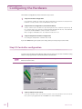
Configuring the Hardware
The Hardware Config Wizard consists of the three steps screens.
1
Step1/3 Controller configuration
2
Step2/3 Channel configuration (Customize model ID)
For setting the number of control unit, and the impedance measurement unit (when the
PFX2211 is used), and to select the USB driver to be used.
Set the channel to be used for the specified system of the controller respectively. All
the channels which are currently recognized will be displayed in the list. The maximum
channel for the Basid Edition can be used for 2 channels.
When using the PFX2500 series, the model ID needs to be set.
3
Step3/3 Temperature chamber configuration
For setting the temperature chamber to be used.
If you click Cancel during the operation, the setting of the present Step may become invalid.
Step1/3 Controller configuration
To activate the "Hardware Config Wizard", double click the short-cut icon of the "Hardware Config
Wizard" in the program folder or the desktop folder of the Windows.
When under operation of the "Test Executive", the "Hardware Config Wizard" can not be activated.
Finish the "Test Executive".
1
16
Set the number of control units.
Select the number 1 when it is set for one system, select the number 2 when it is set for
two systems (only applied for the PFX2000 series with Full Edition).
BPChecker2000
Configuring the Hardware
When using the impedance measurement unit (only for the Full Edition), click for
the check box of the assigned system.
3
Click Next.
Displays the Step 2/3 Channel Configuration.
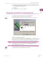
Step2/3 Channel configuration (Customize model ID)
2
Set Up
2
The maximum number of channels that can be used on the Basic Edition is 2.
When using the PFX2500 series, the model ID needs to be customized.
See
p. 19
If the "!" mark is appeared in front of the header, it is required the model ID to be updated.
Header Node number
Instrument ID
When configuring new channels
Select the system of controller configured by the Configuration On, and click Search. All the data
including present channel configuration, group and channel assignments, and the progress status
of the test will be lost, and the channel connecting to the selected controller will be displayed.
When serch is carried out, all the data including the current channel configuration, group and
channel assignments, and the progress status of the test are lost. Use extra caution when
performing this procedure. To add or delete channels, use the Add or Delete. In this case, the
existing configuration information is retained.
See
p. 15
BPChecker2000
In case the USB driver is not installed properly, the error message (I/O error of the PFX controller)
will be displayed. Confirm that the USB driver is properly installed.
17
Configuring the Hardware
When adding channels
Click Add. The Add Channel dialog box appears. Enter the node number of the channel module to
be added and click Add.
When using PFX2500 series, the model ID needs to be customized.
When deleting channels
Select the channels you wish to delete, and click Delete. You can select multiple channels at once.
Customize Model ID's (only for the PFX2500 series)
For the system with the PFX2500 series, the model ID is varied depends on configuration of the
connected DC power supply and the electronic load.
The model ID for the PFX2500 series is set at "5101" as a factory default settings of which system
configuration consists of the PFX2511, PWR800L, and PLZ1004W(H range). Therefore, when the
BPChecker2000 is installed, it is required to customize the model ID using "Hardware Config
Wizard".
1
18
Model ID
Configuration of the PFX2500 series.
5101
PFX2511, PWR800L, PLZ1004W (H range)
5102
PFX2511, PWR800L, PLZ1004W (M range)
5103
PFX2511, PWR1600L, PLZ1004W (2 units parallel)
5104
PFX2511, PWR800L, PLZ334W (H range)
5106
PFX2511, PWR1600L, PLZ1004W (H range)
5107
PFX2511, PAS10-70, PLZ1004W (H range)
5108
PFX2511, PAS20-36, PLZ1004W (H range)
5109
PFX2511, PAS20-54, PLZ1004W (H range)
5110
PFX2511, PAS40-27, PLZ1004W (H range)
5111
PFX2511, PWR800L, PLZ164W (H range)
5112
PFX2511, PAS10-35, PLZ334W (H range)
Click Customize Model ID.
Displays the Customize Model ID.
BPChecker2000
Configuring the Hardware
2
Set Up
Displays the Model ID and
the system configuration.
Select the Model ID.
Displays the channel and the
present setting.
Select the channel that you
wish to change.
2
3
Select the Model ID.
4
Click Customize Now.
Select the channel for customizing the Model ID.
You can select multiple channels at once.
When the dialog box Run As is displayed, select the Current User. Do not select the
check box of the Protect my computer and data from unauthorized program activity,
then click OK.
When the dialog box "User Account Control" is displayed, select Allow.
The information of the Model ID will be transmitted to the channel of the assigned
PFX2500 series and it becomes to be customized. The Model ID display of the channel
will be also changed.
5
When setting the different Model ID numbers for the multiple channels, repeat
the Step 2 through step 4 . When customizing the Model ID's are completed, click
Close.
When the mark "!" appears in front of the header;
When the information for the Model ID of the BPChecker2000 becomes older due to the version
upgrade, the mark "!" appears in front of the header. In such a case, customize the Model ID to be
updated. Once the Model ID has been updated, the mark "!" is changed to the "Check mark".
When the setting is completed…
When the configuration of channels is completed, click Next. The "Step 3/3 Chamber
Configuration" will be displayed.
BPChecker2000
19
Configuring the Hardware
Step3/3 Temperature chamber configuration
In case the temperature chamber is not used;
1
Set the number of temperature chamber at "0".
2
Click Finish.
A value of 0 means that the temperature chamber is not used.
The configuration of hardware has been completed. The "Hardware Config Wizard" is
finished.
In case the temperature chamber is used;
See
1
Set the number of temperature chambers.
2
Set the "Chamber Driver", a driver software for the temperature chamber.
3
Set the "VISA Resource".
p. 12
It can be set up to 6 units. In case the temperature chamber is used, the VISA library
must be installed in the PC.
Select the driver software for the temperature chamber. Currently, Tabai is supported.
Specify the COM number of the serial port.
Example) For serial port COM1: Select ASRL1::INSTR.
20
4
When you wish to control the humidity, select for the Control Humidity.
5
6
Set the Temperature Margin and the Humidity Margin.
If the Control Humidity is not selected, it is limited to control for the temperature only.
Click Finish.
The configuration of hardware has been completed. The "Hardware Config Wizard" is
finished.
BPChecker2000
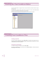
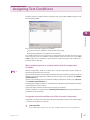
Creating Test Conditions
This chapter describes the Test Condition Editor
and the procedure for creating test conditions.
Starting the Test Condition Editor
The Test Condition Editor is a program used to create and edit all test conditions related to charge/
discharge tests.
To start the Test Condition Editor, double-click the shortcut icon of the Test Condition Editor
program from the Windows desktop folder or program folder.
You can also start the program from the Group menu of the Test Executive program.
Creating Test Conditions Files
Creating a new file
To create a new test conditions file, choose File > New. The condition of the program when it is
started is the same as when the Test Condition Editor is first started from the shortcut icon. The test
conditions file name is shown as Untitled.
Changing an existing file
To change an existing test conditions file, choose File > Open.
If you save the modified file to a separate file by selecting File > Save As, a new file diverted from
the existing file can be created.
22
BPChecker2000
Before entering the data of the test conditions
The contents that are edited using the Test Condition Editor include several items other than those
that actually concern the test conditions. The editable contents are grouped into the following
categories.
• Module
• Comment
• Battery information
• Protections
• Recording Method
• Life Judgement
• Sequence
• Sequence sheets
• Impedance Measurement (only when using the PFX2011/PFX2021)
p. 55
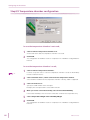
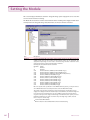
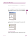
Description of the display
The Test Condition Editor takes on a window layout similar to Windows Explorer. Selecting an item
on the left side of the screen (Item Pane) switches the right side of the screen (Form Pane). The
contents of the Form Pane vary depending on the selected item.
Creating Test Conditions
See
3
Save the file when the setting of test conditions are completed.
Form Pane
Item Pane
Showing the input range
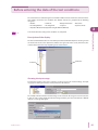
For items that require a value to be entered in a text box such as the nominal voltage, the input
range appears when you move the mouse pointer over the text box.
The example indicates that the nominal voltage can be entered in the range of 0.0000 V to 60.0000
V. You can enter a value outside the indicated range, but when you select an item from a different
item pane, a message will appear.
BPChecker2000
23
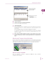
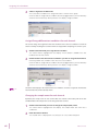
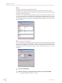
Setting the Module
This screen displays information about the charge/discharge power supply unit to be used. The
screen is used to enter basic settings.
The Model ID selected here and the actual model ID of the module (power supply module that is
actually used in the charge/discharge test) must match, or the test cannot be executed.
Item
Description
Model ID
Set the model (Model ID) of the power supply module you plan to use. When it is set, the
suitable input range for the current and the voltage setting can be presumed. The
appropriate input ranges are also used to check the range of values entered for other
items that specify the actual charge/discharge conditions.
Normally, the selectable models are as follows
Model ID
1
21
5101
5102
5103
5104
5106
5107
5108
5109
5110
5111
5112
Model
PFX2011
PFX2021
PFX2511 (PFX2511, PWR800L, PLZ1004W (H range) )
PFX2511 (PFX2511, PWR800L, PLZ1004W (M range) )
PFX2511 (PFX2511, PWR1600L, PLZ1004W (2 units parallel) )
PFX2511, PWR800L, PLZ334W (H range)
PFX2511, PWR1600L, PLZ1004W (H range)
PFX2511, PAS10-70, PLZ1004W (H range)
PFX2511, PAS20-36, PLZ1004W (H range)
PFX2511, PAS20-54, PLZ1004W (H range)
PFX2511, PAS40-27, PLZ1004W (H range)
PFX2511, PWR800L, PLZ164W (H range)
PFX2511, PAS10-35, PLZ334W (H range)
On some special-order specifications of the BPChecker2000 systems, you may be able to
select Model IDs that are not usually selectable. Select the Model ID carefully.
The outline of the electrical specification of the selected charge and discharge power
supply unit is displayed under the model ID. If you select PFX2011, the values for high and
low current ranges are displayed. You can select different ranges for the high and low
ranges for each cycle or for charge and discharge even within the same cycle. If you select
PFX2021or PFX2500 series, values are shown only in the high range column, because
there is only one current range.
Use This Model ID As Default
When clicked, the selected Model ID becomes the default setting.
24
BPChecker2000
Setting the Module
Description
Enable AutoFine
(PFX2000 series
only)
The auto fine function is enabled if the checkbox is selected.
The auto fine function brings the current value set by the constant current operation and
the current that actually flows closer together through automatic adjustment. You can
eliminate the error caused by the accuracy of the constant current setting by enabling this
function. This function is effective when you need higher accuracy of constant current
performance or when you wish to suppress the current error between channels.
As for the PFX2500 series, the "Auto fine" is always valid.
Enable DUT
Connection
Check
The connection check function of the DUT (device under test) is enabled if the checkbox is
selected.
The connection check function is to measure the voltage value on each of the output
cable and the voltage sensing wire, and if there is any dirrerence in measured voltage
value, this function determine the status as abnormal connection and an alarm occurs.
The connection check function activates immediately before the charge or discharge
operation is begun.
The measurement of voltage between the output cable and voltage sensing wire requires
time (PFX2011 and PFX2021: approx. 50 ms, PFX2511: approx. 200 ms). During this period,
if the voltage of the DUT varies (the rest time is set to short time, etc.), it may cause
generation of the alarm even when the connection is wired properly. In such case, please
disable the connection check function.
Voltage measurement
of the voltage sensing wire
Voltage measurement
of the output cable
PFX2511: Approx. 200 ms
PFX2011/ PFX2021: Approx. 50 ms
3
Creating Test Conditions
Item
Specified Voltage (Reference)
PFX2011: 3 mV
PFX2021: 30 mV
PFX2511: 100 mV
DUT voltage
It becomes an alarm state when the value
is more than the specified voltage.
The connection check function is not a function to verify the wiring condition completely
for which might be the case of difficult judgement such as connection failure.
BPChecker2000
Moving Average
Select the moving average value. You can decrease the fluctuation of the measured value
even further by performing moving average.
The processing of moving average caan be performed even at the time of Pulse discharge.
When the setting of the width of pulse time is long and the other than OFF is selected, the
measurement result will take time to be up-dated.
Num of OP01PFX boards to use
(only for the
PFX2500 Series)
When OP01-PFX option boards are installed in the PFX2500 Series, select the number of
boards that are installed.
If no boards are installed, select 0.
If you select 1 or greater, the cell voltage test is enabled.
25
Enter the comment
This screen is used to enter the date, the name of the operator, and notes.
Item
Description
Date
Enter the date directly or click the arrow on the right and use the date picker (calendar
screen used to enter the date) that appears.
Input format: dd/mm/yyyy or some similar format (The actual input format of the date
depends on the Windows region setting.)
Operator
Enter the name of the operator. You can enter up to 63 characters.
Notes
Enter an arbitrary note or comment. You can enter up to 255 characters.
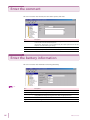
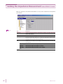
Enter the battery information
This screen is used to enter information concerning the battery.
See
26
p. 58
Item
Description
Sample Name
Enter the name of the DUT (battery). You can enter up to 63 characters.
Nominal Voltage
Enter the nominal voltage of the DUT.
Nominal Capacity
Enter the nominal capacity of the DUT. The nominal capacity is used as a reference when
setting OAH (overcharge capacity protection). Enter an appropriate value.
Volume
Enter the volume of the DUT.
Weght
Enter the weight of the DUT.
BPChecker2000
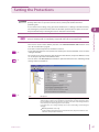
Setting the Protections
This function is used to prevent serious accidents such as damages to or explosion of the DUT
(battery). Unless there is a special reason not to do so, use this protection function when
performing tests.
In case of the incorrect setting, it may generate the trouble such as a damage to the DUT caused by
not activating the protection function under the abnormal operation (when it requires to activate
the protection function), or aborting the test even detected no abnormality.
You must set software protection to protect the DUT (battery). If you do not set appropriate values,
alarms and warnings will occur frequently, and you will not be able to execute the tests.
This screen is used to set the software protection. The "HARDWARE PROTECTION" function can be
set in the "Test Executive" program.
Each item is enabled only when the checkbox is selected.
See
p. 24
For the protection function "Conn (activates the alarm by the unconnected DUT)" can be set in the
"Setting the Module".
3
Creating Test Conditions
CAUTION
The "Shock_Det. (activates the alarm detecting by the hard vibration, only for the PFX2500 series)"
can be set by the dip switch of the PFX2500 series.
See
p. 31
See
p. 58
You can set the cells' OVP, OCP, OTP, and unbalance protection functions in the "Cell Voltage/Temp
settings" under Test Conditions.
Item
Description
OVP
Set the software OVP (overvoltage protection). If battery voltage exceeds the OVP value
during testing, an alarm occurs and the test is aborted. The accurate overvoltage detection is possible because of the detection accuracy is the same as the voltage measurement accuracy. The detecting speed is 150 ms (max).
In normal cases, set a voltage relatively close to the cutoff voltage or CV voltage for
charging.
OVP delay (PFX2500 series only)
Set the activation delay time for the protection function. (the period of time to start
activation of the protection function )
BPChecker2000
27
Setting the Protections
Item
Description
UVP
Set the software UVP (undervoltage protection). If battery voltage falls below the UVP
value during testing, an alarm occurs and the test is aborted. The accurateundervoltage
detection is possible because of the detection accuracy is the same as the voltage measurement accuracy. The detecting speed is 150 ms (max).
In normal cases, set a voltage relatively close to the cutoff voltage for discharging.
UVP delay (PFX2500 series only)
Set the activation delay time for the protection function. (the period of time to start
activation of the protection function )
OAH
Set the software OAH (overcharge capacity protection). If battery capacity exceeds the
OAH value during charge testing, an alarm occurs and the test is aborted. The value is a
percentage with respect to the nominal capacity [mAh] that was entered in Battery Info.
Set an appropriate value when performing overcharge or overdischarge tests.
OTP
Set the software OTP (overtemperature protection). If battery temperature exceeds the
OTP value during testing, an alarm occurs and the test is aborted.
Specify an appropriate value by taking the temperature measurement error and
ambient temperature fluctuation into consideration.
If the temperature measurement is not required (including the case for not connecting
the thermistor), invalid the OTP protection function.
OCP (Automatic)
Set either valid or invalid of the Software OCP (Over Current Protection) function.
The OCP value is set at +100 mA (+10 mA when set in the Low Range) of the constant
current setting value for the PFX2000 series, and +1 A of the constant current setting
value for the PFX2500 series.
When the charge current exceeds the OCP value during the test (detected by the AC
converter), the alarm will be activated and abort the test.
OCP delay (Valid only for the PFX2500 series)
It sets the activation delay time for the protection function. (the time to start
activation of the protection function )
28
BPChecker2000
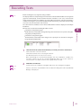
Setting the Recording Method
This screen is used to set the recording method of the charge/discharge data file that the Test
Executive creates. You can select one or more items.
Each item is enabled only when the checkbox is selected. Charge/discharge data will not be
recorded, if all items are not selected.
Creating Test Conditions
3
See
p. 58
BPChecker2000
Item
Description
Delta Time
Set the time interval for recording the data. If a short time is specified, the amount of
data that is recorded increases. If the test period is long (several hours or more), the
number of data points becomes greater than 1 000 points. Use caution when setting the
time.
When the period of testing time is long, it is convenient to use the "Auto Delta Time"
which limits the total volume of the data. While the "Auto Delta Time" is selected, the
Delta Time can not be set.
Auto Delta Time
Set the maximum number of data for recording.
Calculated by dividing the maximum test period of each phase (the time when the test is
performed as scheduled without early termination including the pause section) by the
"maximum number of data points."
If Delta Time is selected, Auto Delta Time cannot be selected.
Delta Voltage
Data is recorded when the voltage changes by an amount greater than the specified
value.
Delta Current
Data is recorded when the current changes by an amount greater than the specified
value.
29
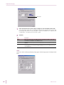
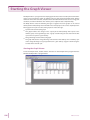
Setting the Impedance Measurement (when PFX2211 is used)
When the impedance measurement unit PFX2211 is used, set the condition for the impedance
measurement.
See
30
p. 58
Item
Description
Frequency
Set the measurement frequency. The frequency is fixed to 1000 Hz in the current
version of the software.
Range
Select the measurement range.
Auto Range
The auto range function is enabled if the checkbox is selected. Once the Auto range
function becomes valid, whenever it is required, the range will be switched automatically from the position of the selected range.
Measure Immediately
After
Specify the point in the test execution cycle when impedance measurement is to be
carried out. It is possible to select multiple measurement points. It measures the
selected items.
Charge
Measures immediately after charge is complete.
Charge Rest
Measures immediately after charge rest is complete.
Discharge
Measures immediately after discharge is complete.
Ddischarge
Rest
Measures immediately after discharge rest is complete.
BPChecker2000
Setting the Cell Voltage/Temp (Only on the PFX2500 Series)
This screen is used to configure the voltage and temperature measurement of the cells and their
protection functions.
See
p. 24
When you have installed OP01-PFX boards into the PFX2500 Series and selected 1 or greater for
Num of OP01-PFX boards to use in the "Module settings" under Test Conditions, this screen is
enabled.
3
Ôåòí Îï®
Creating Test Conditions
Óìïô îõíâåò ôèáô ôèå Ïа±ÐÆØ éó éîóôáììåä éî
See
p. 58
Item
Description
Volt Measurement
Select the terminal numbers of the cells that you want to measure the voltage of.
OVP
Set the software OVP.
Terminal
When the voltage of one of the selected terminals exceeds the OVP value, an alarm
occurs, and the test is aborted.
OVP
Set the OVP value.
Delay
Set the amount of time (the delay) before the protection function begins operating.
UVP
Set the software UVP.
Terminal
BPChecker2000
When the voltage of one of the selected terminals falls below the UVP value, an
alarm occurs, and the test is aborted.
UVP
Set the UVP value.
Delay
Set the amount of time (the delay) before the protection function begins operating.
Temp Measurement
Select the terminal numbers of the cells that you want to measure the temperature
of.
OTP
Set the software OTP.
Terminal
When the temperature of one of the selected terminals exceeds the OTP value, an
alarm occurs, and the test is aborted.
OTP
Set the OTP value.
31
Setting the Cell Voltage/Temp (Only on the PFX2500 Series)
Item
Description
Enable Unbalance
Protection Function
If you select this check box, an alarm occurs when the unbalance voltage exceeds
the unbalance margin.
The multiple cells that you have specified for voltage measurement (the OVP and
UVP terminals that you have selected) are compared, and the difference between
the maximum and minimum cell voltages is the unbalance voltage. The unbalance
voltage is detected approximately 1 second after the cell voltage measurement
completes. If the charge / discharge voltage fluctuates greatly (the internal voltage
of the DUT is high), this function may not operate correctly. If the measured voltages
are different or sensing cables are not connected to both ends of the cells, this
function will not operate correctly. For information on how to connect the cells to
the PFX2500 Series, see the PFX2500 Series operation manual.
Unbalance
Margin
Set the unbalance margin.
Enable batch setting for If you select this check box, you can set one terminal, and those settings will be
all terminals
applied to all other terminals.
32
BPChecker2000
Setting the Life Judgement
Battery capacity degrades or its impedance increases as batteries are repeatedly charged and
discharged. This screen is used to set the life judgement items.
The life judgement function determines the performance degradation of the battery by comparing
the actual capacity against the nominal capacity. When the PFX2211 is used, it can also judge the
performance failure of the battery by referring the impedance value.
3
Creating Test Conditions
This function terminates the test in the same manner as when the test is normally completed if it
determines that the battery has reached the end of its life.
See
p. 59
Item
Description
Do Capacity Rate
Judgement
If this checkbox is selected, the function determines that the battery has reached
the end of its life when the measured capacity falls below the specified
percentage (minimum capacity rate value) of the nominal capacity.
Min Capacity
Rate
The minimum capacity rate can only be specified for discharge. The reference
capacity value is the nominal capacity [mAh] that was entered in "Battery Info"
which is taken to be 100%.
Do Impedance
Judgement (when the
PFX2211 is used)
If this checkbox is selected, the function determines that the battery has reached
the end of its life when the measured impedance exceeds the specified
impedance.
Max Impedance
Max NG Count
BPChecker2000
The maximum impedance can be specified independently for charge and
discharge. The maximum impedance is evaluated on all measurements that were
specified in "Impedance Measurement."
Specify the number of failures for terminating the test. For example, if you specify
a value of 9, the test is terminated when the function determines that the battery
has reached the end of its life nine times.
33
Setting the Sequence
Sequence defines how to execute the charge/discharge contents that are specified in sequence
sheets #1 to #20. The "Test Executive" performs the charge and discharge test complied with the
description of the setting sequence.
"Repeat" specifies the number of times a sequence sheet is repeated; "Loop" specifies the number
of times the set of sequence sheets (all 20 types) are repeated. The test is performed in order from
sequence sheet #1.
34
BPChecker2000
Setting the Sequence
Description
The "Common Sequence Template" is a function that is necessary only when controlling
temperature chambers.
The BPChecker2000 can manage separately for the setting of the sequence related
function and the temperature chamber related function (including for the repeated
sequence function). The setting of the temperature chamber related function can be
shared between the multiple test condition files.
See
p. 56
Use Common Sequence Info
Select it when the "Common Sequence Template" is used. Set the file name of the
"Common Sequence Template" for the sequence information.
Test Sequence
The test is executed according to the sequence specified here. 20 types (#1 to #20) of
test sheets of charge and discharge can be specified. You can repeat any of these sheets
and loop the entire sequence. By using the sheet dedicated to predischarge (also
referred to as sheet #0), you can perform predischarge.
Repeat
Set the number of times to execute the corresponding sequence sheet. If you specify 0,
the sequence sheet is skipped.
Record
Specify whether to record the C/D data (charge/discharge data) at the test cycle.
Record (data file) remains only if the checkbox is selected. Since the last cycle when the
entire test is finished or aborted must be saved, C/D data file is created once even if
Record is disabled. The file is automatically deleted when the relevant cycle is no longer
the last cycle (when the data for the next cycle is created).
Loop
Set the number of times to repeat the test consisting of sequence sheets #1 to #20.
Perform Startup
Predischarges
3
Creating Test Conditions
Item
Common
Sequence
Template
When it is selected, it starts to perform the Startup Predischarge.
Startup predischarge refers to discharge that is carried out before the execution of the
first cycle when a new test is started or when the test is aborted and restarted.
When performing the Startup Predischarge, specify the description of the Predischarge.
Use Predischarge Sheet
For the Startup Predischarge, use the Predischarge sequence sheet (Sequence sheet
#0).
Use Discharge Sheet of Previous Cycle
The discharge sheet of the sequence sheet that corresponds to the cycle previous to
the restart cycle is used.
For the setting of "Startup Predischarges", when the "Do Predischarge when the sheet is
first used" is selected for the Charge sheet of each sequence sheet, the setting on the
sequence sheet takes priority (the sequence #0 is used)
Set Chamber When This setting is enabled when the test is executed using the temperature chamber
synchronization.
Finished/Aborted
If the checkbox is selected, the temperature and humidity of the temperature chamber
specified on the sequence sheet can be reset to the values specified here when the test
is finished or aborted.
BPChecker2000
Temperature
Set the temperature at the time when the test is finished or when the test is aborted.
Humidity
Set the humidity at the time when the test is finished or when the test is aborted.
When setting the humidity, check the control range of the temperature and humidity of
the temperature chamber being used. Depending on the performance of the
temperature chamber, some humidity ranges may not be possible against the specified
temperature. In such case, specify -1 and the humidity control will be disabled.
35
Setting the Sequence
Relationship between the predischarge settings and discharge sheets that are executed
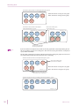
The following describes how the predischarge performs by the setting of the predischarge, the case
is an example for the sequence setting of that the sheet #1 and #2 are only used. There are twelve
patterns in the predischarge setup pattern that you can set by using two sequence sheets.
As for the sequence setting, the "Repeat" is set for 2 (Sequence sheet #1), for 1 (Sequence sheet #2),
for 0 (Sequence sheet #3 to #20), and the "Loop" is set for 2.
1
Predischarge setup pattern
2
3
4
5
6
7
8
9
10
11
12
Execute startup discharges
Use Predischarge Sheet
Use Discharge Sheet of Previous Cycle
Do Predischarge when the sheet is first used
Sequence sheet
#1
Sequence sheet
#2
■ Case 1: The case when the specified sequence finished normally.
Test start
Predischarge
Cycle
1
Cycle
2
-
#0
-
#0
#0
#0
Sequence sheet
#0
#0
#1
Sequence sheet
Predischarge
-
-
#0
#0
-
-
#0
#0
#0
#0
-
-
#0
#0
#1
#0
#0
Sequence sheet
#2
Cycle
3
Cycle
4
Sequence sheet
#1
Cycle
5
Sequence sheet
#1
Cycle
6
Sequence sheet
#2
For patterns 6 and 8, there is a conflict in the predischarge settings is started between the sequence
sheet setting and the sheet #1 setting. In this case, the setting of sheet has priority, and
predischarge is never executed twice. For patterns 9 to 12, Use Discharge Sheet of Previous Cycle is
selected. This case specifies immediately after starting the test, so there is no previous cycle. The
result is the same as when Use Predischarge Sheet is selected.
■ Case 2: The case when the test is aborted at cycle 3 of the specified sequence and
then restarted.
Test start
Predischarge
Cycle
1
Cycle
2
Predischarge
Cycle
-
#0
-
#0
#0
#0
Sequence sheet
#0
#0
#1
Sequence sheet
-
-
#0
#0
3
-
-
#0
Sequence sheet
#0
#0
#0
#0
-
-
#0
#0
#1
#1
#0
#0
#1
#0
#2 Abort
Test restart
#0
#0
Cycle
3
Sequence sheet
#2
Cycle
4
Sequence sheet
#1
Cycle
5
Sequence sheet
#1
Cycle
6
Sequence sheet
#2
Predischarge
-
-
#0
#0
#0
#0
Since a test is restarted from the aborted cycle. The sequence sheet that is used first when the test is
restarted is the sheet that was being used when the test was aborted. However, the trace that the
sheet was used is lost when the test is aborted. The case 2 is specified that restarts from the "Cycle
3", and the sheet #2 is used for the first time. If the Do Predischarge when the sheet is first used
checkbox of sequence sheet #2 is selected, the predischarge sheet is reused as shown in
predischarge setup patterns 3, 4, 7, 8, 11, and 12.
Use Predischarge Sheet is selected in patterns 5 and 6. Thus, predischarge is executed when the
test is restarted.
Use Discharge Sheet of Previous Cycle is selected in patterns 9 and 10. Thus, predischarge is
executed using sequence sheet #1 when the test is restarted.
36
BPChecker2000
About Sequence Sheet
There are 21 sequence sheets including the predischarge sheet and sheets #1 to #20. Since each
sheet from #1 to #20 consists of a charge condition sheet and a discharge condition sheet, the total
number of sheets is 41.
For the test condition of charge and discharge, click the view tab to change the condition sheet.
Fo the charge or discharge condition, the setting descriptions are varied by the operation mode.
Each operation mode for the charge test, predischarge test, and discharge test are described in the
following section.
3
Creating Test Conditions
Click the tab to change the
condition sheet.
When you click Copy from or Copy to, the descriptions of other sequence sheet can be copied or
pasted.
BPChecker2000
37
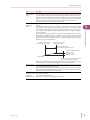
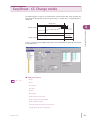
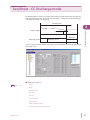
Seq Sheet - CC-CV Charge mode
The following figure is shown as an example of the Constant Current and the Constant Voltage (CCCV) charge operation. The figure illustrates the transition of constant current charge -> constant
voltage charge -> CV time -> charge rest. (In this example, charge is complete when CV time is
reached.)
Charge time
CV time
Battery voltage
CV voltage
Charge current
It time
Rest time
It current
Select 1 or greater for "Num of OP01-PFX boards to use" under Module to display the Cell Voltage/
Temp Setup screen.
■ Setting descriptions
See
p. 43、p. 60
Range
Mode
Charge Time
Rest Time
Current
CV Voltage
CV Time
Enable IT Functionality
Enable Chamber Control
Do Predischarge when the sheet is first used
Cell Voltage/Temp (for cut conditions)
38
BPChecker2000
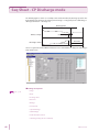
Seq Sheet - CC Charge mode
The following figure is shown as an example of the Constant Current (CC) charge operation. The
figure illustrates the transition of constant current charge -> -dV detection -> charge termination ->
charge rest.
Charge time
Maximum voltage
-dV
Rest time
Charge current
Select 1 or greater for "Num of OP01-PFX boards to use" under Module to display the Cell Voltage/
Temp Setup screen.
3
Creating Test Conditions
Battery voltage
■ Setting descriptions
See
p. 43、p. 59
Range
Mode
Charge Time
Rest Time
Current
Max Voltage
Enable Delta-V Functionality
Enable Temperature Functionality
Enable Chamber Control
Do Predischarge when the sheet is first used
Cell Voltage/Temp (for cut conditions)
BPChecker2000
39
Seq Sheet - Pulse Charge mode (PFX2000 series only)
The following figure is shown as an example of the Pulse charge operation. In pulse charge,
charging is performed over three periods: constant current charge (CC), constant current/pulse
charge (CC-Pulse), and PWM pulse charge (PWM).
constant current charge → maximum (transition) voltage detection → constant current/pulse
charge → maximum (transition) voltage → Pulse ON current → Pulse OFF current → minimum
voltage detection → It time → charge rest.
(when the period from pulse OFF to minimum
voltage detection is less than or equal to It time)
Charge time
PWM time
Battery
voltage
Maximum
voltage
Maximum
voltage
Constant
current
CC period [1]
40
Pulse
current 1
Maximum voltage
ON time
Pulse time 1
Pulse time 2
Charge
current
Minimum voltage
It time
Pulse
current 2
CC-Pulse period [2]
Pulse ON current
Pulse OFF current
Rest time
PWM period [3]
BPChecker2000
Seq Sheet - Pulse Charge mode (PFX2000 series only)
■ Setting descriptions
See
p. 43、p. 60
Range
Mode
CC Period [1]
CC-Pulse Period [2]
PWM Period [3]
3
Charge Time
Creating Test Conditions
Rest Time
Enable Chamber Control
Do Predischarge when the sheet is first used
Current control during the PWM period
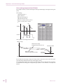
Current control during the PWM period varies depending on the Max Voltage (OFF voltage)
setting.
When the Max Voltage (OFF voltage) check box is selected
When the battery voltage increases to the OFF voltage or when the ON time elapses during the ON
current period, the operation moves to OFF current. During the OFF current period, the operation
moves to ON current when the battery voltage drops to the ON voltage and the OFF time has
elapsed. Because voltage detection requires at least 0.5 ms, the minimum ON current time is 0.5 ms.
Max. voltage (OFF voltage)
Min. voltage (ON voltage)
ON current
ON time
OFF time
OFF current
PWM period
BPChecker2000
41
Seq Sheet - Pulse Charge mode (PFX2000 series only)
PWM charge period start
The relationship of the current ON/OFF time
The actual current ON time ≤ ON time
The actual current OFF time ≥ OFF time
ON current
Increase up to the
OFF voltage
Yes
No
No
ON time has elapsed
Yes
OFF current
OFF current
Increase up to the
OFF voltage
Yes
Clear the OFF time counter
No
No
OFF time has elapsed
Yes
No
OFF time has elapsed and
dropped to the ON voltage
Yes
When the Max Voltage (OFF voltage) check box is not selected
When the ON time elapses during the ON current period, the operation moves to OFF current.
During the OFF current period, the operation moves to ON current when the battery voltage drops
to the ON voltage and the OFF time has elapsed.
Min. voltage (ON voltage)
ON current
ON time
OFF time
OFF current
PWM period
PWM charge period start
ON current
No
The relationship of the current ON/OFF time
The actual current ON time = ON time
The actual current OFF time ≥ OFF time
ON time has elapsed
Yes
OFF current
No
OFF time has elapsed and
dropped to the ON voltage
Yes
42
BPChecker2000
The Setting Description for the Charge Conditions
Description
Range
You can select the range if you selected the PFX2011 Charge/Discharge Power Supply
Unit for Model ID in "Module." Depending on the range selection, the valid ranges for
settings concerning current, capacity, and power vary.
Mode
Select the charge mode. Select CC-CV, CC, or Pulse.
Other modes may be included depending on the Test Condition Editor version. Dimmed
items are not selectable.
Charge Time
Set the maximum time for a charge period. Charge Time is one of the function that
terminate charging. Charging stops after this time elapses, if it has not already been
ended by another factor. In the Pulse charge mode, when the total time of all periods
(CC, CC-Pulse, and PWM) exceeds this value, the operation terminates charging and
moves to rest. If the entry is 0:00, charge is skipped.
Rest Time
Set the state in which nothing is performed after charging is finished and before
transiting to discharging. If the entry is 0:00, rest is skipped.
Current
Set the charge current. The input range varies depending on the range setting on the
PFX2011 Charge/Discharge Power Supply Unit.
CV Voltage
Set the voltage value at which the battery voltage moves to constant voltage (CV)
operation.
CV Time
CV time is one of the factors that terminate charging. Set the time from shifting to the
constant voltage (CV) operation due to the increase of the battery voltage until the
charge is finished.
Enable It Functionality
Selecting this checkbox enables you to set It Current and It Time.
It Current
Set the It current value. It current is the current value for detecting charge current, which
may be arbitrarily set by the user when performing a constant voltage charge. After this
current is detected, charging ends once the set It time elapses. The input range varies
depending on the range setting on the PFX2011 Charge/Discharge Power Supply Unit.
It Time
It time is one of the factors that terminate charging. Set the time from detecting the It
current until the charge is finished.
Max Voltage
Set the maximum voltage. Maximum voltage is one of the factors that terminate
charging. Charging ends when the battery voltage reaches the specified value during
charging.
Enable Delta-V Functionality
Select this checkbox enables you to set -dV and -dV Mask Time.
-dV
Set the -dV. The value -dV is one of the factors that terminate charging. Charging ends
when the battery voltage drops by a value specified by -dV during charging. This
detection can be disabled during the -dV mask time.
-dV Mask Time
Set the -dV mask time. The -dV detection is disabled during the -dV mask time.
CC Period [1]
Set the CC preiod [1].
Max Voltage
Set the maximum voltage. When the battery voltage reaches maximum voltage during
CC charging, the operation moves to the CC-Pulse period.
Current
Set the charge current during the CC period.
The input range varies depending on the range setting on the PFX2011 Charge/Discharge
Power Supply Unit.
CC-Pulse Period [2]
BPChecker2000
3
Creating Test Conditions
Item
Set the CC preiod [2].
Max Voltage
Set the maximum voltage. CC-Pulse. When the battery voltage reaches maximum
voltage during CC-Pulse charging, the operation moves to the PWM period.
Current (1, 2)
Set the pulse current (1 and 2) during the CC-Pulse period.
The input range varies depending on the range setting on the PFX2011 Charge/
Discharge Power Supply Unit.
Time (1, 2)
Set the pulse time width (1 and 2) during the CC-Pulse period.
43
Seq Sheet - Pulse Charge mode (PFX2000 series only)
Item
Description
PWM Period [3]
Set the CC preiod [3].
Max Time
Set the maximum time for the PWM period. When this time elapses, the operation
moves to charge rest.
Min Voltage
Set the minimum voltage. When the battery voltages drops to minimum voltage during
pulse OFF current, the operation moves to pulse ON current.
Max Voltage
Set the maximum voltage. When the battery voltages reaches this voltage during pulse
ON current, the operation moves to pulse OFF current.
Selecting the check box enables you to set the maximum voltage. Current control
during the PWM period varies depending on the selected/unselected status of this
check box.
Current (ON,
OFF)
Set the pulse current (ON and OFF) during the PWM period.
The input range varies depending on the range setting on the PFX2011 Charge/
Discharge Power Supply Unit.
Time (ON, OFF) Set the pulse time width during the PWM period.
Current control during the PWM period varies depending on the selected/unselected
status of Max Voltage check box.
It Time
Enable Temperature
Functionality
Set the It time. When the time for detecting the minimum voltage from starting the
pulse OFF current reaches IT time, the operation moves from the PWM period to rest.
Selecting this checkbox enables you to set Max Temp and dT/dt.
Max Temp
Set the maximum temperature. Maximum temperature is one of the factors that
terminate charging. Charging ends when the battery temperature exceeds the specified
value during charging.
dT/dt
Set the dT/dt. The value dT/dt is one of the factors that terminate charging. Charging
ends when the battery temperature increases by dT/dt within a unit time (1 minute)
during charging.
Enable Chamber Control
If this item is enabled, temperature chamber settings are performed in the cycle if this
sequence sheet is used. In this case, you must also enter Temperature, Humidity, Setting
Timeout, and Wait Time.
Temperature
Specify the temperature setting of the chamber.
Humidity
Specify the humidity setting of the chamber.
Check the control range of the temperature and humidity of the temperature chamber
being used. Depending on the performance of the temperature chamber, some
humidity ranges may not be possible against the specified temperature. In such case,
specify -1 and the humidity control will be disabled.
Setting
Timeout
The temperature chamber does not reach the specified condition immediately after the
temperature and humidity are set. If the temperature chamber does not reach the target
temperature and humidity (within the range specified in system settings) even after the
specified time elapses, the setting is considered to have failed.
Wait Time
Even if the temperature chamber reaches the target temperature and humidity, you
must allow some time for the battery in the chamber to reach the temperature. This
setting specifies the wait time. If testing is performed in synchronization with the
temperature chambers, the actual charge starts after the wait time elapses.
Do Predischarge when the sheet If this item is enabled, predischarge is executed once when this sequence sheet is used
is first used
first. Predischarge sequence sheet (sequence sheet #0) is used for the predischarge. This
setting has priority if the Execute startup discharges setting that is specified on the
sequence page.
Cell Voltage/Temp
(for cut conditions)
Terminal
44
Select this check box to set the cell voltages and temperatures.
Select the terminals to set the maximum voltage or maximum temperature that will be
used as an end condition.
Max Voltage
When the maximum voltage is reached, charging is stopped.
Max Temp
When the maximum temperature is reached, charging is stopped.
BPChecker2000
Seq Sheet - Pulse Charge mode (PFX2000 series only)
Description
Enable
Unbalance
Voltage
Detection
Select this check box to set the unbalance margin.
The multiple cells that you have specified for voltage measurement (the terminals that
you have set maximum voltages for) are compared, and the difference between the
maximum and minimum cell voltages is the unbalance voltage.
Charging is stopped when the unbalance voltage exceeds the unbalance margin.
The unbalance voltage is detected approximately 1 second after the cell voltage
measurement completes. If the charge / discharge voltage fluctuates greatly (the
internal voltage of the DUT is high), this function may not operate correctly.
If the measured voltages are different or sensing cables are not connected to both ends
of the cells, this function will not operate correctly. For information on how to connect
the cells to the PFX2500 Series, see the PFX2500 Series operation manual.
Enable batch If you select this check box, you can set one terminal, and those settings will be applied
setting for all to all other terminals.
terminals
BPChecker2000
3
Creating Test Conditions
Item
45
Seq Sheet - Predischarge
Set the predischarge to execute for the case when starting the test, or when the sequence sheet is
used for the first time.
■ Setting descriptions
See
p. 53、p. 61
Range
Mode
Discharge Time
Rest Time
Capacity Voltage
Cutoff Voltage
Enable Chamber Control
Cell Voltage/Temp (for cut conditions)
46
BPChecker2000
Seq Sheet - CC Discharge mode
The following figure is shown as an example of the Constant Current (CC) discharge operation. The
figure illustrates the transition of constant current discharge -> voltage drop to the cutoff voltage > discharge termination -> discharge rest.
Discharge time
Battery voltage
Cutoff voltage
Rest time
Discharge current
Discharge current
Select 1 or greater for "Num of OP01-PFX boards to use" under Module to display the Cell Voltage/
Temp Setup screen.
Creating Test Conditions
3
■ Setting descriptions
See
p. 53、p. 61
Range
Mode
Discharge Time
Rest Time
Current
Capacity Voltage
Cutoff Voltage
Enable Chamber Control
Cell Voltage/Temp (for cut conditions)
BPChecker2000
47
Seq Sheet - CP Discharge mode
The following figure is shown as an example of the Constant Power (CP) discharge operation. The
figure illustrates the transition of constant power discharge -> voltage drop to the cutoff voltage ->
discharge termination -> discharge rest.
Discharge time
Battery voltage
Cutoff voltage
Rest time
Discharge current
Limit current
Select 1 or greater for "Num of OP01-PFX boards to use" under Module to display the Cell Voltage/
Temp Setup screen.
■ Setting descriptions
See
p. 53、p. 61
Range
Mode
Discharge Time
Rest Time
Wattage
Limit Current
Capacith Voltage
Cutoff Voltage
Enable Chamber Control
Cell Voltage/Temp (for cut conditions)
48
BPChecker2000
Seq Sheet - CC-Pulse Discharge mode
The following figure is shown as an example of the Constant Current and the Pulse (CC-Pulse) discharge operation. The figure illustrates the transition of pulse discharge -> voltage drop to the
cutoff voltage -> pulse discharge termination -> discharge rest.
Discharge time
Battery voltage
3
Rest time
Pulse
discharge current
Enlarged view
Battery voltage
Pulse
discharge current
Creating Test Conditions
Cutoff voltage
Select 1 or greater for "Num of OP01-PFX boards to use" under Module to display the Cell Voltage/
Temp Setup screen.
■ Setting descriptions
参照
p. 53、p. 62
Range
Mode
Discharge Time
Rest Time
Pulse Setting
Capacity Voltage
Cutoff Voltage
Enable Chamber Control
Cell Voltage/Temp (for cut conditions)
BPChecker2000
49
Seq Sheet - CC-Pulse Discharge mode
Pulse setting example of the PFX2021
This example is for the case when detecting the discharge cutoff voltage on the high end using two
pulses.
Pulse Settings
Number of pulses: 2
Pulse mode: CC
Measurement High: Pt1
Measurement Low: Pt2
Current 1: 2.000A, current 2: 0.500 A
Time 1: 0.50 ms, Time 2: 0.50 ms
pt2
Voltage
Current
pt1
Pulse
1
Pulse
2
Pulse operation and voltage measurement
Battery voltage
Measured pt2 voltage
(specified by Measurement Low)
Measured pt1 voltage
(specified by Measurement High)
Discharge finished
Discharge
cutoff voltage
Charge operation
If you set Measurement High to "High," the voltage of Pt2 is retrieved. The data is the same as the
measured voltage of Measurement Low, and the graphs overlap.
The sampling interval of the pulse voltage varies depending on the specified pulse time. For details,
see "Measurements during pulse charge/discharge operation" in the PFX2000 Series Operation
Manual.
50
BPChecker2000
Seq Sheet - CP-Pulse Discharge mode (except the PFX2011)
You can select the CP-Pulse discharge if you selected the PFX2021 or PFX2500 series for "Module >
Model ID."
The following figure is shown as an example of the Constant Power and the Pulse (CP-Pulse)
operation. The figure illustrates the transition of constant power pulse discharge -> voltage drop to
the cutoff voltage -> pulse discharge termination -> discharge rest.
3
Creating Test Conditions
Discharge time
Battery
voltage
Cutoff voltage
Limit current
Pulse
discharge
current
Rest time
Enlarged view
Select 1 or greater for "Num of OP01-PFX boards to use" under Module to display the Cell Voltage/
Temp Setup screen.
BPChecker2000
51
Seq Sheet - CP-Pulse Discharge mode (except the PFX2011)
■ Setting descriptions
See
p. 53、p. 62
Range
Mode
DIscharge Time
Rest Time
Pulse Setting
Limit Current
Capacity Voltage
Cutoff Voltage
Enable Chamber Control
Cell Voltage/Temp (for cut conditions)
Update time
In CP-Pulse discharge, the discharge current is controlled by software computation. The settling
time (update time) from the voltage measurement by the ADC to the computation and the
assignment of the discharge current is constant (2 ms typ.), independent of the pulse time width.
52
BPChecker2000
The Setting Descriptions for the Discharge Conditions
Description
Range
You can select the range if you selected the PFX2011 Charge/Discharge Power Supply
Unit for Model ID in "Module."
Depending on the range selection, the valid ranges for settings concerning current,
capacity, and power vary.
Mode
Select the mode. Select CC, CP, or Pulse.
To select CC-Pulse or CP-Pulse, select Pulse and then select CC or CP for Pulse Mode of
Pulse Setting.
Other modes may be included depending on the Test Condition Editor version.
However, they are for special-order features. Dimmed items are not selectable.
Discharge Time
Set the discharge time. The discharge time is one of the factors that terminate
discharging. Discharging ends when this discharge time elapses. If the entry is 0:00,
discharge is skipped.
Rest Time
Set the time after discharging has ended (state in which nothing is performed after
discharging). If the entry is 0:00, rest is skipped.
Current
Set the discharge current. The input range varies depending on the range setting on the
PFX2011 Charge/Discharge Power Supply Unit.
Wattage
Set the discharge wattage value. The input range varies depending on the range setting
on the PFX2011 Charge/Discharge Power Supply Unit.
Limit Current
Set the limit current. In constant power discharge, the discharge current increases as the
battery voltage drops. The limit current value is the upper limit value for the discharge current.
The input range varies depending on the range setting on the PFX2011 Charge/
Discharge Power Supply Unit.
Pulse Settings
Set the Pulse.
Num Of Pulse
Set the number of pulses per cycle. In the CC-Pulse discharge mode, you can set up to 8
values on the PFX2011 and 20 values on the PFX2021 and PFX2500 series.
Pulse Mode
To select CC-Pulse mode, select CC. To select CP-Pulse mode, select CP.
Measurement
Specify the points for measuring the voltage during pulse discharging. Voltage can be
measured at two points. The discharge cutoff voltage is detected at the lower of the
measurement points, Measurement High or Measurement Low for the PFX2011 and at
the Measurement Low point for the PFX2021 and PFX2500 series.
3
Creating Test Conditions
Item
High
Select the voltage measurement point from High (Highest voltage point in the cycle)
and pt1 to ptn (n: number of pulses, Point immediately before the switching of each
current value).
Low
Select the voltage measurement point from Low (Lowest voltage point in the cycle)
and pt1 to ptn (n: number of pulses, Point immediately before the switching of each
current value).
Current
Capacity Voltage
Set each current value of pulse discharge. You can set a current value for each pulse
value.
The input range varies depending on the range setting on the PFX2011 Charge/
Discharge Power Supply Unit.
Power
Set each power value of pulse discharge. You can set a power value for each pulse value.
Time
Set each time width of pulse discharge. You can set a time width for each pulse value.
This function stops the integration of the discharge capacity when the battery voltage,
which declines as discharge progresses, falls below the capacity voltage setting.
Discharge time
Rest time
Battery voltage
Capacity voltage
Cutoff voltage
Discharge voltage
BPChecker2000
53
Seq Sheet - CP-Pulse Discharge mode (except the PFX2011)
Item
Description
Cutoff Voltage
Set the Cutoff Voltage. The cutoff voltage is one of the factors that terminate
discharging. Discharging ends when the battery voltage falls to this voltage even if
discharge time has not elapsed.
For pulse discharge, discharging is terminated when the lower of the voltage values,
Measurement High or Measurement Low, drops to the cutoff voltage for the PFX2011
and when the voltage value of Measurement Low drops to the cutoff voltage for the
PFX2021 and PFX2500 series. (On the PFX2021, if Measurement Low is set to a value
other than "Low," the cutoff voltage is not detected until the ptn voltage is measured.)
Enable Chamber Control
If this item is enabled, temperature chamber settings are performed in the cycle if this
sequence sheet is used. In this case, you must also enter Temperature, Humidity, Setting
Timeout, and Wait Time.
Temperature
Specify the temperature setting of the chamber.
humidity
Specify the humidity setting of the chamber.
Check the control range of the temperature and humidity of the temperature chamber
being used. Depending on the performance of the temperature chamber, some
humidity ranges may not be possible against the specified temperature. In such case,
specify -1 and the humidity control will be disabled.
Setting
Timeout
The temperature chamber does not reach the specified condition immediately after the
temperature and humidity are set. If the temperature chamber does not reach the target
temperature and humidity (within the range specified in system settings) even after the
specified time elapses, the setting is considered to have failed.
Wait Time
Even if the temperature chamber reaches the target temperature and humidity, you
must allow some time for the battery in the chamber to reach the temperature. This
setting specifies the wait time. If testing is performed in synchronization with the
temperature chambers, the actual charge starts after the wait time elapses.
Cell Voltage/Temp
(for cut conditions)
Select this check box to set the cell voltages.
Terminal
Select this check box to set the cutoff voltages. When the cutoff voltages are reached,
discharging is stopped.
Enable
Unbalance
Voltage
Detection
Select this check box to set the unbalance margin.
The multiple cells that you have specified for measurement (the terminals that you have
set cutoff voltages for) are compared (for pulse discharge, the measurements are taken
at the Measurement Low point), and the difference between the maximum and
minimum cell voltages is the unbalance voltage.
Discharging is stopped when the unbalance voltage exceeds the unbalance margin.
For pulse discharge, the measured values vary more than normal. Take this into account
when you configure the settings.
The unbalance voltage is detected approximately 1 second after the cell voltage
measurement completes. If the charge / discharge voltage fluctuates greatly (the
internal voltage of the DUT is high), this function may not operate correctly.
If the measured voltages are different or sensing cables are not connected to both ends
of the cells, this function will not operate correctly. For information on how to connect
the cells to the PFX2500 Series, see the PFX2500 Series operation manual.
Enable batch If you select this check box, you can set one terminal, and those settings will be applied
setting for all to all other terminals.
terminals
The PFX2021 does not detect the cutoff voltage until it measures the ptn voltage that has been set
by the cutoff voltage's Measurement Low. If you have set the Pulse Settings so that it takes a long
time for all pulses to be generated and the cutoff voltage's Measurement Low to a setting other
than "Low," discharging may continue even if the voltage falls below the cutoff voltage.
If you set Measurement Low to "Low," the cutoff voltage is always detected.
54
BPChecker2000
Saving the test conditions file
When the setting of test condition is completed, save it to the file.
To save the opened test conditions file, select File > Save or File > Save as. The extension of the test
condition file is ".BPCT".
Save the test condition file to the group folder which is recognized by the BPChecker2000.
When the saved folder is not registered as the group folder, the test can not be executed because
the folder can not be recognized as the group from the "Test Executive".
Message that appears when saving a file (Create the group folder).
When the folder saved for the test condition file is not recognized as the group folder of the
BPChecker2000, the message appears when saving a file.
3
Creating Test Conditions
For example, if a test conditions file named C:\MyFolder\MyTestCond.BPCT is created and the file is
to be used in an actual test, the folder named C:\MyFolder must be a group folder that the
BPChecker2000 system identifies.
When the folder is not recognized as the group folder, the test can not be executed, in this case,
click YES, then following dialog "Add Group" displays.
Unless there is a special reason not to do so, recommended that the same name be used for the
group name and folder name.
When creating the group folder is completed, the icon of the selected folder changes to as
and it becomes registered and controlled as a group of the BPChecker2000 system.
,
It can be recognized by the "Test Executive" program. The "Desktop.INI" is a file to manage the icon
of the folder. Do not delete this file. Do not delete this file.
■ Deleting a group
The group can be deleted by the "Group Administrator". Refer to the Help file of the "Group
Administrator".
BPChecker2000
55
Common Sequence Templete
When performing tests in synchronization with the temperature chamber, it is required that all the
channels of synchronized operation must be bound to the same group.
The general rule is to collectively assign the same test conditions to all the channels in the group
when a temperature chamber is synchronized. However, you can exceptionally mix different test
conditions in the group. The setup conditions of a temperature chamber becomes concern due to
the mixture of the different test conditions within the group. The setup conditions of a temperature
chamber is set on the charge/discharge sheets in the test conditions. If you mix different test
conditions within the same group, this results in a mixture of different setup conditions of
temperature chambers and different test sequences of charge/discharge sheets. Such discrepancy
is not allowed in temperature chamber synchronization.
The BPChecker2000 can save the file as separate file (Common Sequence Template file) for
repeating the sequence and the description of the temperature chamber settings. If you use a
Common Sequence Template file, inconsistencies in the sequence information and temperature
chamber setting information can be avoided.
The "Common Sequence Template" can be shared by multiple test condition files. It is useful when
testing at the same time for the different test conditions in the group using the same temperature
chamber, or when testing at the same time for combining the different power supply module (such
as combination of the PFX2011 and PFX2021) in the group using the same temperature chamber.
If all the synchronized channels are to use the same test conditions, there is no need to use the
common sequence template file.
When the "Common Sequence
Template" is used.
A.BPCT
B.BPCT
When the "Common Sequence
Template" is not used.
C.BPCT
D.BPCT
Common Sequence Templete
(Sequence information: repeat, temperature, and other data)
X.SI
The settings of the following items are stored in a common sequence template file.
Test Conditions > Sequence
Test Sequence
Perform Startup Predischarges
Set Chamber When Finished/Aborted
Test Conditions > Seq Sheet > Charge/Discharge
Enable Chamber Control
Do Predischarge when the sheet is first used
Creating a Common Sequence Template
See
56
p. 35
1
2
Set the test conditions you want to save in the Common Sequence Template.
In Test Conditions > Sequence, select the Use Common Sequence Info.
BPChecker2000
Common Sequence Templete
3
Enter the sequence information name (file name, using 1 to 63 characters).
4
To save the file, choose File > Save / Save As.
Characters that are improper for file names (<>.,/+- etc.) cannot be used.
Using the Common Sequence Template File
1
Create a test conditions file on which you want to use the common sequence
template file.
Create the file in the same folder (group) as the common template file to be used.
See
p. 24
See
p. 35
2
When performing the test in synchronization with temperature chamber by the
different power supply module, it is necessary to change the Model ID in Test
Conditions > Module.
3
4
In Test Conditions > Sequence, select the Use Common Sequence Info.
3
Creating Test Conditions
The Common Sequence Template file (.SI extension) is created in the same folder as
the test conditions file (.BPCT extension).
Enter the common template file name to be used.
Click the ▼ at the right of the combo box, select the sequence information names that
were saved in the past.
If test conditions that are different from the template file are specified, they are
changed to the settings of the common template file.
5
Choose File > Save / Save As to save the file.
The settings are saved (.BPCT extension). The common template file is overwritten (.SI
extension).
If you change the test conditions related to the template file after specifying the template file, the
common template file is changed to the new test conditions.
If you move the Common Sequence Template file (.SI) from the folder containing the test
conditions file or delete it, an error message is displayed when you open a test conditions file that
uses the template file. If this happens, close the test conditions file, move the template file back to
the original folder, and open the test conditions file again.
BPChecker2000
57
Range of Test Condition Settings
Battery Info
Item
PFX2011[1]
PFX2021[21]
PFX2511[5101 to 5112]
Nominal Voltage [V]
0.0000 to 5.0000
0.000 to 20.000
0.000 to 60.000
Nominal Capacity
0.1 mAh to 110000.0 mAh
←
0.0000 Ah to 2000.0000 Ah
Volume [ml]
0.01 to 99999.99
←
←
Weight [g]
0.01 to 99999.99
←
←
Protections
Item
PFX2011[1]
PFX2021[21]
PFX2511[5101 to 5112]
Software OVP [V]
0.0000 to 5.1000
0.000 to 21.000
0.000 to 63.000
Software UVP [V]
-2.1000 to 5.0000
-2.100 to 19.000
-6.000 to 57.000
OAH [%]
100 to 1000
←
←
OTP [ C]
-40.0 to 100.0
←
←
OVP delay [ms]
---
---
0 to 5000
UVP delay [ms]
---
---
0 to 5000
OCP delay [ms]
---
---
0 to 5000
Cell end conditions (only on a PFX2500 Series in which an OP01-PFX is installed)
Item
OP01-PFX
Software OVP [V]
0.000 to 21.000
Software UVP [V]
-2.000 to 19.000
OTP [ C]
-100.0 to 400.0
OVP delay [ms]
0 to 5000
UVP delay [ms]
0 to 5000
Unbalance margin [V]
0.010 to 5.000
Recording Method
Item
PFX2011[1]
PFX2021[21]
PFX2511[5101 to 5112]
Delta Time [s]
1 to 50000
←
←
Auto Delta Time Max Data
Count
1000 to 5000
←
←
Delta Voltage [V]
0.0001 to 0.9999
0.001 to 0.999
←
Delta Current [A]
0.0001 to 0.9999
0.001 to 0.999
←
Impedance Measurement
58
Item
PFX2011[1]
PFX2021[21]
PFX2511[5101 to 5112]
Frequency [Hz]
1000
←
-
Range [Ω]
0.1 / 1 / 10 / Auto
←
-
BPChecker2000
Range of Test Condition Settings
Life Judgement
Item
PFX2011[1]
PFX2021[21]
PFX2511[5101 ~ 5112]
Min Capacity Ratio Discharge
[%]
0.0 to 100.0
←
←
Charge
0 to 20000000
←
---
Discharge
0 to 20000000
←
---
1 to 100
←
←
Max NG Count
3
Seq Sheets (Charge)
■ Charge (CC mode)
The values inside parentheses are setting range for the low range.
Item
PFX2011[1]
PFX2021
[21]
PFX2511
[5101 to
5106]
PFX2511
[5107]
PFX2511
[5108]
PFX2511
[5109]
PFX2511
[5110]
PFX2511
[5111]
PFX2511
[5112]
Charge Time [h:min]
9999h 59min
←
←
←
←
←
←
←
←
Rest Time [h:min]
9999h 59min
←
←
←
←
←
←
←
←
Setting
Current [A]
0.0000 to
5.0000
(0.00000 to
0.50000)
0.000 to
10.000
0.000 to
50.000
←
0.000 to
36.000
0.000 to
50.000
0.000 to
27.000
0.000 to
50.000
0.000 to
35.000
Cutoff
conditions
Max Voltage [V]
0.0000 to
5.0000
0.000 to
20.000
0.000 to
60.000
0.000 to
10.000
0.000 to
20.000
←
0.000 to
40.000
0.000 to
60.000
0.000 to
10.000
-dV [V]
0.0010 to
1.0000
0.001 to
1.000
0.010 to
10.000
←
←
←
←
←
←
-dV Mask Time
[min]
1 to 60
←
←
←
←
←
←
←
←
Max Temp [ C]
-40.0 to 100.0
←
←
←
←
←
←
←
←
dT/dt [ C/min]
0.5 to 10.0
←
←
←
←
←
←
←
←
Creating Test Conditions
Max Impedance
[mΩ]
Cell end conditions (only on a PFX2500 Series in which an OP01-PFX is installed)
BPChecker2000
Item
OP01-PFX
Max. voltage [V]
0.000 to 20.000
Max. Temp [ C]
-100.0 to 400.0
Unbalance margin [V]
0.010 to 5.000
59
Range of Test Condition Settings
■ Charge (CC-CV mode)
The values inside parentheses are setting range for the low range.
Item
PFX2011[1]
PFX2021
[21]
PFX2511
[5101 to
5106]
PFX2511
[5107]
PFX2511
[5108]
PFX2511
[5109]
PFX2511
[5110]
PFX2511
[5111]
PFX2511
[5112]
Charge Time [h:min]
9999h 59min
←
←
←
←
←
←
←
←
Rest Time [h:min]
9999h 59min
←
←
←
←
←
←
←
←
Setting
Current [A]
0.0000 to
5.0000
(0.00000 to
0.50000)
0.000 to
10.000
0.000 to
50.000
←
0.000 to
36.000
0.000 to
50.000
0.000 to
27.000
0.000 to
50.000
0.000 to
35.000
CV Voltage [V]
0.0000 to
5.0000
0.000 to
20.000
0.000 to
60.000
0.000 to
10.000
0.000 to
20.000
←
0.000 to
40.000
0.000 to
60.000
0.000 to
10.000
CV Time [h:min]]
9999h 59min
←
←
←
←
←
←
←
←
It Current [A]
0.0000 to
5.0000
(0.00000 to
0.50000)
0.000 to
10.000
0.000 to
50.000
←
0.000 to
36.000
0.000 to
50.000
0.000 to
27.000
0.000 to
50.000
0.000 to
35.000
It Time [h:min]
9999h 59min
←
←
←
←
←
←
←
←
Max Temp [ C]
-40.0 to 100.0
←
←
←
←
←
←
←
←
Cutoff
conditions
Cell end conditions (only on a PFX2500 Series in which an OP01-PFX is installed)
Item
OP01-PFX
Max. voltage [V]
0.000 to 20.000
Max. Temp [ C]
-100.0 to 400.0
Unbalance margin [V]
0.010 to 5.000
■ Charge (Pulse mode)
The values inside parentheses are setting range for the low range.
Item
60
PFX2011[1]
PFX2021[21]
PFX2511[5101 to 5112]
Charge Time [h:min]
9999h 59min
←
---
Rest Time [h:min]
9999h 59min
←
---
CC Period
Max Voltage [V]
0.0000 to 5.0000
0.000 to 20.000
---
Current [A]
0.0000 to 5.0000
(0.00000 to 0.50000)
0.000 to 10.000
---
CC-Pulse
Period
Max Voltage [V]
0.0000 to 5.0000
0.000 to 20.000
---
Current [A]
0.0000 to 5.0000
(0.00000 to 0.50000)
0.000 to 10.000
---
Time [ms]
0.50 to 65000.00
←
---
PWM Period
Max Time [h:min] 9999h 59min
←
---
Min Voltage [V]
0.0000 to 5.0000
0.000 to 20.000
---
Max Voltage [V]
0.0000 to 5.0000
0.000 to 20.000
---
Current [A]
0.0000 to 5.0000
(0.00000 to 0.50000)
0.000 to 10.000
---
Time [ms]
0.50 to 65000.00
←
---
It Time [s]
2 to 6000
←
---
BPChecker2000
Range of Test Condition Settings
Seq Sheets (Disharge)
■ Discharge (CC mode)
The values inside parentheses are setting range for the low range.
PFX2011[1]
PFX2021[21] PFX2511
[5101]
PFX2511
[5102]
PFX2511
[5103 to
5110]
PX2511
[5111]
PFX2511
[5102]
Discharge Time [h:min]
9999h 59min
←
←
←
←
←
←
Rest Time [h:min]
9999h 59min
←
←
←
←
←
←
Setting
Current [A]
0.0000 to 5.0000
(0.00000 to 0.50000)
0.000 to
10.000
0.000 to
50.000
0.000 to
20.000
0.000 to
50.000
0.000 to
33.000
0.000 to
50.000
Cutoff
condition
Cutoff Voltage [V]
-0.5000 to 5.0000
-2.000 to
20.000
0.000 to
60.000
←
←
←
←
Measurem
ent
Capacity Voltage
[V]
-0.5000 to 5.0000
-2.000 to
20.000
0.000 to
60.000
←
←
←
←
Cell end conditions (only on a PFX2500 Series in which an OP01-PFX is installed)
Item
OP01-PFX
Max. voltage [V]
0.000 to 20.000
Unbalance margin [V]
0.010 to 5.000
3
Creating Test Conditions
Item
■ Discharge (CP mode)
The values inside parentheses are setting range for the low range.
Item
PFX2011[1]
PFX2021
[21]
PFX2511
[5101]
PFX2511
[5102]
PFX2511
[5103]
PFX2511
[5104]
PFX2511
[5106 to
5110]
PFX2511
[5111]
PFX2511
[5112]
Discharge Time [h:min]
9999h 59min
←
←
←
←
←
←
←
←
Rest Time [h:min]
9999h 59min
←
←
←
←
←
←
←
←
Setting
Wattage [W]
0.01 to 25.00
(0.001 to 2.500)
0.02 to
200.00
0.1 to
1000.0
←
0.1 to
2000.0
0.1 to
330.0
0.1 to
1000.0
0.1 to
165.0
0.1 to
330.0
Limit Current [A]
0.0000 to 5.0000
(0.00000 to
0.50000)
0.000 to
10.000
0.000 to
50.000
0.000 to
20.000
0.000 to
50.000
←
←
0.000 to
33.000
0.000 to
50.000
Cutoff
condition
Cutoff Voltage [V]
-0.5000 to 5.0000 -2.000 to
20.000
0.000 to
60.000
←
←
←
←
←
←
Measurem
ent
Capacity Voltage
[V]
-0.5000 to 5.0000 -2.000 to
20.000
0.000 to
60.000
←
←
←
←
←
←
Cell end conditions (only on a PFX2500 Series in which an OP01-PFX is installed)
BPChecker2000
Item
OP01-PFX
Max. voltage [V]
0.000 to 20.000
Unbalance margin [V]
0.010 to 5.000
61
Range of Test Condition Settings
■ Discharge (CC-Plse mode, CP-Pulse mode)
The values inside parentheses are setting range for the low range.
Item
PFX2011[1]
PFX2021
[21]
PFX2511
[5101]
PFX2511
[5102]
PFX2511
[5103]
PFX2511
[5104]
PFX2511
[5106 to
5110]
PFX2511
[5111]
PFX2511
[5112]
Discharge Time [h:min]
9999h 59min
←
←
←
←
←
←
←
←
Rest Time [h:min]
9999h 59min
←
←
←
←
←
←
←
←
Setting
Num Of Pulse
8
20
←
←
←
←
←
←
←
Current [A]
0.0000 to 5.0000
0.000 to
(0.00000 to 0.50000) 10.000
0.000 to
50.000
0.000 to
20.000
0.000 to
50.000
←
←
0.000 to
33.000
0.000 to
50.000
Power [W]
---
0.02 to
200.00
0.1 to
1000.0
←
0.1 to
2000.0
0.1 to
330.0
0.1 to
1000.0
0.1 to
165.0
0.1 to
330.0
Time [ms]
0.50 to 65000.00
←
5.0 to
65000.0
←
←
←
←
←
←
Cutoff
Cutoff Voltage [V]
condition
-0.5000 to 5.0000
-2.000 to
20.000
0.000 to
60.000
←
←
←
←
←
←
Measure
ment
Capacity Voltage
[V]
-0.5000 to 5.0000
-2.000 to
20.000
0.000 to
60.000
←
←
←
←
←
←
Number of pulse
voltage points
2
←
←
←
←
←
←
←
←
Cell end conditions (only on a PFX2500 Series in which an OP01-PFX is installed)
Item
OP01-PFX
Max. voltage [V]
0.000 to 20.000
Unbalance margin [V]
0.010 to 5.000
Temperature chamber
62
Item
PFX2011[1]
Temperature [ C]
-273.0 to 200.0
PFX2021[21]
PFX2511[5101 to 5103]
←
←
Humidity [%]
0.0 to 100.0 or -1
←
←
Setting Timeout [min]
1 to 1000
←
←
Wait Time [min]
1 to 1000
←
←
BPChecker2000
Test Execution
This chaper describes that the confirmation needs
to be taken prior to the actual test is performed,
the required setting conditions, and an instruction
for starting the actual test.
Starting the Test Executive
The Test Executive is a program that executes charge/discharge tests according to the test
conditions file that you created using the Test Condition Editor.
Before starting the "Test Executive", configure the hardware by the "Hardware Config Wizard".
■ When synchronizing with the temperature chamber …
Turn on all RS485-to-USB converters, and temperature chambers before starting the Test Executive.
The Test Executive performs control taking Num of Chambers specified on the temperature
chamber configuration screen of the Hardware Config Wizard to be the upper limit.
Starting the Test Executive
To start the Test Executive, double-click the shortcut icon of the Test Executive program from the
Windows desktop folder or program folder.
The "Test Executive" will startup with the condition of the last operation setting (connecting each
hardware, group configuration, test progress of each channel, assigning test conditions, etc.).
When starting up the "Test Executive" for the first time, the default value of the operation will be the
setting value set by the "Hardware Config Wizard, Group Administrator, Test Condition Editor".
See
p. 100
While starting up, the Test Executive program connects to the control units (1 or 2) that were
configured by the Hardware Config Wizard via the USB and initializes the channels. If the the
hardware configuration specified conditions and the actual hardware configuration differ when the
Test Executive is started, any errors may occur.
If the Test Executive detects the entire hardware configuration, the names of the detected control
units and channels appear on the Test Executive screen.
64
BPChecker2000
Before executing test
The Test Executive consists of four panes. The selected item is highlighted on the display.
Controller/
Group Pane
Channel
Pane
Chamber
Pane
Graph Result
Pane
Item
Description
Controller/Group Pane
Select Controller or Group.
To switch the view mode, click the tab at the bottom section of the Controller/Group
Pane.
Test Execution
4
Controller view mode
Organizes information according to the system of control unit connections
group view mode
Organizes information according to test execution groups
Channel Pane
This pane displays all the channels that belong to the controller or group that is
selected in the Controller/Group Pane and their execution status.
Graph Result Pane
This pane displays the following information for the channel that is selected in the
Channel Pane.
Conditions (the test conditions that are being used)
Charge graph (realtime graph)
Discharge graph (realtime graph)
Charge result
Discharge result
Cell monitor
Channels that are not being tested are not displayed.
Click the tabs at the bottom of the pane to switch the displayed contents.
Chamber Pane
Shows the temperature chamber operation.
Creating Groups
Even when performing the "Test Executive", you can select Group > Launch GroupAdministrator
and enable to create a new group or delete existing registered group.
The changes to the group binding are not immediately applied on the Test Executive screen. You
can refresh the screen by choosing View > Refresh.
BPChecker2000
65
Binding Channels to Groups
On the Test Executive, all actions concerning test execution are performed against groups or
channels bound to groups. You cannot assign test conditions to or execute tests on channels that
are not bound to any groups. Channels on which you wish to execute tests must be bound to some
group.
Simply creating groups does not bind the channels to the groups. You must first bind the channels
to a certain group.
To bind channels to a group, choose Test > Bind/Unbind Channels. A Bind To Group/ Unbind From
Group dialog box appear.
Channel list of
Controller
Channel list of
Group
Channel list of Controller
Displays all the channels controlled by the corresponding controller that are not bound to any
group.
Channel list of Group
Channels that are bound to the corresponding group are displayed. Only those channels that
can be unbound are displayed. Since channels that have test conditions assigned to them and
are in a monitor loop or those that are executing the test (normally indicated by IDLE or RUN
icons) cannot be unbound, they are not displayed even through they are bound to the group.
Channels that are indicated as IDLE can be bound or unbound if the test conditions have not been
assigned to them (simply moved to plugged status).
Binding Channels
1
2
3
Select the controller with specified channel which you wish to bind.
Select the group which you wish to bind.
Select one or more channels you wish to bind and click Bind>>.
The channel moves from the list of controller to the list of group.
Unbinding Channels
1
2
66
Select the group which you wish to unbind.
Select one or more channels you wish to unbind and click <<Unbind.
The channel moves from the list of group to the list of controller.
BPChecker2000
Assigning Test Conditions
You must assign test conditions before starting the tests. Choose Test > Start to display the Test
Execution Panel [START].
Test Execution
4
There are two methods for assigning test conditions.
Assign the same test conditions to all the channels in the group.
Assign/Change different test conditions for each channel.
Test conditions that have been assigned can be changed before the execution of the tests. If you
wish to assign the same test conditions to all the channels except one channel, you can click Test
conds to assign the test conditions to all the channels and then change the test conditions of a
particular channel separately.
When performing tests in synchronization with the temperature
chambers
See
p. 80
When the temperature chamber is available to be used, the temperature chamber number for
Chamber Synchronization can be selected.
If you are performing tests in synchronization with the temperature chambers, you must specify the
number (1 to 6) of the temperature chamber you wish to assign to this group from the Chamber
Synchronization box.
If you are not performing tests in synchronization with the temperature chamber, select Don't Use
in the Chamber Synchronization box.
The temperature chamber number is corresponded to the sub address of the temperature chamber
controlled by the protocol converter.
Assign temperature chamber numbers before assigning test conditions.
If the test conditions are assigned first, the Chamber Synchronization box will appear dimmed, and
you will not be able to specify it.
Assign the same test conditions to all the channels in the group.
Assignment is not made on channels that are already executing the test. If the cycle number display
is 1 or more, the assignment is not made.
1
BPChecker2000
Click Test Conds.
Open a dialog box used to select the test conditions that have been created before.
67
Assigning Test Conditions
2
Select a single test conditions file.
The selected test conditions are assigned to all the channels in the group.
Channels that are assigned test conditions become plugged status (connected status)
and enter the monitor loop. At this point the icon display changes to IDLE.
Assign/Change different test conditions for each channel.
You cannot change the assignment of the test conditions or free the test conditions on channels
that are currently executing the test or those that are stopped after completing one or more cycles.
1
Click the channel which you assign the test condition.
2
Click the button and select the test conditions you wish to assign from the menu.
The channel will be highlighted on the display. A menu button is added to the Test
Condition item of that channel.
Choosing a blank test conditions name frees the test conditions.
Channels that are assigned test conditions become plugged status (connected status)
and enter the monitor loop. At this point the icon display changes to IDLE.
See
p. 92
Check the status display in the Channel Pane. Test conditions cannot be assigned to channels that
have #0002 (#0102) or #0003 (#0103) shown.
Changing the sample name for each channel.
By default, the sample name of each channel that was entered at the battery info of the Test
Condition Editor. This sample name can be changed for each channel.
68
1
Click the channel which you wish to change the sample (DUT) name.
2
Enter the name in the box.
The channel will be highlighted on the display. The Sample Name item turns into a
combo box.
The entered name is displayed in a list, and you can select it from that point.
BPChecker2000
Executing Tests
See
p. 67
Before executing the test, assign the setting condition.
The display of the line corresponding to channels that are indicated with the IDLE icon change from
grayed to normal (black), and the checkbox becomes selectable. In rare cases, some channels
remain grayed even when test conditions are assigned. On such channels, some type of warning is
in effect concerning the test execution (hardware protection warning, connection check warning,
etc.). Tests cannot be executed on such channels.
The cell monitor for a PFX2500 Series in which an OP01-PFX is installed is displayed on the Graph
Result Pane.
The file for creating the C/D graph
The file with the recorded data of charge/discharge characteristics of each cycle for creating the
C/D graph by the Graph Viewer.
The file for creating the Life graph
The file with the recorded data of the changes in the capacity of each channel for creating the
Life graph by the Graph Viewer.
1
4
Test Execution
Once the test is executed, the following file will be created.
select the channels (select the checkboxes) on which you wish to start the test.
Click Select All to select all channels.
Click Unselect All to cancel selecting all channels.
The dimmed channel can not select or cancel.
When performing the synchronized operation with the temperature chamber, the
execution channel can not be selected individually. When one of the channel is
selected, all the executable channels in the group will be selected.
2
Click OK to start the test.
See
p. 104
Creates the file for creating the C/D graph and the file for creating the Life graph.
See
p. 72
If there is a file in the created folder of the test data, the dialog "Proceed Test (And Data
Backup)" is displayed.
BPChecker2000
69
Stopping Tests
In order to stop the test, specify the timing of when the stop process to be applied. Choose Test >
Stop. Test Execution Panel [STOP] appears.
There are 4 types of timing for stopping the test.
Item
Description
Don't Stop
(default)
It does not stop the test. It is valid for the case when the specified channel for the
completed phase, or the completed cycle is not desired to be stopped.
Immediately
The test is immediately stopped regardless of the progress status of the test.
Phase End
It stops when the phase (Charge phase or Discharge phase) under progress is finished.
Cycle End
It stops when the cycle (one of the pattern in the test condition) under progress is
finished.
There are 2 ways to specify when to stop.
Specify the same timing to all the channels
Specify the timing individually on each channel.
Specify the same timing to all the channels
70
1
2
Select when to stop for all channels.
3
Click OK.
Select the checkboxes of channels you wish to stop (or channels you wish to
enable scheduled stop).
This will carry out the stop process.
BPChecker2000
Stopping Tests
Specify the timing individually on each channel.
Click the channel to specify the stop period.
2
3
Click the drop down menu and select the stop period from the menu item.
The channel will be highlighted on the display, and appears the drop down menu
under the Stop When.
When you assign the other channels, repeat step 1 to step 2 . Once the channels
are assigned, click OK.
This will carry out the stop process.
4
Test Execution
1
Emergency Stop Function
The Test Executive provides a function for stopping all charging/discharging operations for
emergency situations. Choose Test > Emergency Stop. In this case, the Test Execution Panel does
not appear. The charging/discharging operation is stopped on all the channels.
BPChecker2000
71
Resuming Tests
To resume the test when the test has been stopped or when you reset the alarm after an alarm
occurrence, carry out the same procedure as starting the test. Choose Test > Start to display the
Test Execution Panel [START].
See
p. 76
To restart the test from the beginning, recycle the channel.
Confirmation before resuming the test
Confirm the cycle numbers indicated on the channel pane. For the channel of which test is in
progress (indicated by a RUN icon), it shows the number of the cycle that is currently being
executed; for the channel not in progress, it shows the number of the cycle that has been
completed.
For example, if the channel whose test is not in progress is indicated as 1, the completed cycle is 1.
This means that the number of the cycle at which the test should be restarted is from 2.
If the cycle number is 0, it indicates that there are no completed cycles. Channels that are indicated
as 0 are handled exactly the same as a new execution. The assigned test conditions can be
changed.
See
p. 79
When it is other than 0, the assigned test conditions cannot be changed, because there are cycles
that have been completed already. The description of the test condition can be changed.
Changing the cycle number
Completed cycle numbers can be changed by choosing Channel > Increment Cycle Number +1,
Decrement Cycle Number -1, or Enter Cycle Number or toolbar.
Resuming Tests
To resume testing, select the specified channel to execute, then click OK.
When you click OK, the dialog "Proceed Test (And Data Backup)" is displayed. Select the action to
execute.
■ The "Proceed Test (And Data Backup)" dialog
When a test is started or re-executed, the Test Executive always checks to see if there are files
present in the test data generation folder. This is to prevent overwriting existing test data
inadvertently. If the test data generation folder is deleted, the folder is created.
If any files exist in the generation folder, the Proceed Test (And Data Backup) dialog box appears.
The dialog appears for all channels that are checked.
72
BPChecker2000
Resuming Tests
In the dialog box, you select whether to back up the data folder. The default setting is to back up
the data folder.
Item
Descriptions
Which action do you take?
Select the action to execute.
Do not proceed test
Nothing is executed. This is the same as clicking Cancel on the Test
Execution Panel START.
Proceed test, with data backup
(defaut)
Renames the data folder, and all of the test data in the data folder
are backed up.
Proceed test, without data backup
(existing data will be lost)
The data folder is not backed up.
The file of the interrupted cycle for the C/D graph will be
overwritten by the new creating file.
View Existing Data Folder
If you click, Windows Explorer starts displaying the corresponding
data folder.
Backup Options
Test Execution
4
It is enabled when Proceed test, with data backup is selected.
Folder Suffix
Set the additional name when the data folder will be renamed. By
default, set to the date/time.
Memo
The memo can be entered for this backup action. A text file
containing the memo is created in the folder that is backed up.
Apply the same action for all channels
If you select, the same action selected previously will be set on the
next warning dialog.
Do not show this dialogue for
subsequent channels
It is enabled when Apply the same action for all channels is
selected.
The same condition setting is applied to the channel which is
confirmed by the test executed for this time.
■ The difference between selecting "Proceed test, with data backup" and "Proceed
test, without data backup".
The following describes for the test case up to "cycle 6" with when the test was interrupted and
resumed during the "cycle 4".
If you wish to backup the data, the data folder will be created individually for before and after
resuming the test, accordingly the file of the Life graph will be separated. Select "Proceed test, with
data backup" when you wish to save the interrupted data for the C/D graph. (sample shows the
BPCG file of the "cycle 4")
In case any memo is entered, the text file of the memo will be created in the backup folder.
BPChecker2000
73
Resuming Tests
The folder for the test when it is interrupted during the "cycle 4".
Folder: [CH_1_001]
CYCLE1
CYCLE2
CYCLE3
CYCLE4
BPCG
BPCG
BPCG
BPCG
CYCLE1 to 3
Charge
BPCL
CYCLE1 to 3
Discharge
BPCL
The folder for the test when it is backuped
and resumed from the "cycle 4".
BPCG: The file for creating the C/D graph
BPCL: The file for creating the Life graph
The file for the halfway of the
"cycle 4" will be saved.
Backup Folder: [CH_1_001]{2009_07_28_09_}
Folder: [CH_1_001]
CYCLE1
CYCLE2
CYCLE3
CYCLE4
CYCLE4
CYCLE5
CYCLE6
BPCG
BPCG
BPCG
BPCG
BPCG
BPCG
BPCG
CYCLE1 to 3
Charge
BPCL
CYCLE1 to 3
Discharge
BPCL
MEMO
CYCLE4 to 6
Charge
BPCL
CYCLE4 to 6
Discharge
BPCL
TXT
The file will be separated for
the change in the capacity.
See
p. 72
If you do not wish to backup the data, the file for the C/D graph which is interrupted during the test
will be overwritten by the new creating data. Also when decreasing the number of completed
cycle, it will be overwritten.
The data after resuming the test will be added to the file for the existing Life graph. Select "Proceed
test, without data backup" if you wish to test the cycle continously.
The folder for the test when it is interrupted during the "cycle 4".
CYCLE1
CYCLE2
CYCLE3
CYCLE4
BPCG
BPCG
BPCG
BPCG
CYCLE1 to 3
Charge
BPCL
CYCLE1 to 3
Discharge
BPCL
The file for the halfway of the
"cycle 4" will be overwritten.
BPCG: The file for creating the C/D graph
BPCL: The file for creating the Life graph
Folder: [CH_1_001]
The data after resuming the test will
be added to the next of this data.
The folder for the test when it is backuped and resumed from the "cycle 4".
CYCLE1
CYCLE2
CYCLE3
CYCLE4
CYCLE5
CYCLE6
BPCG
BPCG
BPCG
BPCG
BPCG
BPCG
CYCLE1 to 6
Charge
BPCL
CYCLE1 to 6
Discharge
BPCL
Folder: [CH_1_001]
74
BPChecker2000
Terminating Tests
When all test cycles scheduled by the test condition are completed, the test will be terminated.
When all test cycles have been completed, the channel is indicated as END and is removed from the
monitor loop.
When you wish to forcibly terminate the tests (handle the tests as terminated), finish the operation
of the test.
To terminate the test, the channels that you wish to terminate must be stopped.
p. 70
BPChecker2000
1
Confirm that the channel which you wish to terminate has been stopped.
2
3
Select the channel which you wish to terminate from the channel list pane.
When the test is not stopped, apply the stop process.
Choose Channel > Toggle End Mark.
This operation can also be used to remove the END marks from the channels that
already have END marks.
4
Test Execution
See
75
Recycle the Channel
When a test is started or re-executed, the Test Executive always checks to see if there are files
present in the test data generation folder. This is to prevent overwriting existing test data
inadvertently. If any files exist in the generation folder, the Channel Recycle (And Data Backup)
dialog box appears.
When you wish to dispose existing test data and recycle the empty channel to test, back up the
channel data then recycle it. It is effective for when you wish to restart the test from the beginning
immediately after connecting with the DUT (Battery), and confirming the operating condition, or
when you wish to test connecting with the other DUT (Battery) to the empty channel of which the
test has been already terminated.
The data analysis for the backup data can be performed by the "Graph Viewer".
All the recycled channel becomes to the reset status (Completed test cycle 0, No assignment of the
test condition). The new test can be performed with keeping the channel name and the group
configuration.
When you wish to dispose the test data and recycle, select Test > Recycle to display the "Test
Execution Pane [RECYCLE] ".
Select the channel of which you wish to recycle (Possible to select multiple channels). The dimmed
channel can not be selected. Click OK to display the dialog "Channel Recycle (And Data Backup)" of
the selected channel.
76
BPChecker2000
Recycle the Channel
p. 104
In the dialog box, you select whether to back up the data folder.
Item
Which action do you take?
Select the action to execute.
Do not recycle this channel
The channel is not recycled. This is the same as clicking Cancel on
the Test Execution Panel (Recycle).
Recycle this channel, with data
backup (default)
Renames the existing data folder and backup entire data in the
data folder. The channel will be recycled and it can be used for the
new test.
Recycle this channel, without data
backup (existing data will be lost)
It does not back up the data. The channel will be recycled and it
can be used for the new test.
The existing test data will be overwritten by the data which is
newly created.
View Existing Data Folder
If you click, Windows Explorer starts displaying the corresponding
data folder.
Backup Options
BPChecker2000
Description
It is enabled when Recycle this channel, with data backup is
selected.
Folder Suffix
Set the additional name applied when the data folder will be
renamed. By default, set to the date/time.
Memo
The memo can be entered for this backup action. A text file
containing the memo is created in the folder that is backed up.
Apply the same action for all channels
If you select, the same action selected previously will be set on the
next warning dialog.
Do not show this dialogue for
subsequent channels
It is enabled when Apply the same action for all channels is
selected.
The same condition setting is applied to the channel which is
confirmed by the channel recycle for this time.
4
Test Execution
See
77
Resetting Alarms
If an alarm occurs during the test, the test on the corresponding channel is automatically stopped
at the charge/discharge power unit side. The test results of the phase currently in execution (either
charge result data or discharge result data) are retrieved and saved to a file.
See
p. 72, p. 90
The icon of the channel on which an alarm occurred changes to ALM. You must remove the cause of
the alarm on such channels and execute the test again.
■ Using the Test Execution Panel [RESET ALARM]
It is useful when releasing the alarm for multiple channels.
Choose Test > Reset Alarm. Test Execution Panel [RESET ALARM] appears.
Click the Select All to collectively select all the channels or select the channels individually, and
then click OK.
■ Using reset alarm on the toolbar
Select the channel whose alarm is to be reset on the Channel Pane, and click the reset alarm icon on
the toolbar.
You to reset alarms without opening the Test Execution Panel [RESET ALARM].
Reset Alarm
78
BPChecker2000
Changing the Test Conditions during the Test
The "Test Executive" can not reassign the different test condition file to the channel under the test
in progress, however, it is possible to change the setting of the test condition applied to the further
cycle to be executed.
There are constraints on changing test conditions while the test is in progress. Use caution when
using this function.
The changes made to the test conditions are not applied immediately.
The new test conditions are applied when charging is started on the next cycle or when you
restart the test after stopping it once. They are not changed immediately while the test is in
progress. The changes cannot be applied at the discharge section within the cycle.
The test condition can be modified only for the test condition file which is currently used. Once
the test is started, you cannot assign a different test conditions file.
The changes apply to all the channels sharing the same test conditions.
If the same test conditions are shared among multiple channels, changing the test conditions
affect all the channels sharing them. Changes cannot be made to individual channels.
Does not affect cycles that have already been completed.
4
Test Execution
The assignment of test conditions cannot be changed.
Changes cannot be made on the cycles that have been executed already. For example, suppose
cycle 20 uses test conditions sequence sheet #2. Even if you change the contents of test
conditions sequence sheet #2 while cycle 20 is in progress, cycle 21 will not accept the changes
if cycle 21 is set to use sequence sheet #3. If you change the repeat settings of a sequence, you
can change the information. If the total number of cycles after the change is smaller than the
number of the cycle that is currently being executed, the entire test is terminated when the test
moves to the next cycle.
When using a common sequence template, other test conditions are affected
If you change items such as the sequence, repeat loops, and temperature chamber setup
conditions in test conditions using a common sequence template, other test conditions that
use the same template are also changed.
1
Select the channel which you wish to change the description of the test
conditions.
2
Choose Channel > Edit Test Conditions.
3
Change the test information as necessary and save (overwrite) the file.
The Test Condition Editor starts with the test conditions assigned to that channel
loaded.
The new test conditions are applied when charging is started on the next cycle or
when you restart the test after stopping it once.
■ Scheme of Changing Test Conditions
When the test is executed, the Test Executive loads the test conditions and creates a copy of the
information for execution at the point the cycle starts (charging starts). The Test Executive refers to
the copy while the cycle is being executed. When the cycle is complete, the Test Executive creates a
test result file. The test condition data that is included in the file is also the copy of the information.
The changes you make using the Test Condition Editor while the test is in progress apply to the
original file. The Test Executive is not affected while the test is in progress, because it does not refer
to the original file. It creates a copy from to the original file at the start of the next cycle or when the
test is restarted from the stopped status. This is the reason why the changes to the test conditions
are applied to the next cycle or when the test is restarted. Because the original test conditions that
are assigned to multiple channels are read simultaneously, changing the test conditions affect all
relevant channels.
BPChecker2000
79
Synchronized Testing with a Temperature Chamber
You can perform synchronized tests with temperature chambers at the group level using the Test
Executive.
The charge/discharge test progresses while the channels in the same group controls the
temperature chambers according to the specified temperature and humidity settings. The starting
of the charge/discharge is always synchronized within the same group.
Synchronized operation of temperature chambers
45 °C
25 °C
Test conditions
Channel 1
Channel 2
Channel 3
Channel 4
test1.bpct
test2.bpct
test1.bpct
test1.bpct
Temperature
chamber
Wait time
setting up
Temperature
chamber
Wait time
setting up
DisCharge + rest
Charge + rest
Charge start
Discharge start
"Temperature chamber setting up" indicates the state until the monitored temperature and
humidity in the chamber enter the specified margin range. The wait time is the time until the
specified temperature and humidity stabilize, and the DUT warms up.
Temperature chamber setting up, waiting, and charge/discharge start
Charge/discharge start
Temperature chamber
temperature and humidity
Setting up
Within the
[setting timeout]
Waiting
[Wait time]
Setting
Setting margin (±)
Time
If the setting timeout is exceeded while setting up, the Test Executive determines that the
temperature chamber is abnormal and aborts the test.
Set the setting timeout value and wait time in the Charge or Discharge tab in Test Conditions > Seq
Sheets of Test Condition Editor. If you set the wait time to 0 min, a wait time of 30 seconds is
inserted internally. If you set the charge (discharge) time + rest time to 0 min, a rest time of 59
seconds is inserted internally.
Set the temperature and humidity margins in the temperature chamber configuration of the
Hardware Config Wizard.
You can set the temperature and humidity of the temperature chamber at Test Condition Editor
when the test is completed. Set the room temperature to prevent unnecessary damage to the DUT.
Behavior When Alarms Occur during Synchronized Operation
with Temperature Chambers
When an alarm occurs on a channel during synchronized operation with temperature chambers,
the test on the channel is automatically aborted on the charge/discharge power unit. You can
preset how the test is to proceed in such cases for other channels in the same group.
80
BPChecker2000
Synchronized Testing with a Temperature Chamber
On the Tools menu, click Options, and then click the Alarm Sync tab to display the Options dialog
box.
Description
Behaviour
Select the operating description at the alarm occurrence.
Other channels stop
immediately (default)
When the alarm is occurred, all the channels in the group stop immediately. This
means that the data of the cycle when the alarm occurred is discarded also on
normal channels.
Other channels stop at
the cycle end
Even the alarm is occurred, normal channels do not stop immediately. They
automatically stop after completing the discharge phase of the cycle in the
current test. This means that the data of the cycle at the time the alarm occurred
can be retrieved on normal channels.
Abandon the ALARM
CHANNEL, and other
channels continues
tests
Even the alarm is occurred, normal channels continue the test without
stopping. The data after the alarm occurrence is not retrieved on the channel on
which the alarm occurred.
4
Test Execution
Item
When the setting is completed, click OK.
Continue the test
■ When the Other channels stop immediately is selected.
If you reset the alarm on the corresponding channel, you can restart the test on all channels from
the beginning of the cycle at which the alarm occurred.
■ When the Other channels stop at the cycle end is selected.
The channel on which the alarm occurred could not complete the test cycle and is 1 cycle behind
other channels. Adjust the cycle and correspond the number of cycle at all channels.
BPChecker2000
1
2
3
Wait for the normal channels to automatically stop.
4
Resuming the test.
Reset the alarm on the corresponding channel.
Right-click on the Channel Pane and then choose Increment Cycle Number +1.
The increment of the number of cycle will be one for the channel of which the alarm is
occurred.
The test restarts from the next cycle number after the cycle on which the alarm
occurred. The channel on which the alarm occurred will have one cycle of data
missing.
81
Impedance Measurement (when PFX2211 is used)
under test using the impedance measurement unit PFX2211 that is connected to the controller. A
single impedance measurement unit can be connected to each controller. When using two
controllers, connect a total of two impedance measurement units.
Configuration related to impedance measurement units is set using the Hardware Config Wizard.
The "Hardware Config Wizard" can not be executed while executing the "Test Executive". If you
choose Controller > Property of the Test Executive, you can only check the configuration.
Impedance Measurement Operation
Impedance measurement is performed immediately after charge, immediately after charge rest,
immediately after discharge, immediately after discharge rest, or combination of these points
according to the test conditions.
The impedance measurement unit can only measure the impedance one channel at a time. All the
channels belonging to the same controller share the same impedance measurement unit. The Test
Executive performs impedance measurement on a first-come-first-serve basis.
For example, if multiple channels attempt to move to the impedance measurement process
approximately at the same time, the earliest channel is processed first while others are forced to
wait until the measurement on the earlier channel is finished. As a result, the impedance
measurement may be delayed by up to tens of seconds depending on the waiting condition. (In
principle, the measurement must be performed immediately after charge, discharge, or rest.)
The Test Executive holds the channels whose impedance measurement has not been finished from
moving to the next process. However, this applies only to impedance measurements performed
immediately after charge rest (followed by discharge) or immediately after discharge rest (followed
by charge of a new cycle). For measurements immediately after charge or immediately after
discharge (followed by rest), the phase moves to rest even if the impedance measurement has not
been performed. This is because the PFX2000 system hardware automatically processes the
transition, and the Test Executive has no control over it.
The impedance measurement is performed only at the timing (immediately after charge,
immediately after charge rest, immediately after discharge, or immediately after discharge rest)
specified in the test conditions. However, if the impedance measurement unit is not connected to
the controller to which the channel belongs, the setting is ignored and the process moves on
without making the impedance measurement.
The measured impedance values cannot be monitored in realtime (while the test is in progress) on
the Test Executive. The values are displayed on the ChargeResults or DischargeResults page on the
Graph Result Pane after the completion of the charge or discharge phase. You can also view the
values by analyzing the results using the Graph Viewer.
82
BPChecker2000
Properties Display
You can display properties of the controllers, groups, and channels on the Test Executive. The
properties display contains detailed information of each item and various functions that you
cannot control from other screens.
Controller properties display
4
Test Execution
To display the controller properties, right-click on the Controller/Group Pane or choose Contoroller
> Properties in Controller View Mode. The properties sheet displays the model name, serial
number, CPU version, LON version (1st and 2nd internal systems), and the connection status
(plugged or unplugged) of the current identified control unit. If the status indicates unplugged, the
controller is not identified properly. Click the controller name and click Plug Controller to
reconnect it.
Group properties display
To display the group properties, right-click on the Controller/Group Pane or choose Group >
Properties in Group View Mode. The properties sheet displays the name and temperature chamber
information of the current identified group.
Channel properties display
Click the channel in the channel pane for which you desire to check the properties, then right-click
to display the channel properties. The channel properties display consists of the three property
sheets, click the tab to change the sheet.
BPChecker2000
83
Properties Display
■ Info
Displays the details of the charge/discharge module.
The Module section displays the model name, CPU version, LON version, and status of option.
The Channel section displays the name assigned to the channel and the position of the connection
(instrument ID and node number.)
The System section displays the settings of DUT check, auto fine, and moving average. These items
are set as a part of the test conditions. However, during test execution, the items are set on the
actual hardware when the test conditions are assigned (when entering the monitor loop). These
items are displayed only on channels that are displaying the IDLE or RUN icon. For all other cases,
blank is displayed.
■ Protections (for the PFX2011)
To set the hardware over voltage protection (H OVP) and under voltage protection (H UVP)
functions, turn the H OVP and H UVP variable resistors on front panel of Charge/Discharge Power
Supply Unit for adjustments. A comparator is used at the detection section and the circuit is
independent from the internal microcomputer control. The detection speed is at 100 μs
(maximum).
1
2
84
Select the Auto Refresh.
When the display is located apart from the display, select the Assist Mode.
The "POWER/STANDBY" LED blinks in orange.
BPChecker2000
Properties Display
3
Enter the desired value of the voltage in Target to set for the OVP and the UVP.
4
5
Click Set.
Set a OVP that is higher than S_OVP to prevent erroneous operation due to noise and
by taking the detection accuracy (±100 mV) into consideration. Set a UVP that is lower
than S_UVP.
While viewing the bar graph or the value of Actual Setting, adjust the variable
resistor of the PFX2011.
LED display
POWER/STANDBY
Blinks in orange
Indicates that the LED is in assist mode.
CHG/DISCH/REST
Lights in green
The H OVP setting is within the appropriate
range.
CC/CV/CP
Lights in green
The H_UVP setting is within the appropriate
range.
ALARM/WARNING
Same function as in the normal mode.
Item
Description
Target
Enter the voltage values you wish to assign for H OVP and H UVP. If you click Set, the
setting value will be transmitted to the PFX2011 and the value of "Target" becomes
valid. These values are used as a reference for judging whether the value specified on
the charge/discharge power supply unit is within the appropriate range. The judgment
result is displayed on a bar graph and the panel LED of the PFX2011 (when in Assist
Mode).
Actual Setting
Displays the actual H OVP and H UVP voltage values assigned to the charge/discharge
power supply unit.
Bar graph
Indicates whether the actual value is appropriate with respect to the target. If the bar
graph is at the center, the setting is appropriate with respect to the target.
Auto Refresh
If you select the check box, the Actual Setting display is refreshed at approximately 0.5 s
intervals.
Assist Mode
The LEDs on the PFX2011 are used to indicate whether the actual value is appropriate
with respect to the target. This mode is useful when the PC display is far away from the
charge/discharge power supply unit.
When Assist Mode is selected, the front panel LED of the PFX2011 becomes the Assist
Mode display.
Assist mode is disabled when you close the properties sheet, open a properties sheet of
another channel, or execute the test on the channel in assist mode.
4
Test Execution
Status
■ Protections page (for the PFX2021 and the PFX2500 series)
Set the hardware over voltage protection (H OVP) and under voltage protection (H UVP) functions
When you enter the desired voltages for H OVP and H UVP in the Target, the internal variable
resistors are automatically adjusted. A comparator is used at the detection section and the circuit is
independent from the internal microcomputer control. The detecting speed is 100μs(max) for the
PFX2021, and 10 ms(TYP value) for the PFX2500 series.
BPChecker2000
85
Properties Display
Not used
1
Enter the desired value of the voltage in Target to set for the OVP and the UVP.
2
Click Set.
Set a OVP that is higher than S_OVP to prevent erroneous operation due to noise and
by taking the detection accuracy (PFX2021: ±100 mV, PFX2500 series: ±300 mV) into
consideration. Set a UVP that is lower than S_UVP.
Item
Description
Target
Enter the desired voltages for H OVP and H UVP and click the Set button. The value is
transmitted to the PFX2021 or the PFX2500 series.
Auto Refresh
If you select the check box, the Actual Setting display is refreshed at approximately 0.5 s
intervals.
Assist Mode
If you select the check box, the panel LED display of PFX211 will change to Assist Mode.
The Assist Mode is not used for the PFX2021/PFX2500 series since it employs the automatic adjustment.
Axes
Set the axes of the realtime graph display (charge graph and discharge graph on the Graph Result
Pane).
86
BPChecker2000
Recovery after Power Failures
Describes the behavior of the charge/discharge test system when a power failure occurs while
using the system. The followings are described for each section of the system, the Host PC, the Control Unit, and other Charge/Discharge Units.
When a Power Failure Occurs on the Charge/Discharge Unit
4
Test Execution
If a power failure occurs on the charge/discharge unit while the host PC is running normally, the
behavior of the Test Executive varies depending on the operation status of the charge/discharge
unit. The operation status of the charge/discharge unit is indicated on the Channel Pane using
icons.
If a power failure occurs on a charge/discharge unit displaying a RUN
icon
If a power failure occurs on a channel, the Test Executive will detect a communication error within
approximately 10 s. The icon corresponding to the channel changes to an I/O icon. (This is the same
if the power failure recovers within 10 s.)
See
p. 78
1
2
After the power failure recovers (or after turning on the power), reset the alarm.
After the alarm is reset, the status of the corresponding channel changes to an IDLE
icon. The cycle number displayed at this point corresponds to the cycle that was being
executed when the power failure was detected.
Restart the test.
The test is executed from the start of the cycle that was being executed when the
power failure was detected. If Perform Startup Predischarge is selected in the test
conditions, the test starts with predischarge.
If a power failure occurs on a charge/discharge unit displaying an
IDLE icon
The icon corresponding to the channel changes to an I/O icon.
See
p. 78
BPChecker2000
After the power failure recovers (or after turning on the power), reset the alarm. After the alarm is
reset, the status of the corresponding channel returns to an IDLE icon.
The cycle number displayed at this point corresponds to the cycle that was already completed
when the power failure was detected. If the test has not been executed yet, the cycle number is 0.
87
Recovery after Power Failures
If a power failure occurs on a charge/discharge unit displaying an
END icon
The Test Executive is not monitoring the channel when the channel is in the END icon status.
After the power failure recovers (or after turning on the power), the status indication of the channel
retains the OFF icon. You can execute the test as in the normal case.
If a power failure occurs on a charge/discharge unit displaying an OFF
icon
The OFF icon status indicates that you can deliberately insert or remove the unit. Therefore, the Test
Executive cannot determine whether the condition in which the power is not supplied to the unit is
due to a power failure or because the unit is removed from the frame.
The Test Executive is not monitoring the channel when the channel is in the OFF icon status.
After the power failure recovers (or after turning on the power), the status indication of the channel
retains the OFF icon. You can execute the test as in the normal case.
If you execute the test while the charge/discharge unit is not available (power is not supplied), an
error occurs.
When a Power Failure Occurs on the Host PC
If a charge/discharge unit executing a test (RUN icon indication) exists
when the power failure occurs
The unit executing the test continues the test until the phase (charge or discharge) that was
running at the time of the power failure is finished. If the unit is charging, the test continues until
the end of charge rest.
1
Restart the PC and restart the Test Executive
The Test Executive stops the operation of all units. The test in progress on channels is
aborted, and the status changes to the IDLE icon. This is also true if the phase had
already been finished when the Test Executive is started.
The test while the PC is down is discarded, because no data is present. This means
that channels showing the IDLE icon had stopped one cycle before the point when the
PC went down.
2
Restart the test.
The test is executed from the start of the next cycle (cycle that was being executed
when the power failure occurred). If Perform Startup Predischarge checkbox is
selected in the test conditions, the test starts with predischarge.
If a charge/discharge unit that is not executing a test exists when the
power failure occurs
All units recover to the status that they were in when the power failure occurred.
88
BPChecker2000
Recovery after Power Failures
When a Power Failure Occurs on Both the Charge/Discharge Unit
and PC
Immediately after the power to the hardware recovers, all charge/discharge power supply units
enter the STANDBY status.
When you start the Test Executive, the Test Executive recovers the charge/discharge power supply
units to the status that they were in when the power failure occurred.
The status of the channels that were executing tests when the power failure occurred becomes
IDLE icon. They are stopped one cycle before the point when the power failure occurred.
When a Power Failure Occurs on the Control Unit (USB
Connection Dropped)
The Test Executive detects an USB communication error within approximately 10 s. All the channels
of the corresponding controller change to the I/O icon. However, unlike the I/O communication
error of individual channels, the controller icon also disappears.
Test Execution
4
Display the properties of the controller that produced the communication error and reconnect. You
do not have to reset alarms on channels individually.
After the alarm is reset, the status of the corresponding channel changes to an IDLE icon.
BPChecker2000
89
Alarms
Alarms and Warnings
The charge/discharge test system must perform unmanned cycle tests stably and safely for an
extended time period. Therefore, this system is equipped with multiple protection functions that
cover all the dangerous conditions that can be assumed.
There are two types of protection functions.
Those in which the user specifies values according to the DUT and activate using the specified
values as references.
In order to set properly, it is required to have correct understanding and the application of use
for each alarm and warning functions.
If alarms and warnings are not set correctly, problems will occur. The protection function may
fail to trip when abnormal conditions occur (when necessary), and the DUT may break. Or, the
test may be aborted even when there is no abnormal condition.
Those that activate using fixed values that are assigned within the system as references
Knowing the operating condition of the alarm functions is useful to prevent the alarm
occurrence.
Protection Functions That Require the User to Set Appropriate Values (Alarms)
Type
Description
S_OVP
When the DUT voltage is greater than or equal to the specified voltage, an alarm
occurs and the output is turned OFF. The PFX2500 series equips the delay function.
Since accurate detection is possible, you usually set the voltage relatively close to
the cutoff voltage or CV voltage for charging.
H_OVP
When the DUT voltage is greater than or equal to the specified voltage, an alarm
See
occurs and the output is turned OFF.
PFX2011:p.
84
Set a voltage that is higher than S_OVP to prevent erroneous operation due to noise
PFX2021 or PFX2500 series: p. 85
and by taking the detection accuracy (±100 mV) into consideration.
S_UVP
When the DUT voltage is less than or equal to the specified voltage, an alarm occurs
and the output is turned OFF. The PFX2500 series equips the delay function.
Since accurate detection is possible, you usually set the voltage relatively close to
the cutoff voltage for discharging.
H_UVP
When the DUT voltage is less than or equal to the specified voltage, an alarm occurs
See
and the output is turned OFF.
PFX2011:p.
84
Set a voltage that is lower than S_UVP to prevent erroneous operation due to noise
PFX2021 or PFX2500 series: p. 85
and by taking the detection accuracy (±100 mV) into consideration.
S_OCP
If the charge/discharge current exceeds the constant current preset value (PFX2000
series: 100 mA, PFX2500 series: 1 A), an alarm occurs and the output is turned OFF.
The PFX2500 series equips the delay function.
See
p. 27
OAH
When the charge or discharge capacity exceeds the specified capacity value (nominal
capacity multiplied by ### %), an alarm occurs and the output is turned OFF.
See
p. 27
OTP
When the DUT temperature exceeds the specified temperature, an alarm occurs and
the output is turned OFF.
See
p. 27
When the shake or the shock is detected in the standby state with the vibration
Shock_Detect
sensor is on, or if the PFX2500 series is not installed on the level surface, the alarm
(PFX2500
becomes to be activated and the output is turned off. The vibration sensor is set to
series only)
OFF position at the factory shipment.
Conn
90
The difference in the electric potential between the output cable and voltage
sensing wire is measured immediately before the start of the test. If the difference is
greater than or equal to the specified value, an alarm occurs. The difference in the
electric potential is not measured during the test.
See
See
p. 27
p. 27
See
See the operation manual of the
PFX2500 series.
See
p. 24
BPChecker2000
Alarms
Protection Functions with Fixed Values (Alarms)
Description
Note
OHP
When the temperature of the internal circuit continuously
increases and reaches the prescribed temperature (95 C to
100 C), an alarm occurs and the output is turned OFF.
If OHP trips continuously even when no abnormal
conditions exist in the ambient temperature, dust filter,
and so on, disable it.
H_OCP
(PFX2500
series only)
When the charge/discharge current exceeds the rated value
(when it is detected by the comparator circuit), it becomes
the alarm to be activated and the output is turned off.
The comparator circuit operates at 55 A (Typical value *1),
with the shut-down speed of 100 ms (Typical value *1).
Comm
When the communication between the control unit and the
PFX series is not working properly, an alarm occurs.
The test continues until the phase currently in progress
(charge or discharge) ends.
AC_OFF
If the input line voltage drops (less than or equal to 180 V) or
a short interruption (longer than or equal to 50 ms ) occurs,
an alarm occurs and the output is turned OFF.
If an error is detected and the alarm trips, the alarm
cannot be reset using alarm reset.
EXT\ALM
(PFX2500
series only)
When the external alarm input becomes active, it becomes
the alarm to be activated and the output is turned off.
To become the external alarm active, short-circuit the
alarm common for more than 0.5 s.
PFX2000 series
If constant current or constant voltage control does not work The CD/B alarm may occur if the DUT is not connected or
correctly because the resistance in the DUT or output cable is the output cable breaks in the middle of the test.
large, an alarm occurs and the output is turned OFF.
CD/B
PS/B
PFX2500 series
During discharge operation, if any abnormality on the DUT or
the output cable were found, the alarm occurred at the
electronic load, or any failure found at the electronic load, it
becomes the alarm to be activated and the output is turned
off.
When the DUT is not connected, the voltage drop of the
output cable is large, the discharge voltage exceeds the
rated value of the electronic load (or lower than
minimum operating voltage), or the setting of discharge
operation were incorrectly arranged, the CD/B alarm will
be occurred.
PFX2000 series
When the internal power supply circuit section is abnormal
(overvoltage or overheat), an alarm occurs and the output is
turned OFF.
If an error is detected and the alarm trips, the alarm
cannot be reset using alarm reset.
The alarm is cleared when you recycle the power to the
frame. If an alarm occurs again, stop using the unit and
request repairs.
PFX2500 series
During charge operation, if any abnormality on the DUT or
the output cable were found, the alarm occurred at the power
supply, or any failure found at the power supply, it becomes
the alarm to be activated and the output is turned off.
When the DUT is not connected, the voltage drop of the
output cable is large, the charge voltage exceeds the
rated value of the electronic load (or lower than
minimum operating voltage), or the setting of charge
operation were incorrectly arranged, the PS/B alarm will
be occurred.
*1
4
Test Execution
Type
Typical Value: Typical value do not guarantee the performance.
Warnings
Type
Description
Idle (DUT Connection
Warning) (PFX2000 series
only)
This warning operates only when the DUT connection
A warning occurs if the difference in the electric
check function is enabled in the Test Conditions >
potential between the output cable and the voltage
Module settings.
sensing wire is greater than or equal to the
You cannot start the test when a warning is activated.
prescribed value in idle status.
(Test conditions cannot be assigned.)
Idle (Shock Detect
Warning) (PFX2500 series
only)
When the shake or the shock is detected in the
standby state with the vibration sensor is on, or if
the PFX2500 series is not installed on the level
surface, it becomes the warning state.
The vibration sensor is set to OFF position at the
factory shipment. The test can not be executed when
the warning occurs. (The test condition can not be
assigned)
Idle (Protection
Warning)
A warning occurs when the DUT voltage is in the
H_OVP or H_UVP trip range in idle status.
You cannot start the test when a warning is activated.
(Test conditions cannot be assigned.)
BPChecker2000
Note
91
Alarms
List of Status Codes
A list of codes (or mnemonics) that are displayed under Status on the Channel Pane of the Test
Executive. Codes that are #8000 or above indicate that an alarm is occurring.
The status can be displayed using a code (hexadecimal code) or mnemonic.
Status Code of status
Code*1
Mnemonic
Description
#0000 (#0100)
Stand-by
Standby status (internal power supply OFF)
#0001 (#0101)
Idle
Idle status (test execution possible)
#0002 (#0102)
Idle (DUT Connection
Warning)
Idle status (test execution not possible/abnormal connection)
A warning occurs if the difference in the electric potential between
the output cable and the voltage sensing wire is greater than or
equal to the prescribed value in idle status.
#0003 (#0103)
Idle (Protection Warning) Idle status (test execution not possible/protective function
activated)
A warning occurs when the DUT voltage is in the H_OVP or H_UVP
trip range in idle status.
#0004 (#0104)
H Protection
Hardware OVP/UVP setup mode
#0006 ( - )
Idle (Shock Detect
Warning)
Standby state (Disable to execute the test, the protection function
activated)
When the shake or the shock is detected in the standby state with
the vibration sensor is on, or if the PFX2500 series is not installed
on the level surface, it becomes the warning state.
#000A (#010A)
Charge
Charging
#000B (#010B)
Charge Rest
Charge rest
#000C (#010C)
Charge SYNC
Charge rest (synchronization)
#000D (#010D)
Charge End
Charge finished
#000E (#010E)
Discharge
Charging
#000F (#010F)
Discharge Rest
Charge rest
#0010 (#0110)
Discharge SYNC
Charge rest (synchronization)
#0011 (#0111)
Discharge End
Charge finished
*1
92
The codes inside the parentheses are for the low range setting.
BPChecker2000
Alarms
Alarm status codes
Alarms are displayed by converging 16-bit data to hexadecimal code.
The displayed error code is the logical sum of the bits.
When displaying the status using mnemonics, Low Range (bit 8) and ALM (bit 15) are not displayed.
Bit Weight
Mnemonic
Description
0
1
Conn
Abnormal connection
1
2
S_OVP
Software overvoltage protection
2
4
S_UVP
Software undervoltage protection
3
8
S_OCP
Overcurrent protection
4
10
OTP
Overtemperature protection
5
20
OAH
Overcharge/Overdischarge protection
6
40
Comm
Communication error detected
7
80
AC_OFF
Abnormal AC line detected
8
100
Low Range
Set when the current range is set to low.
9
200
H_OVP
Hardware overvoltage protection
10
400
H_UVP
Hardware undervoltage protection
11
800
ETC
Vibration sensor alarm, Over current (Hardware) protection,
External alarm
12
1000
CD/B
Abnormal internal charge/discharge unit (electronic load
section)
13
2000
PS/B
Abnormal internal charge/discharge unit (power supply
section)
14
4000
OHP
Overheat protection
15
8000
ALM
Alarm occurrence
4
Test Execution
Bit
Example) If status code #9300 is displayed
This indicates that CD/B (1000) and H_OVP (200) alarms (8000) occurred simultaneously while
operating in low range (100).
Cell condition status codes
The status of the cells is shown on the Graph Result Pane's cell monitor
.
BPChecker2000
Code
Mnemonic
Description
#0001
CONN
Option board connection error detected
#0002
S_OVP
Overvoltage protection (software)
#0004
S_UVP
Undervoltage protection (software)
#0008
BURN OUT
Thermocouple burn-out
#0010
OTP
Overheat protection
#0020
UNBAL
Unbalance voltage protection
#0040
COMM
Option board communication error detected
93
Alarms
Cause of Alarms and Their Correction (PFX2000 series only)
Alarm
Code
OHP
#C000
PS/B
#A000
Cause
The heat sink temperature of
the internal electronic load
exceeded approximately 95 C.
The heat sink temperature of
the internal bias power supply
exceeded approximately 100
C.
Corrective Action
Maximum rated operation was
performed in an environment with an
ambient temperature of 40 C or greater.
Use the system in the operating
temperature range (0 C to 40 C).
Malfunction of the fan or the fan control
circuit.
Malfunction of the internal circuit (power
loss control).
Request repairs.
Maximum rated operation was
performed in an environment with an
ambient temperature of 40 C or greater.
Use the system in the operating
temperature range (0 C to 40 C).
Malfunction of the fan or the fan control
circuit.
Malfunction of the internal bias power
supply.
Request repairs.
The overvoltage protection
Malfunction of the internal bias power
circuit of the internal bias power
supply.
supply was activated.
Malfunction of the internal bias power
supply.
Blown output fuse in the PFX series.
CD/B
#9000
H_UVP
#8400
94
The impedance of the DUT
(battery) has become extremely
large preventing current from
flowing through the internal
electronic load section.
The hardware undervoltage
protection of the load was
activated.
Request repairs.
Disconnection of the current wire, poor
Check the connection of the current wire,
contact to the battery holder, or open
circuit at the point of connection with the battery holder, and DUT (battery.)
DUT (battery).
The voltage drop caused by resistance
such as the current wire resistance and
the contact resistance of the battery
holder is extremely large. (Approx. 8 V or
more)
Check that the diameter and length of the
current wire, the contact resistance of the
battery holder, and other components are
appropriate.
Correct the problem in the DUT (battery). If a
resistor is used as a load, check that the
The DUT (battery) voltage dropped below voltage drop during discharge does not fall
below the H_UVP setting.
the H_UVP setting.
Set the H_UVP setting in the Test Condition
Editor to an appropriate value.
H_OVP
#8200
The hardware overvoltage
protection of the load was
activated.
The DUT (battery) voltage exceeded the
H_OVP setting.
Correct the problem in the DUT (battery).
If a resistor is used as a load, check that the
voltage drop during charge does not exceed
the H_OVP setting.
Set the H_OVP setting in the Test Condition
Editor to an appropriate value.
AC_OFF
#8080
A power disruption was
detected.
Zero-crossing detection of the AC input
stopped.
Check that there is no problem in the AC line
that you are using.
Request repairs.
Comm
#8040
A communication error
occurred between the control
unit and the PFX series.
Malfunction in the PFX series.
Request repairs.
A disconnection or short circuit in the TPCheck the TP-BUS connection.
BUS connection or a connector drop out.
BPChecker2000
Alarms
OAH
#8020
Cause
Corrective Action
A problem occurred at the DUT (battery),
and the end condition was not reached
even when the number of factors of the
nominal capacity that was specified was
The capacity of charge to the
DUT or discharge from the DUT exceeded.
exceeded the number of factors An irregular test such as overcharge and
overdischarge was performed.
of the nominal capacity
specified. (100 % to 1000 % of
Current continued to flow without
the nominal voltage)
moving to rest due to an inappropriate
end condition.
The nominal capacity was set lower than
the actual capacity.
OTP
#8010
S_OCP
#8008
The temperature measurement
result exceeded the OTP
temperature setting.
A large current flowed as
compared with the specified
current.
S_UVP
#8004
The software undervoltage
protection of the load was
activated.
S_OVP
The software overvoltage
protection of the load was
activated.
Conn
#8001
The connection check function
detected a problem in the
connection of the current wire
or sensing wire.
BPChecker2000
To continue the test, clear the OAH check
box in the Test Cpmdoton Editor.
Check the end conditions and nominal
capacity setting.
The DUT is actually releasing heat.
Or, an irregular test such as overcharge
and overdischarge was performed.
To perform a test at a temperature
exceeding 100 C, remove the thermistor
and clear the OTP check box in the Test
Condition Editor.
Correct temperature cannot be
measured, because the thermistor is not
connected or is short-circuited.
Check the thermistor connection. If you are
not using the temperature measurement
function, clear the OTP check box in the Test
condition Editor.
An abnormal current flowed due to some
load condition (when using a constant
Check the load conditions.
current source).
This normally does not occur.
A current greater than the setting flowed
due to a problem in the PFX series.
Request repairs.
The load voltage dropped below the
S_UVP setting.
Correct the problem in the DUT (battery).
If a resistor is used as a load, check that the
voltage drop during discharge does not fall
below the UVP setting.
Set the S_UVP setting in the Test Condition
Editor to an appropriate value.
The DUT (battery) voltage exceeded the
S_OVP setting.
Correct the problem in the DUT (battery).
If a resistor is used as a load, check that the
voltage drop during charge does not exceed
the OVP setting.
Set the S_OVP setting in the Test Condition
Editor to an appropriate value.
A problem exists such as an improper
connection in the output cable (current
wire or sensing wire.)
4
Test Execution
Alarm
Code
Connect properly.
See
p. 96
The output cable (current wire or sensing Clear the Enable DUT Connection Check
wire) is not connected.
check box in the Test Condition Editor.
95
Operation Examples When Connections Are Improper (PFX2000 series only)
If the Connection between the Frame and Impedance
Measurement Unit Is Not Correct
If you connect a frame with a different number, unintended impedance measurement is made on
the DUT. It is especially difficult to detect an incorrect connection when performing numerous test
on DUT with matching characteristics. Use extra caution when configuring the test system.
■ Incorrect Connection through the DUT Connector (UTP Cable)
Cause
Description
A LAN cable was inserted into the DUT
connector.
There is no electrical danger, because the circuit is isolated through a transformer on the
LAN side. However, because power is supplied on the outside (pins 7 and 8), the
protection circuit inside the device is tripped if a short circuit occurs.
A CONT connector modular cable was
inserted into the DUT connector.
There is no danger, but normal measurement is not possible.
Different frame numbers were connected
in the connection of the DUT connector.
The CONT connector was connected
correctly.
Impedance is measured on unintended DUTs (channels).
Because the scanner in the frame does not function, measurement is made with the load
open (infinity).
Different frame numbers were connected
in the connection of the DUT connector.
Likewise, different numbers were
connected on the CONT connector.
Impedance is measured on an unintended DUT (channel).
The scanner in the frame functions. However, measurement is made with the load open
(infinity) when the corresponding DUT (channel) is charging or discharging. When the
corresponding DUT is resting or stopped, the impedance of the DUT is measured.
■ Incorrect Connection through the CONT Connector (Modular Cable)
Cause
Description
A telephone line was inserted into the CONT This act is dangerous, because high voltage is supplied to the telephone wire at all times.
connector.
This may damage the internal protection circuit.
Different frame numbers were connected in Impedance is measured on an unintended DUT (channel).
the connection of the CONT connector. The Because the scanner in the frame does not function, measurement is made with the load
open (infinity).
DUT connector was connected correctly.
Different frame numbers were connected in
the connection of the CONT connector.
Likewise, different numbers were connected
on the DUT connector.
96
Impedance is measured on an unintended DUT (channel).
The scanner in the frame functions. However, measurement is made with the load open
(infinity) when the corresponding DUT (channel) is charging or discharging. When the
corresponding DUT is resting or stopped, the impedance of the DUT is measured.
BPChecker2000
Alarms
When the Test Is Executed with Improperly Connected Output
Cables
Operation examples are given when tests are executed with improperly connected output cables.
Extremely dangerous conditions may result depending on the cutoff condition settings such as
OVP, UVP, and time. Use extreme caution when making connections to the DUT.
Hardware OVP and UVP functions are very effective when the DUT is connected improperly. Be sure
to set these functions when configuring the system.
Symbols used in the table
: Other dangers
: No danger to the DUT
4
■ When the connection check function is enabled (abnormalities can be detected
using the connection function)
Test Mode
Current Sensing
Wire
Wire
Battery
Voltage
H_OVP
Setting
H_UVP
Setting
Cutoff
Voltage
If the Tes Is Contimued Ignoring the
Connection Check Function
Danger
Level
Stop or
Cutoff
Condition
Reverse
Correct
---
---
---
---
CV or maximum voltage is never
reached, because the DUT is actually
discharged. As a result, the voltage
drops even though the DUT is charged.
‡
UVP
Charge time
- V
Discharge Reverse
Correct
---
---
---
---
Cutoff voltage is never reached,
because the DUT is actually charged. As
a result, the voltage increases even
though the DUT is discharged.
†
OVP
Discharge
time
Charge
Charge
Correct
Reverse
1.2 V or
greater
---
---
---
Test execution not possible due to UVP.
Warning
Charge
Correct
Reverse
---
---
0.0 V or
greater
---
Test execution not possible due to UVP.
Warning
---
Negative
battery
voltage or
greater
---
Test execution not possible, because
the detected voltage (reverse polarity
of the battery voltage) fall below the
UVP setting
Warning
---
After the test (charge) is started, CV or
maximum voltage is never reached,
because the voltage drops even though
the DUT is charged.
†
UVP
Charge time
- V
Charge
Correct
Reverse 0.0 V to 1.2 V
Charge
Correct
Reverse 0.0 V to 1.2 V
---
Negative
battery
voltage or
less
Charge
Correct
Reverse 0.0 V to 1.2 V
---
Min.
---
---
---
---
---
---
---
Test execution not possible due to UVP.
Warning
---
0.0 V or
greater
---
Test execution not possible due to UVP.
Warning
Test execution not possible, because
the detected voltage (reverse polarity
of the battery voltage) fall below the
UVP setting.
Warning
Discharge Correct
Reverse
1.2 V or
greater
Discharge Correct
Reverse
---
Discharge Correct
Reverse 0.0 V to 1.2 V
---
Negative
battery
voltage or
greater
---
Discharge Correct
Reverse 0.0 V to 1.2 V
---
---
0.0 V or
greater
Discharge ends immediately, because
the detected voltage is below the cutoff
voltage.
Cutoff
voltage
Discharge Correct
Reverse 0.0 V to 1.2 V
---
---
0.0 V or
greater
Discharge ends immediately, because
the detected voltage is below the cutoff
voltage.
Cutoff
voltage
---
Negative Negative
Cutoff voltage is never reached,
battery
battery
because the voltage increases even
voltage or voltage or
though the DUT is discharged.
less
less
‡
Discharge
time
---
Negative
Cutoff voltage is never reached,
battery
because the voltage increases even
voltage or
though the DUT is discharged.
less
‡
Discharge
time
Discharge Correct
Discharge Correct
BPChecker2000
Reverse 0.0 V to 1.2 V
Reverse 0.0 V to 1.2 V
Min.
Test Execution
†: Possibility of overcharge
‡: Possibility of overdischarge
97
Alarms
Test Mode
Current Sensing
Wire
Wire
Battery
Voltage
H_UVP
Setting
Cutoff
Voltage
If the Tes Is Contimued Ignoring the
Connection Check Function
Danger
Level
Stop or
Cutoff
Condition
Charge
*1
Correct
---
---
---
CV or maximum voltage is never
reached, because no current flows
through the DUT.
Charge time
Discharge
*1
Correct
---
---
---
Cutoff voltage is never reached,
because no current flows through the
DUT.
Discharge
time
Correct
*1
---
The voltage of the DUT cannot be
measured (0 V is displayed), because
the sensing line is shorted. Test
execution not possible due to OVP.
Warning
Charge
Correct
*1
Warning
Charge
Correct
0.0 V or
less
---
---
---
0.0 V or
greater
---
The voltage of the DUT cannot be
measured (0 V is displayed), because
the sensing line is shorted. Test
execution not possible due to UVP.
*1
---
0.0 V or
greater
0.0 V or
less
---
Continues to charge until the charge
time elapses or until OAH is activated.
†
Charge time
OAH
Discharge Correct
*1
---
0.0 V or
less
---
---
The voltage of the DUT cannot be
measured (0 V is displayed), because
the sensing wire is shorted. Test
execution not possible due to OVP.
Warning
Discharge Correct
*1
---
---
0.0 V or
greater
---
The voltage of the DUT cannot be
measured (0 V is displayed), because
the sensing wire is shorted. Test
execution not possible due to UVP.
Warning
Discharge Correct
*1
---
0.0 V or
greater
0.0 V or
less
0.0 V or
less
Continues to discharge until the
discharge time elapses or until OAH is
activated.
‡
Discharge
time
OAH
Discharge Correct
*1
---
---
---
0.0 V or
greater
Discharge ends immediately, because
the detected voltage is below the cutoff
voltage.
Cutoff
voltage
Charge
---
Charge
Open
Correct
---
---
---
---
Stops with an alarm on the CD/B.
Extremely dangerous if the current wire
is in contact with a metal part around it.
CD/B
Discharge
Open
Correct
---
---
---
---
Stops with an alarm on the CD/B.
Extremely dangerous if the power line
is in contact with a metal part around it.
CD/B
Charge
Correct
Open
---
Max.
Min.
The battery voltage cannot be
Measured
measured, and an abnormal value is
voltage or
returned. Charge ends immediately or
less
after the It time elapses.
Charge
Correct
Open
---
Max.
Min.
Measured CV or maximum voltage is never
voltage or reached, because the battery voltage
greater cannot be measured.
†
Charge time
Discharge Correct
Open
---
Max.
Min.
Measured Discharge ends immediately, because
voltage or the detected voltage is below the cutoff
greater voltage.
Cutoff
voltage
Discharge Correct
Open
---
Max.
Min.
Measured Cutoff voltage is never reached,
voltage or because the battery voltage cannot be
less
measured.
‡
Discharge
time
Max. voltage
It time
Charge
Open
Open
---
---
---
---
Stops immediately with an alarm.
Warning
CD/B
Discharge
Open
Open
---
---
---
---
Stops immediately with an alarm.
Warning
CD/B
*1
98
H_OVP
Setting
The wire is shorted at the - (or +) terminal of the DUT.
BPChecker2000
Alarms
■ When the connection check function is disabled (abnormalities cannot be
detected using the connection function)
Stop or
Cutoff
Condition
Current
Wire
Sensing
Wire
Battery
Voltage
H_OVP
Setting
H_UVP
Setting
Cutoff
Voltage
If the Tes Is Contimued Ignoring the
Connection Check Function
Danger
Level
Charge
Reverse
Reverse
1.2 V or
greater
---
---
---
Test execution not possible due to UVP.
Warning
Charge
Reverse
Reverse
---
---
0.0 V or
greater
---
Test execution not possible due to UVP.
Warning
Charge
Reverse
Reverse
0.0 V to
1.2 V
---
Negative
battery
voltage or
greater
---
Test execution not possible, because
the detected voltage (reverse polarity
of the battery voltage) fall below the
UVP setting.
Warning
Charge
Reverse
Reverse
---
---
Negative
battery
voltage or
less
---
The battery is actually discharged, and
the maximum voltage is never reached.
There is a danger of overdischarge.
‡
Charge time
OAH
Charge
Reverse
Reverse
---
---
Min.
---
The battery is actually discharged, and
the maximum voltage is never reached.
There is a danger of overdischarge.
‡
Charge time
OAH
Discharge
Reverse
Reverse
1.2 V or
greater
---
---
---
Test execution not possible due to UVP.
Warning
Discharge
Reverse
Reverse
---
---
0.0 V or
greater
---
Test execution not possible due to UVP.
Warning
---
Negative
battery
voltage or
greater
---
Test execution not possible, because
the detected voltage (reverse polarity
of the battery voltage) fall below the
UVP setting.
Warning
---
---
0.0 V or
greater
Discharge ends immediately, because
the detected voltage is below the cutoff
voltage.
Cutoff
voltage
†
Discharge
time
Cutoff
voltage
OAH
†
Discharge
time
Cutoff
voltage
OAH
Discharge
Reverse
Reverse
0.0 V to
1.2 V
Discharge
Reverse
Reverse
---
Discharge
Discharge
Reverse
---
---
Negative
The battery is actually charged, and the
battery
cutoff voltage is never reached. There is
voltage or
a danger of overcharge.
less
Reverse
---
---
Min.
The current wire and
sensing wire are
connected properly,
but the end is open
(no DUT).
---
---
---
---
Stops immediately with an alarm.
OVP
UVP
CD/B
The current wire and
sensing wire are
Discharge connected properly,
but the end is open
(no DUT).
---
---
---
---
Stops immediately with an alarm.
OVP
UVP
CD/B
---
A combined current flows while the PFX
is operating in constant current (CC)
mode. Operation is not guaranteed
after moving to constant voltage (CV)
mode.
†
Charge time
It time
---
A combined current flows through the
battery. Abnormality cannot be
detected. There is a danger of
overdischarge.
‡
Discharge
time
Cutoff
voltage
Charge
Charge
Reverse
Reverse
Negative Negative
The battery is actually charged and the
battery
battery
detected voltage increases. There is a
voltage or voltage or
danger of overcharge.
less
less
Connected in parallel
with other channels.
Connected in parallel
Discharge
with other channels.
BPChecker2000
---
---
---
---
---
---
4
Test Execution
Test Mode
99
Troubleshooting
The Test Executive Cannot Identify Controllers (The icon of the
controller is not displayed)
If the Test Executive Cannot Identify Contorollers, displays an error message at startup.
No Icon
When you click OK to close the error message, the Test Executive shows the normal screen. Since
the controller unit has not been identified, no icons are displayed in the controller view of the
Controller/Group Pane.
If the controller unit (PFX2121) is not being recognized as a USB device by the PC, the "Test
Executive" can not recognize as a controller.
Confirm that the USB cable between the PC and the Control unit are connected properly.
If the cables are connected properly, activate the device manager from the Windows control panel
and confirm connecting status of the USB device. It is properly recognized if "Kikusui PFX2000/2500
Controller (non-USBTMC)" is displayed below "USB Test and Measurement Devices".
If the controller unit is being recognized properly, right click "Controller" of the Controller/Group
Properties pane and display the property. The dialog box displays the Status as Unplugged.
Unplugged example
Plugged example
To reconnect, click Plug Controller. If the Status changes to Plugged a few seconds later,
reconnection is complete.
If the connection still does not work, it is recommended that you exit the Test Executive; reset the
control unit (remove the USB cable and reconnect); and then start the Test Executive again.
100
BPChecker2000
Troubleshooting
The Test Executive Cannot Identify Channels (The icon of the
channel is not displayed)
The "Test Executive" can be activated when the controller is being recognized even though the
channel can not be specified. The program takes longer to start (more than 10 s) than in the normal
case. This is because the control unit takes longer in identifying the channels via the TP-BUS.
The name of the control unit is displayed properly. Click the control unit name. The Channel Pane
displays a list of channels that should be connected to the control unit. Icons are not displayed to
the right of the channels that are not identified.
No Icon
Test Execution
4
The possible reasons for this type of problem are improper insertion of charge/discharge power
supply units in the frame (PFX2000 series) or improper connection of the TP-BUS. Check these
connections again.
After correcting the problem, carry out manual identification on a channel basis. Click the name of
the channel with the problem to select it and then right-click to display the contextual menu. And
choose Recognize from the menu.
If the identification succeeds, a OFF icon is displayed to the left of the channel name.
OFF Icon
BPChecker2000
101
Troubleshooting
The Test Executive Cannot Identify Impedance Measurement
Units (when PFX2211 is used)
If the impedance measurement unit is selected in the system configuration, the Test Executive
selects the connection of the impedance measurement unit that is connected to the corresponding
controller at startup. If the identification fails, the Test Executive displays an error message. When
you click OK to close the error message, the Test Executive shows the normal screen.
When the Impedance Measurement Unit and the Control Unit are not connected properly by the
TP-BUS, or the power of the Impedance Measurement Unit is not turned on, the "Test Executive"
can not recognize the Impedance Measurement Unit.
After correcting the problem, click the contorol unit of the contoroller/group pain and then rightclick to display the property. The dialog box shows that the controller itself is plugged, but the
impedance measurement unit is unplugged.
As for re-connection, click Plug Impedance. In a few seconds after , if the status becomes "Plugged",
the reconnection is completed.
It the connection still does not work, it is recommended that you exit the Test Executive once, wait
a few seconds, and start the Test Executive again.
102
BPChecker2000
Troubleshooting
The Test Executive Cannot Identify Temperature Chambers
If the number of temperature chambers is set to 1 or greater in the system configuration, the Test
Executive communicates with the temperature chambers to identify them at startup. If the
recognition of the temperature chamber failed, the "Test Executive" displays an error message.
When you click OK to close the error message, the Test Executive shows the normal screen. Because
the temperature chambers have not been identified, a communication error is displayed in the
Chamber Pane.
If the temperature chambers are not connected correctly or if VISA is not set setup correctly, The
"Test Executive" can not recognize the temperature chamber.
Communication error with the temperature chambers
See the respective instruction manual and connect the temperature chambers correctly.
After connecting the temperature chambers correctly, right-click on the Chamber Pane and choose
Recover Connection. The communication resumes, and the temperature chambers are identified. If
the temperature chambers fail to be identified, close the Test Executive once, wait a few seconds,
and restart the Test Executive.
Test Execution
4
When the test synchronizing with the temperature chamber, the
channel can not be selected.
When the test condition is being inconsistency in sequence, or the number of completed cycle are
not matched to the entire channels, the channel can not be selected.
The setting condition of the temperature chamber can be set by each charge/discharge sheet. If
various test conditions exist in the same group, it may cause to combine the setting condition of
the temperature chamber and the condition at the time of execution of the charge/discharge
sheet. The test can not be performed with synchronizing the temperature chamber when there is a
inconsistency.
The "Test Executive" allows you to perform synchronized operation with the temperature chamber
only when all the channels in the group for synchronizing temperature chamber which shall not
occur any sequence inconsistency. The following two conditions must be satisfied to perform the
synchronized operation with the temperature chamber.
The same test conditions or different test conditions that share the same common template are
assigned to all the channels in the group.
The number of cycles that have been completed is the same for all the channels.
The sequence inconsistency of the test condition can be avoided if the “common sequence plate”
controlled by the "Test Condition Editor" is used.
The cycle number can be changed by the Tool Bar or to follow by Channel > Increment Cycle
Number +1/Decrement Cycle Number -1/Enter Cycle Number.
BPChecker2000
103
Test Execution
Folders and Files
The following shows the folder or the file created by the BPChecer 2000 when the test is executed
with the conditions as indicated.
Control Unit
Using 1 system (Instrument ID: 1)
Channel
2 channels (Node numbers: 001 and 002)
Group folder
bpc2000(cccv)
Location: Desktop
Test conditions
cccv
3 cycles of execution
Icon indicating that the BPC2000 system identifies the folder
Desktop
bpc2000(cccv)
Group folder
cccv.BPCT
Test conditions file
Desktop.INI
File used to change the group folder icon
cccv
Test conditions folder (same name as the test conditions)
[CH_1_001]
Channel 1 folder (CH_instrument ID_node number)
[CH_1_001]_00001_bpc2000(cccv)_cccv.BPCG
[CH_1_001]_00002_bpc2000(cccv)_cccv.BPCG
[CH_1_001]_00003_bpc2000(cccv)_cccv.BPCG
[CH_1_001]_LIFE_C_bpc2000(cccv)_cccv.BPCL
[CH_1_001]_LIFE_D_bpc2000(cccv)_cccv.BPCL
[CH_1_002]
Channel 2 folder (CH_instrument ID_node number)
[CH_1_002]_00001_bpc2000(cccv)_cccv.BPCG
C/D graph cycle 1 data
[CH_1_002]_00002_bpc2000(cccv)_cccv.BPCG
C/D graph cycle 2 data
[CH_1_002]_00003_bpc2000(cccv)_cccv.BPCG
C/D graph cycle 3 data
[CH_1_002]_LIFE_C_bpc2000(cccv)_cccv.BPCL
Life graph charge data
[CH_1_002]_LIFE_D_bpc2000(cccv)_cccv.BPCL
Life graph discharge data
[CH_instrument ID_node number]_LIFE_C/D_group folder name_test conditions name.BPCL
[CH_instrument ID_node number]_cycle number_group folder name_test conditions name.BPCG
Next, after the test is finished, it indicates the folder or the file which will be created when the
Recycle this channel, with data backup is selected for both "channel 1" and "channel 2" in the
dialog of "Channel Recycle (And Data Backup)."
We assume that the folder suffix and memo boxe are entered as follows.
104
Folder suffix
{30 October 2002, 17'07}
Memo box (both CH1 and CH2)
backup data
BPChecker2000
Folders and Files
Icon indicating that the BPC2000 system identifies the folder
Desktop
bpc2000(cccv)
Group folder
cccv.BPCT
Test conditions file
Desktop.INI
File used to change the group folder icon
cccv
Test conditions folder (same name as the test conditions)
[CH_1_001]{30 October 2002, 17'07}
Folder suffix added to the channel 1 folder name
[CH_1_001]_00001_bpc2000(cccv)_cccv.BPCG
[CH_1_001]_00002_bpc2000(cccv)_cccv.BPCG
[CH_1_001]_LIFE_C_bpc2000(cccv)_cccv.BPCL
[CH_1_001]_LIFE_D_bpc2000(cccv)_cccv.BPCL
BACKUP.TXT
File containing the text that was entered in the memo box
[CH_1_002]{30 October 2002, 17'07}
Folder suffix added to the channel 2 folder name
[CH_1_002]_00001_bpc2000(cccv)_cccv.BPCG
C/D graph cycle 1 data
[CH_1_002]_00002_bpc2000(cccv)_cccv.BPCG
C/D graph cycle 2 data
[CH_1_002]_00003_bpc2000(cccv)_cccv.BPCG
C/D graph cycle 3 data
[CH_1_002]_LIFE_C_bpc2000(cccv)_cccv.BPCL
Life graph charge data
[CH_1_002]_LIFE_D_bpc2000(cccv)_cccv.BPCL
Life graph discharge data
BACKUP.TXT
Test Execution
4
[CH_1_001]_00003_bpc2000(cccv)_cccv.BPCG
File containing the text that was entered in the memo box
[CH_instrument ID_node number]_LIFE_C/D_group folder name_test conditions name.BPCL
[CH_instrument ID_node number]_cycle number_group folder name_test conditions name.BPCG
The channel folder is renamed, and a file named BACKUP.TXT is created in the channel folder. This
file contains the text "backup data" that was entered in the memo box.
Other files that are created
Sequence information file (.SI extension)
If the Use Common Sequence Info checkbox is selected on the sequence page of the Test
Conditions Editor, a sequence information file with .SI extension is created in the group folder.
Test data file in text format (.TXT or .CSV extension, etc.)
If Generate Text Files is selected of the Test Executive, files with the same name as the files with
.BPCG and .BPCL extensions in each channel folder are created in the same folders with
different extensions (TXT, CSV, etc.).
Graph files (.BPCO extension)
When the overlay condition of the graph is saved by the "Graph Viewer", the graph file (file
name extention "BPCO") is created.
Graph data file in text format (.TXT extension)
If you save graphs to text files on the Graph Viewer, graph data files with .TXT extension are
created.
BPChecker2000
105
Folders and Files
106
BPChecker2000
Analyzing Test Results
This chapter describes the Graph Viewer, a tool for
analyzing test results.
Starting the Graph Viewer
The Graph Viewer is a program used to display graphs of the test data created by the Test Executive
on the screen and print the graphs. In addition to the test data graphs, the Graph Viewer displays
numerical values of the test data, computed values derived from the test data such as energy, test
conditions, and other information. This enables you to analyze the data comprehensively.
The Graph Viewer creates the following two types of graphs. These two graphs can be created
arbitrary for the DUT (battery) that is included in the selected project. You can also superimpose the
battery graphs on top of each other, if the graphs are of the same type.
Cycle life characteristics (Life) graph
This graph indicates the changes in the capacity of the DUT (battery) with respect to the
number (cycle) of charge/discharge tests. A graph is drawn using the test data from the first
cycle to the last cycle for a given battery.
Charge/Discharge characteristics (C/D) graph
This graph indicates the charge/discharge characteristics of the battery over an arbitrary cycle
of the charge/discharge test (cycle) performed on a given battery. A graph is drawn using the
test data of the selected cycle.
Starting the Graph Viewer
To start the Graph Viewer, double-click the shortcut icon of the Graph Viewer program from the
Windows desktop folder or program folder.
108
BPChecker2000
Before analyzing test results
The Graph viewer consists of 2 windows and 5 panes.
Graph Pane
Data Table
Pane
C/D Pane
Life Pane
Analysis
Pane
Tree Window
Document Window
Item
Description
Tree window
The window for changing the tab. This window is always displayed while the Graph Viewer
is running regardless of whether graph documents are present.
Clicking the C/D tab shows the C/D Pane, and a list of C/D graph data (charge/discharge
data) that can be displayed is shown.
Clicking the Life tab shows the Life Pane, and a list of Life graph data (life characteristics
data) that can be displayed is shown.
The ones shown in the list are not all the test data that can be displayed. The ones shown
here are only those that are assumed to be frequently used (the folder specified in
advance).
Document
Window
Document Window opens each time a graph document of cycle life characteristics (Life) or
charge/discharge characteristics (C/D) is created. Since graphs are not displayed immediately after the Graph Viewer is started, the Document Window is not displayed.
The document window contains three panes. The C/D graph and Life graph screens are
constructed in the same way.
Graph pane (upper left)
This displays the cycle life characteristics (Life) or charge/discharge characteristics (C/D)
graph.
Data table pane (upper right)
This displays the test information, test conditions, test data, test results, cell voltages, cell
voltages (pulse), and cell temperatures.
Analysis pane (bottom section)
This displays the analysis data that is calculated from the test data. The analysis data is
listed by sequence number (the name of the DUT is included beside the sequence
number).
Analyzing Test Results
5
Sequence
number display
BPChecker2000
109
Displaying Graphs
Before displaying the graph
To display graphs, you must select the folder containing the graph data file you wish to display. The
hierarchy of the selected folder varies between C/D graphs and Life graphs.
The following example describes which folder should be selected for each graph.
To display Life graphs,
select the test conditions
folder.
Life graph files
C/D graph files
To
display
Life graphs,
select
the
There is a folder named cccv (test conditions) that contains the test results obtained by using a test
conditions file named cccv in a group folder named bpc2000(cccv).
Within the cccv folder are folders [CH_n_nnn] for 10 channels. In the channel 1 folder [CH_1_001]
are C/D graph data and Life graph data.
For each channel, a C/D graph data file is created for each test cycle that is performed as well as 1
charge data file and 1 discharge data file for the Life graph.
For example, to display the C/D graph corresponding to the second cycle of channel 1, you select
the [CH_1_001] folder. To display the Life graph of channel 1, you select the cccv (test conditions)
folder that is one folder higher than channel 1.
Independent Graph and Superimposing Graph
The type of graph is available for the "Independent Graph" and the "Superimposing Graph".
Independent graph
The "Life Graph" indicates to displays the capacitance variation of the cycle of each battery, and
the "C/D Graph" indicates to display the characteristics of charge/discharge of the specified
cycle of each battery.
Superimposing Graph
See
110
p. 118
Displays to superimpose of the graph over the plural numbers of same type of graph. You
cannot superimpose C/D graphs and Life graphs together. You can superimpose the graph or
the data, or delete from the superimposed graph afterwards. You can save the selected graph
(superimposing conditions).
BPChecker2000
Displaying Graphs
Displaying Graphs
The procedure for displaying the graph describes as follows.
Using the Select Graph dialog box
You can create "Independent Graph" or "Superimposed Graph", and add or delete the graph.
Using the tree window/ Using Windows Explorer
You can create "Independent Graph" or "Superimposed Graph", and add the graph. However,
you can not delete the graph.
Using Graph Explorer
You can add the graph.
Using the Select Graph dialog box
C/D
See
p. 110
Life
1
Choose C/D Graph or Life Graph > New > File.
2
Click [...] of Folder To Search, and select the folder containing the graph you wish
to display.
Analyzing Test Results
5
The Select Graph dialog box appears.
For the "C/D Graph", select the folder of the channel.
For the "Life Graph", select the folder of the test condition.
When the Show Folder is selected, the file is displayed as a fullpath name.
3
Select the folder/file from the cycle/channel to displaying the graph, and click
Add>>/Insert Before>>/Insert After>>.
Move to the "Cycle to Show" or "Channel to Show".
Click Add>> to add the item at bottom.
If you click Insert Before>> or Insert After>> after selecting an item in the Cycle to
Show or Channel to Show, the item is inserted before or after the selected item.
The file or the folder displayed in the "Cycle to Show" or "Channel to Show" is applied to
displaying the graph.
When selecting plural number of the folder or file, the graph will be superimposed.
Click file or the folder displayed in the "Cycle to Show" or "Channel to Show", and click
>>Remove, it returns to the "Cycle/Channel".
4
BPChecker2000
Click OK.
Displays the graph.
111
Displaying Graphs
■ Superimposing graph over the other graph
See
p. 110
1
2
Activate the graph document you wish to superimpose.
3
Click [...] of Folder To Search, and select the folder containing the graph you wish
to display.
Choose Select Graph > Data.
Displays the dialog "Choose Select Graph". The file or the folder displayed in the
"Cycle to Show" is applied to displaying the superimposed graph.
For the "C/D Graph", select the folder of the channel.
For the "Life Graph", select the folder of the test condition.
4
Select the folder/file from the cycle/channel to displaying the graph, and click
Add>>/Insert Before>>/Insert After>>.
Move to the "Cycle to Show" or "Channel to Show".
Click Add>> to add the item at bottom.
If you click Insert Before>> or Insert After>> after selecting an item in the Cycle to
Show or Channel to Show, the item is inserted before or after the selected item.
5
Click OK.
The graph will be added.
■ Removing the graph from the superimposed graph (Displaying the
superimposed graph)
1
2
Make active for the graphed document of which graph you wish to remove.
3
Select the file or the folder displayed in the "Cycle to Show" or "Channel to Show",
and click <<Remove.
Choose Select Graph > Data.
Displays the dialog "Choose Select Graph". The file or the folder displayed in the
"Cycle to Show" is applied to displaying the superimposed graph.
The selected folder or file returns to the "Cycle/Channel".
4
112
Click OK.
The graph is removed.
BPChecker2000
Displaying Graphs
Using the tree window
You can not remove the disused graph from the superimposed graph.
1
2
From the tree window, select the C/D Pane or the Life Pane.
3
From the contextual menu, choose Change Folder.
Click the folder at the top in the Tree Window.
A contextual menu appears.
A dialog box used to select the folder appears.
See
p. 110
4
Select the folder containing the graph you wish to display.
For the "C/D Graph", select the folder of the channel. The list of BPCG file is displayed
in the Tree Window.
Analyzing Test Results
5
For the "Life Graph", select the folder of the test condition. The list of channel folders is
displayed in the Tree Window.
5
Select the folder or the file you wish to display from the Tree Window, and move
it to the out side (in the gray area) of the document window using a drag-anddrop operation.
The graph is displayed. When selecting plural number of the folder or file, the graph
will be superimposed.
■ Superimposing graph over the other graph
1
2
3
Activate the graph document you wish to superimpose.
From the tree window, select the Graph Pane of the same type (C/D or Life).
The folder or the file you wish to add from the displayed list, move it to the
document window that is already opened using a drag-and-drop operation.
The graph will be added.
BPChecker2000
113
Displaying Graphs
Using Windows Explorer
You can not remove the disused graph from the superimposed graph.
1
2
Open Windows Explorer.
Select the data file you wish to display the graph, and move it to the out side (in
the gray area) of the document window using a drag-and-drop operation.
For C/D graphs, select files with .BPCG extension.
For Life graphs, select files with .BPCL extension. You can select either Life_C.BPCL or
Life_D.BPCL.
Displays the graph. If multiple files are selected, multiple graphs are displayed
superimposed.
■ Superimposing graph over the other graph
1
2
3
Activate the graph document you wish to superimpose.
Open Windows Explorer.
Select the data file of graph you wish to add, and move it to the active window of
the opened document using a drag-and-drop operation.
For C/D graphs, select files with .BPCG extension.
For Life graphs, select files with .BPCL extension or channel folder.
The graph will be added.
Using Graph Explorer
Superimpose the graph over the other graph to display. It is not possible to create a new graph or
delete the graph.
114
1
Choose Options > Graph Explorer.
2
Search the test data by using the file extension, instrument ID, channel number,
and cycle number as keywords.
3
Drag-and-drop the search result onto the Graph Viewer.
Graph Explorer starts.
BPChecker2000
Changing the type of C/D graph display
When selecting View > Graph Type, the graph display of the "C/D graph" can be selected.
Charge/Discharge graph
Charge graph
Discharge graph
The charge graph displays only the charge characteristics; discharge graph displays only the
discharge characteristics.
The charge and discharge graphs are continued to display from the charge characteristcs, followed
by the discharge characteristics as shown in figure below.
Charge
[A]
Discharge
[V]
Voltage
Current
[h]
BPChecker2000
Analyzing Test Results
5
115
Changing the type of Life graph display
When selecting View > Graph Type, the graph display of the "Life graph" can be selected.
Capacity/Impedance graph
Capacity graph
Impedance graph (When the PFX2211 is used)
The capacity graph consists of two lines, one for charge capacity and the other for discharge
capacity.
The impedance graph can be displayed only when the PFX2211 is used. It consists of four lines
which are after the "Charge finished", "Charge rest finished", "Discharge finished", and "Discharge
rest finished" for each display description of "R, JX, Z, θ". The four items, R, JX, Z, and θ can be
shown or hidden. Thus, if all items are shown, 16 lines are displayed. The following figure is shown
when the "Capacity/Impedance graph" is selected to display the "R".
Charge/Discharge capacity
[mAh]
Charge
Discharge
R
[mΩ]
Charge
finished
Charge rest
finished
Discharge
finished
Discharge rest
finished
In the Graph Viewer, the displayed unit for measured impedance is [mΩ].
116
BPChecker2000
Printing Graphs
To print graphs, select the window containing the graph you wish to print and then choose File >
Print. If you wish the check the printed image on the screen beforehand, choose File > Print
Preview.
Figure below shows a printed image of C/D graphs. Depending on the settings, the contents or the
number of pages that are printed may differ.
2010/03/24 17:41:21
2010/03
[°C]
50.00
[V]
30.00
80.0
20.00
12.00
6.00
10.00
18.00
1.200
120.0
30.00
18.00
24.00
1.600
160.0
40.00
24.00
[V]
30.00
[A]
2.000
[mAh]
200.0
:41:21
/24 17
(Discharge condition is set to hidden)
No
Time[h:
min:s]
1
2
00:10:07
00:09:25
Ave 00:0
9:46
Std Dev
i00:0
Max 00:1 0:29
Min 00:0 0:07
9:25
Volt[V]
14.9985
15.9989
15.4987
0.7074
15.9989
14.9985
Ave Volt
[V]
8.9415
9.2866
9.1140
0.2440
9.2866
8.9415
Cap[mA
h] Ener
gy[W
84.18
94.16
89.17
7.05
94.16
84.18
h] E/W
[Wh
/kg]
0.75
0.87
0.81
0.09
0.87
0.75
7538.99
8745.39
8142.19
853.05
8745.39
7538.99
E/W=We
2010/0
ight Ener
3/24 17:
gy Den
E/V[Wh/
41:21
sity E/V=
l]
Volume
Channel
Energy
/Cycle#
Density
7538.99
CH_1_00
8745.39
CH_1_00 2/5
2/6
8142.19
853.05
8745.39
7538.99
12.00
0.800
6.00
0.400
40.0
*Charge Condition(No.1) - LongRunMon7_353
Mode/Range
CC/Hi
Chg Time[h:min:s]
1:00:00
Rest Time[h:min:s]
0:01:00
Curr[A]
0.5000
Max Volt[V]
18.0000
Max Volt[V](Term 1-1) 15.0000
Max Temp[°C](Term 1-1)65.0
Max Volt[V](Term 1-2) 15.0000
Max Temp[°C](Term 1-2)65.0
Max Volt[V](Term 1-3) 15.0000
Max Temp[°C](Term 1-3)65.0
Max Volt[V](Term 1-4) 15.0000
Max Temp[°C](Term 1-4)65.0
Max Volt[V](Term 2-1) 15.0000
Max Temp[°C](Term 2-1)65.0
Max Volt[V](Term 2-2) 15.0000
Max Temp[°C](Term 2-2)65.0
Max Volt[V](Term 2-3) 15.0000
Max Temp[°C](Term 2-3)65.0
Max Volt[V](Term 2-4) 15.0000
Max Temp[°C](Term 2-4)65.0
Max Volt[V](Term 3-1) 15.0000
Max Temp[°C](Term 3-1)65.0
Max Volt[V](Term 3-2) 15.0000
Max Temp[°C](Term 3-2)65.0
Max Volt[V](Term 3-3) 15.0000
Max Temp[°C](Term 3-3)65.0
Max Volt[V](Term 3-4) 15.0000
Max Temp[°C](Term 3-4)65.0
5
200.0
160.0
120.0
80.0
[mAh]
40.0
0.00
0.000
0.00 0.0
are
result
ition and
(Test cond
.1)
tion(No
*Infoma
l/Cycle#
Channe
Name
Battery
r
Operato
h]
Date
Cap[mA
Nominal Volt[V]
Nominal
UVP[V] e[s]
Delta Tim me[ml]
Volu
g]
Battery
Weight[
Battery
Memo
02/5
CH_1_0
EDLC 34F
7:40
Ohtsuka
/15 16:2
2010/01
0
24000.0
53.0000
0.0000
1
0.10
↪䯵
䭾䯃䮏ㆇ
0.10
ㆇォ䯴20
2ᣣ㑆ㅪ⛯
t Data
is Inpu
*Analys Calc Volt[V]
Chg Cap Calc Volt[V]
Dchg Cap me[ml]
Volu
g]
Battery
Weight[
Battery
e)
next pag
in the
printed
*Charge Result(No.1)
Finished by
Chg Cap[mAh]
Open Volt[V]
Start Volt[V]
Start Curr[A]
Start Temp[°C]
Cutoff Volt[V]
Cutoff Curr[A]
Cutoff Temp[°C]
Meas Time[h:min:s]
Energy[Wh]
Max Volt[V]
Max Temp[°C]
Date/Time of Chg Start
Date/Time of Chg End
(Discharge result is set to hidden)
Max Volt(Term 3-1)
84.32
2.4816
2.4825
0.0001
20.8
14.9985
0.4997
20.8
00:10:07
0.75
14.9986
21.0
2010/02/10 2:00:36
2010/02/10 2:11:47
--0.10
0.10
KIKUSUI GraphViewer Version 3.0
1/3
ion
wer Vers
GraphVie
KIKUSUI
BPChecker2000
2/3
KIKUSUI
GraphVie
wer Vers
ion 3.0
3.0
3/3
Analyzing Test Results
0.00
0.0
117
Saving Graphs
Save the selected graph (overlay condition) of the superimposed
graph.
You can add the name of the overlay condition for the superimposed graph.
To save superimposing graphs, select the window containing the graph you wish to save and then
choose File > Save Overlay Condition. A Save dialog box appears. Enter the file name.
To open a saved graph, choose File > Open Overlay Condition. Specify the file name.
Copying of the graph image
You can also copy the graph image to other documents via the clipboard. To copy the graph to the
clipboard, select the window containing the graph you wish to copy and then choose Edit > Copy
Graph.
Saving graphs as text
You can save the graph data in text format (separated by tabs).
To save graphs in text format, select the window containing the graph you wish to save and then
choose File > Save Text. A Save dialog box appears. Enter the file name.
You can also copy the data on the Data Table Pane to other documents via the clipboard. To copy
the data to the clipboard, select the window containing the graph you wish to copy and then
choose Edit > Copy Data.
118
BPChecker2000
A
F
Alarm 90
Cause and correction 94
Resetting 78
Synchronized Operation with Temperature
Chambers 80
AutoFine 25
G
Graph
Displaying 110
Printing 117
Saving 118
Graph Result Pane 65
Graph Viewer 108
Group 8
Group folder 55
B
Basic Edition 3
Battery information
Binding 66
file for creating the C/D graph 69
file for creating the Life graph 69
Full Edition 3
26
C
C/D graph 108
CC Discharge mode 47
CC-Pulse Discharge mode 49
Chamber Pane 65
Channel
Binding 66
Recycle 76
Test Executive Cannot Identify 101
Channel Pane 65
Charge Condition
Setting description 43
Charge/Discharge characteristics graph 108
Common Sequence Templete 35, 56
Concept
Hardware Configuration 8
Controller
Test Executive Cannot Identify 100
Controller/Group Pane 65
CP Discharge mode 48
CP-Pulse Discharge mode 51
Customize model ID 17
Cycle life characteristics graph 108
D
Delta Current 29
Delta Time 29
Delta Voltage 29
Discharge Condition
Setting Description 53
Document Window 109
DUT Connection Check 25
E
Edition 3
Emergency Stop Function
BPChecker2000
71
H
Hardware Config Wizard
Hardware Configuration
Concept 8
16
I
Impedance Measurement 30, 82
Impedance Measurement Unit
Test Executive cannot identify 102
Impedance measurement unit 8
Independent graph 110
L
Life graph 108
Life Judgement 33
M
model ID
Customize 17
Module 24
Moving Average 25
O
OAH 28
OCP 28
OCP delay 28
Operation Examples
Connections Are Improper
OTP 28
OVP 27, 84
96
119
OVP delay
27
Test Executive
P
100
U
Predischarge 46
Proceed Test (And Data Backup) dialog
Program Construction 3
Protection 27
Pulse Charge mode 40
72
USB driver
Installing 14
UVP 28, 84
UVP delay 28
V
R
Recording Method
VISA Library
12
29
W
S
Warning
91
Sequence 34
Sequence Sheet 37
CC Discharge mode 47
CC-Pulse Discharge mode 49
CP Discharge mode 48
CP-Pulse Discharge mode 51
Predischarge 46
Pulse Charge mode 40
Status Code 92
Superimposing Graph 110
Synchronized
Operation
with
Temperature
Chambers
Alarm 80
Synchronized Testing with a Temperature Chamber
80
System Requirements 4
T
Temperature Chamber 9
channel can not be selected 103
Synchronized 80
Test Executive Cannot Identify 103
Test
Restarting 72
Stopping 70
Terminating 75
Test Condition
Assigning 67
Setting range 58
Test conditions file
Saving 55
Test Sequence 35
Tests
Executing 69
Tree window 109
Troubleshooting
120
BPChecker2000