1
IMAGO ITN-x2P3 NB 4 – Quick Installation Guide
Quick Installation Guide for IMAGO camera models:
ITN-12P3 NB 4
ITN-32P3 NB 4
Thank you for purchasing the Imago IP Camera. For its correct installation, follow this short instruction and user
manual. You will thus contribute to the smooth operation and long life of the camera. If you have any questions
during the installation or use of the product, contact the technical support of your supplier.
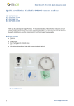
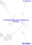
Package contents
•
•
•
•
•
Camera
Drill template
Set of wall plugs (ø 6 mm) and screws
Waterproof cap for RJ-45 connector
CD with recording software iVMS-4200, Camera Installation Wizard
Fig.1: Package contents
1
www.imago-video.com
IMAGO ITN-x2P3 NB 4 – Quick Installation Guide
Notice
•
•
•
•
•
•
•
•
•
•
•
•
•
•
•
•
•
The camera should be stored in a dry environment
Do not turn on the camera and do not work with voltage in a humid environment
Do not install cameras in a high humidity environment
Do not install your camera on unstable or vibrating surfaces or brackets
To remove the camera housing, use the included tools
Do not use excessive force during the installation – you might damage the device
If water gets into the camera, immediately disconnect it from the network and voltage supply
Do not touch the camera during a thunderstorm
Do not insert any objects in the camera
Do not perform any other mechanical modifications than those listed in this guide or user manual
Do not replace / adjust components on the printed circuit board and wiring of connectors
Do not use the camera with signs of damage or defects and/or with damaged cables
Do not repair your camera yourself; in case of failure, contact the supplier of your camera
Clean your camera with a cloth dampened with water - do not use chemicals, avoid abrasive materials when
cleaning
Connect the camera using the UTP or STP cable category 5 or higher, with the RJ-45 connector
The manufacturer is not liable for damages that were caused by unusual or unforeseeable circumstances and
the force majeure
Do not throw the camera in the trash; after the end of life of the equipment it is necessary to dispose of the
product according to your applicable local law. Use the collection points for WEEE in your area, ensuring the
environmentally friendly disposal or return the product to a vendor of electrical equipment
The physical installation of the camera
•
•
•
•
•
•
•
•
•
•
•
•
2
The camera can be mounted both on horizontal and vertical surfaces (wall, suspended ceiling, roof veneers etc.)
Select a location to install the camera, consider its location and direction to avoid the Sun in the view of the
camera
Cameras should be facing down to avoid direct Sun shining into the camera lens
The camera bracket has a cutout for cable outlet in case of a surface cabling – this cutout shall face directly down
Use a template to drill the mounting holes
o When installing the camera on a brick structure, drill the wall plug holes of ø 6 mm (indicated "1" in the
template) and insert the wall plugs into the holes
o For the cable entry drill holes with the diameter of at least 20 mm (indicated "A" in the template - not
needed if the cabling is guided on the surface, e.g. in a bar)
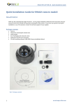
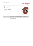
The camera is connected with the bracket with the ball joint – on the camera bracket release the matrix that
ensures the camera alignment - see Fig. 2 2
Use the supplied screws to attach the camera body, align it if necessary and tighten the nut on the bracket to
secure the position - see Fig. 2
No need to focus the camera as it has been focused by the manufacturer
Check the direction of the camera in a Web browser (see the next chapter) or adjust its direction
Connect the camera to a data switch using the UTP or STP cable with the RJ-45 connector - the camera is
powered via PoE - Power over Ethernet according to IEEE 802.3af standard; for power only use elements that
meet this international standard
If you do not have Power over Ethernet available, you can use the power adapter with the 12VDC/1A output (not
included)
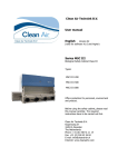
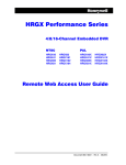
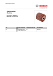
When routing the cable outdoors or in moist environments, use cap of the RJ-45 connector that ensures the
water resistance of the connection - see Fig. 3 and 4
www.imago-video.com
IMAGO ITN-x2P3 NB 4 – Quick Installation Guide
Fig. 2: Camera IDN31P1 NB 2.8 (nut to fix its
position)
Fig. 3 Dismantled cap of the RJ-45
connector
Fig. 4 Assembled cap of the RJ-45
connector
The first access to the camera
•
•
•
•
•
•
3
After connecting the camera to the power supply and the data network the camera can be accessed via a web
browser; the camera starts about 60 seconds.
The default setting of the camera:
o IP address:
192.0.0.64 (DHCP Client not enabled)
o User name:
admin
o Password:
12345
The camera can be found on the network using the application of the recording software iVMS-4200 on the
attached CD or can be downloaded at www.imago-video.com
Run the installation file from the CD (as a standard iVMS-4200.exe), accept the license agreement and follow the
instructions on the screen
After installation run the software iVMS-4200 Client and log in - default login data:
o User name:
admin
o Password:
choose your own password when loging-in for the first time
After logging in, use the "Settings" menu on the top bar and select the "Device Management"
www.imago-video.com
IMAGO ITN-x2P3 NB 4 – Quick Installation Guide
•
•
•
•
•
•
•
•
In the application a panel opens for configuring the devices managed by the recording software iVMS-4200
In the upper left part click on the tab "Server" and select "DVR, IPC, Encoder" from the list
In the bottom right part you will now see the available cameras on the network ("Online Device") - see Fig. 5
Double click on the found camera to open setting basic network parameters of the camera according to the
configuration of your network environment, enter the password for the user "admin" set in the camera, and save
by pressing the "Confirm" button
Open a Web browser and enter the IP address of the camera
Enter the login data and click on the "Login" button
After the first login you will be prompted to download and install the WebComponents addition that provides
the stream display in browsers.
Save the file (typically WebComponents.exe), close the web browser, run the downloaded installation file and
follow the on-screen instructions. After installation is complete, open the web browser again with the camera's
IP address and enter login information. Now you can view the live image from the camera.
Fig. 5: Software iVMS-4200 – searching for
camera in the network
Restoring the factory settings
•
•
•
•
•
Disconnect the camera from the power supply
Press and hold the "Reset" button which is located on the back of the camera body
Keep the button pressed and connect the camera to power supply
Hold the reset button for at least 10 seconds and then release it
After a while the camera will start with default parameters
We hope that you will be satisfied with the product. For general questions please contact your direct vendor.
www.imago-video.com
4
October 2014
www.imago-video.com