1
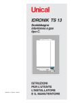
IDRONIK TS 13
Instantaneous gas
water heater, type C.
88
00333639 - 2 nd edition - 04/2011
ISTRUCTIONS FOR
INSTALLER, USER
AND SERVICE MAN
Warning: this manual contains instructions to be used exclusively by the
installer and/or a competent person in accordance with the current laws in
force.
The end user MUST not make any alterations to the water heater.
Failure to follow the instructions indicated in this manual, which is supplied
with the appliance, could cause injury to persons, animals or damage to
property. UNICAL shall not be held liable for any injury and/or damage.
CONTENTS
1
GENERAL INFORMATIONS ............................................................................................................................................................................. 3
1.1 Symbols used in this guide .......................................................................................................................................................................... 3
1.2 Correct use of the appliance ....................................................................................................................................................................... 3
1.3 Water treatment ............................................................................................................................................................................................ 3
1.4 Informations to be passed over to the user ............................................................................................................................................... 3
1.5 Safety warnings ............................................................................................................................................................................................ 4
1.6 Data badge .................................................................................................................................................................................................... 5
1.7 General warnings ......................................................................................................................................................................................... 6
2
TECHNICAL FEATURES AND DIMENSIONS ................................................................................................................................................. 7
2.1 Technical features ........................................................................................................................................................................................ 7
2.2 Dimensions ................................................................................................................................................................................................... 7
2.3 Main components ......................................................................................................................................................................................... 8
2.4 Operational data ........................................................................................................................................................................................... 8
2.5 General features ........................................................................................................................................................................................... 8
3
INSTRUCTIONS FOR THE INSTALLER .......................................................................................................................................................... 9
3.1 General warnings ........................................................................................................................................................................................ 9
3.2 Installation standards ................................................................................................................................................................................ 10
3.3 Packaging .................................................................................................................................................................................................. 10
3.4 Water heater location ................................................................................................................................................................................ 11
3.5 Mounting of the appliance ......................................................................................................................................................................... 12
3.6 Gas conne ction ........................................................................................................................................................................................ 13
3.7 Water connection ...................................................................................................................................................................................... 12
3.8 Ventilation requirements ............................................................................................................................................................................ 13
3.9 Smoke evacuation connection ................................................................................................................................................................. 13
3.10 Electrical connections ............................................................................................................................................................................... 15
General warnings ...................................................................................................................................................................................... 15
Connection to electrical supply 230V ...................................................................................................................................................... 15
3.11 Commissioning .......................................................................................................................................................................................... 15
4
USER’S INSTRUCTIONS ................................................................................................................................................................................. 18
4.1 Control panel .............................................................................................................................................................................................. 18
4.2 Useful suggestions and put in operation ................................................................................................................................................. 18
4.3 Ordinary maintenance .............................................................................................................................................................................. 18
5
INSPECTION AND SERVICE ........................................................................................................................................................................... 18
6
ERROR CODES ................................................................................................................................................................................................ 19
General information
1
GENERAL INFORMATION
1.1 - SYMBOLS USED IN THIS GUIDE
When reading this guide particular care has to be given to the parts marked with the following symbols:
DANGER!
Indicates serious danger for your
personal safety and for your life
WARNING!
Indicates a potentially dangerous
situation for the product and the
environment
NOTE!
Suggestions for the
user
1.2 - CORRECT USE OF THE APPLIANCE
The water heater IDRONIK has been designed utilizing today’s technology and in compliance with the
current safety regulations.However, following an improper use, dangers could arise for the safety and life
of the user or of other people, or damage could be caused to the appliance or other objects.The appliance
is designed for the domestic hot water production. Any other use of this appliance will be considered
improper.UNICAL declines any responsibility for any damages or injuries caused by an improper use; in
this case the risk is completely at the user’s responsibility.In order to use the appliance according to the
scopes it was designed for it is essential to carefully follow the instructions indicated in this guide.
1.3 - WATER TREATMENT
•
The hardness of the mains water supply conditions the frequency with which the heat exchanger is cleaned.
•
In hard water areas where the main water can exceed 15°f total hardness, a scale reducing device is
recommended. The choice of this device has to be made taking into consideration the characteristics of the
water.
•
In order to improve the resistance to lime scale it is recommended to adjust the domestic hot water temperature
as near as possible to the one you really require.
•
We recommend you to check the state of cleanliness of the heat exchanger at the end of the first year and
subsequently, on the basis of the lime scale found, this period can be extended to two years.
1.4 - INFORMATIONS TO BE HANDED OVER TO THE USER
The user has to be instructed on the use and operation of his D.H.W. system, in particular:
•
Hand over these instructions to the end user, together with any other literature regarding this appliance,
placed inside the envelope contained in the packaging. The user has to keep these documents in a safe
place in order to always have them at hand for future reference.
•
Inform the user on the importance of air openings and of the flue outlet system, stressing the fact that it is
absolutely forbidden to make any alterations to the appliance.
•
Inform the user how to adjust the correct water temperature in order to save energy.
•
Remind the user that, in compliance with the rules in force, a comprehensive control and service of the
appliancmust be performed in compliance with prescriptions and with the frequency indicated by the
manufacturer.
•
If the appliance is sold or transferred to another owner or if the present user moves home and leaves the
appliance installed, ensure yourself that the manual always follows the appliance so that it can be consulted
by the new owner and/or installer.
Failure to follow the instructions indicated in this guide, which is supplied with the appliance, could cause
injury to persons, animals or damage to property. The manufacturer shall not be held liable for any such
injury and/or damage.
3
General information
1.5 - SAFETY WARNINGS
Warning!
The appliance must not be used by persons with limited capacities, physical, mental and sensory.
These persons must be previously instructed and watched during the operations of transition.
WARNING!
The installation, adjustment, and servicing of this appliance must be carried out by a competent person
and installed in accordance with the current standards and regulations. Failure to correctly install this
appliance could cause injury to persons, animals or damage to property. The manufacturer shall not be
held liable for any injury and/or damage.
DANGER!
Servicing or repairs of the appliance must be carried out by UNICAL authorised service technicians; UNICAL
recommends drawing up a service contract. Bad or irregular servicing could compromise the safe operation of
the appliance, and could cause injury to persons, animals or damage to property for which UNICAL shall not be
held liable.
Modifications to parts connected to the appliance
Do not carry out any modifications to the following parts:
- the boiler
- to the gas, air, water supply pipes and electrical current
- to the flue pipe, safety relief valve and its drainage pipe
- to the constructive components which influence the appliance’s safe operation
WARNING!
When tightening or loosening the screw pipe connections, use only adequate fork spanners.
The improper use and/or the use of inadequate equipment can cause damages (for example water or gas
leakages).
WARNING!
Indications for appliances operating with propane gas
Ensure yourself that before installing the appliance the gas tank has been purged.
For a correct purging of the tank contact the liquid gas supplier or a competent person who has been legally
authorized.
If the tank has not been correctly purged problems could occur during ignition.
If this occurs contact the liquid gas tank’s supplier.
Smell of gas
If you smell gas follow these safety indications:
- Do not turn on or off electrical switches
- Do no smoke
- Do not use the telephone
- Close the main gas tap
- Open all windows and doors where the gas leakage has occurred
- Inform the gas society or a company specialized in installing and servicing heating systems
Explosive and easily inflammable substances
Do not use or leave explosive or easily inflammable material (as for example: petrol, paint, paper) in the room
where the appliance has been installed.
4
General information
1.6 - DATA BADGE
CE marking
The CE marking certifies that the appliance complies with:
- The essential safety requirements of the relevant gas appliances directive
2009/142/EC.
The label is positioned on the external part of
the frontal shell (to the left side).
®
1
2
3
4
5
6
A
7
8
10
9
B
12
11
13
C
14
KEY:
1 = CE surveillance Notified
Body
2 = Appliance model
3 = (S.N°) Serial Number
4 = Approved smoke
evacuation types
5 = P.I.N. Product Identification
Number
6 = (NOx) NOx class
A = Features of the D.H.W.
circuit
7 = (Pn) Nominal Output
8 = (Qmax) Nominal max. input
9 = (PW) Max. D.H.W. Working
Pressure
10 = (T max) Max. D.H.W.
Working Temperature
B
11
12
13
=
=
=
=
Electrical Data
Electrical supply
Electrical consumption
Protection degree
C = Factory settings
14 = Adjusted for gas type X
D
15
16
17
D = Destination countries
15 = Direct and indirect destination countries
16 = Gas category
17 = Feeding pressure
18 = Space for national marks
18
5
General information
1.7 - GENERAL WARNINGS
This instruction manual is an integral and indispensable
part of the product and must be retained by the user.
Please read carefully the instructions contained in this manual
as they provide important indications regarding the safe
installation, use and servicing of this appliance.
Keep this manual in a safe place for future reference.
The installation and servicing must be carried out in
accordance with the regulations in force according to the
manufacturer’s instr uctions and by legally competent
authorized persons.
The installations for the domestic hot water production
MUST be build, in their entirety, with materials (taps, pipes,
fittings, etc.) approved for drinkable water.
By a competent person, we imply a person who has a
specific technical qualification in the field of components
for central heating systems for domestic use, domestic
hot water production and servicing. The person must have
the qualifications foreseen by the current laws in force.
A wrong installation or a bad servicing could cause injury to
persons, animals or damage to property. The manufacturer
shall not be held liable for any such injury and/or damage.
Before carrying out any cleaning or servicing turn off the
electrical supply to the boiler by means of the ON/OFF switch
and/or by means of the appropriate shutdown devices.
Do not obstruct the intake/outlet terminal ducts.
6
In the event of failure and/or faulty functioning of the appliance,
switch off the appliance. Do not attempt to make any repairs:
contact qualified technicians.
Any repairs must be carried out by Unical authorized
technicians and using only original spare parts. Nonobservance of the above requirement may jeopardize the
safety of the appliance and cause the expiring of the
guarantee.
To guarantee the efficiency and correct functioning of the
appliance it is indispensable to have the appliance serviced
annually by a qualified person.
If the water heater remains unused for long periods, ensure
that any dangerous parts are rendered innocuous.
Before putting again into service an appliance which has been
unused for a certain time, proceed to rinse the domestic hot
water circuit, making the water flowing for the time necessary
to draw the full content of the domestic circuit.
If the appliance is sold or transferred to another owner or if the
present user moves home and leaves the appliance installed,
ensure yourself that the manual always follows the appliance
so that it can be consulted by the new owner and/or installer.
Only original accessories must be used for all appliances
supplied with optionals or kits (including electrical ones).
This appliance must be used only for the purposes for which
it has been expressively designed. Any other use shall be
considered incorrect and therefore dangerous.
Technical features and dimensions
2
TECHNICAL FEATURES
AND DIMENSIONS
2.1 - TECHNICAL FEATURES
The water heater IDRONIK TS 13 is an appliance operating
on gas, with a two section burner which distinguishes for its
extremely reduced depth: only 10 cm.
IDRONIK TS has an input of 22,5 kW;
This appliance is of category II2H3P.
The gas water heater IDRONIK TS is complete with all the
safety and control devices foreseen by the relevant Standards.
Furthermore it complies with:
- Gas Appliances Directive 2009/142/EC
- ElectroMagnetic Compatibility Directive 2004/108/EC
- Low Voltage Directive 2006/95/EC
COMPONENTS DESCRIPTION:
• Two section burner
• Ultraflat wet chamber heat exchanger
• Double opening gas valve;
• Electronic ignition;
• D.H.W. flow rate adjuster;
• Simple touch panel board
• Total safety system MPS
- Continuous self diagnosis
- safety lockout
- protections against:
- overheating
- fan failures
- overloads
- short circuits and over pressures
- freezing
• Coaxial air intake/smoke evacuation duct Ø60/100 mm
5
6
4
7
3
2
1
8
1
C
3
1
1
9
F
G
2
0
2.2 - DIMENSIONS
103
359
Coaxial duct for
air intake/smoke evacuation Ø100/60
567
Casing
Display
Panel board
C
Electrical supply
230 V - 50 Hz
G
F
D.H.W. Flow rate adjuster
Drain cock
7
Technical features and dimensions
2.3 - MAIN COMPONENTS
5
6
4
1
2
3
4
5
6
7
8
9
10
11
12
13
D.H.W. outlet1/2’’
Fan
Room sealed combustion chamber
Heat exchanger
Air intake/Smoke outlet
Limit thermostat
Electrical connection box
Gas valve
D.H.W. flow rate adjuster
D.C.W. inlet 1/2’’
Water heater drain cock
IGas inlet 1/2’’
Electrical supply cable
7
3
8
2
1
9
C
13
12
G
11
F
10
2.5 - GENERAL FEATURES
2.4 - OPERATIONAL DATA
IDRONIK TS 13
Nominal Input Qn
Minimum Input
Nominal Output Pn
Minimum Output
Efficiency at nominal load
Efficiency at partl load
Gas type
Category
Nominal gas feeding pressure
Burner nozzle N. Off
Burner nozzle Ø
Smoke evacuation type
kW
kW
kW
kW
%
%
mbar
mm
22,5
8,5
20,5
7,6
91
89
2H (G20) - 3P (G31)
II2H3P
20 (G20) - 37(*) (G31)
10
1,30 (G20) - 0,95 (G31)
C 13
(*) if the gas supply pressure exceeds 37 mbar it is necessary to
install a gas pressure regulator
8
D.H.W. drawing range
D.H.W. production with Δt 25 K
Minimum water pressure
Maximim water pressure
Minimum water temperature
Maximum water temperature
Electrical supply Tension/Frequency
Fuse on the electrical supply
Max. absorbed output
Protection degree
Dry weight
Water connection dia.
Gas connection dia.
Coaxial duct
Ignition method
l/min.
l/min.
bar
bar
°C
°C
V-Hz
A (F)
W
IP
kg
Ø
Ø
Ø mm
da 2,8 a 12,2
12,2
0,5
10
35
60
230/50
2
48
44
20
1/2’’
1/2’’
60/100
impulse
Instruction for the installer
3
INSTALLATION
ISTRUCTIONS
3.1 - GENERAL WARNINGS
WARNING!
This appliance has to be destined for the
use for which it has been expressly
designed.
Any other use shall be considered
improper and therefore dangerous.
This appliance is designed to heat water at
a temperature inferior to boiling point at an
atmospheric pressure.
Before installing the appliance the following
points have to be carried out by a competent
engineer:
a) The whole system should be thoroughly
flushed in order to remove any residual dirt
or grime which could compromise correct
water heater operation.
b) Check that the appliance has been preset
for operating with the gas type available.
This is verifiable via the indication on the
packaging and on the data badge;
c) Check that the chimney/flue pipe has an
adequate draught, does not have any
constrictions, and that no other appliance’s
flue outlets have been fitted, unless the
chimney is serving more than one heating
appliance, according to the specific
standards and regulations in force. The
connection between the boiler and
chimney/flue outlet can be made only after
this verification has been carried out.
WARNING!
The appliance must be installed only on a
vertical flat wall, made of non combustible
material.
The appliance must be positioned so that at
least the minimum operational and servicing
clearances are provided.
WARNING!
This manual has been edited following the prescriptions and definitions adopted by the European Standards.
WARNING!
In rooms where aggressive vapours or
dust are present the appliance must
operate independently from the air present
in theappliance’s location room!
WARNING!
The appliance must be installed by a
qualified engineer, who complies to the
technical professional rules in force and
whom, under his own responsibility,
guarantees the compliance of the
standards according to the latest
regulations.
9
Instruction for the installer
3.2 - STANDARD CODES FOR INSTALLATION
IDRONIK TS is of the gas category I2H.
The appliance must be installed in compliance to the
instructions contained in this manual.
The installation must be carried out by a competent qualified
engineer, whom will assume the esponsibility of complying
to all the local and/or national regulations published in the
official publications, as well as all the applicable codes of
practice.
The installation must be carried in accordance to the codes
of practice, the national and local regulations and the
requirements in force.
The appliance must be installed, commissioned and serviced
according to the regulations in force. This is also valid for the
hydraulic system, the flue outlet system and the location
room.
3.3 - PACKAGING
The IDRONIC TS water heater is supplied fully assembled
in a strong cardboard box.
After having unpacked the boiler check that it is
intact and undamaged.
DO NOT DISPERS IN THE ENVIRONMENT
Keep the packaging material (cardboard box,
plastic bags, polyester protection etc.) out of
the reach of children as they can be
dangerous.
UNICAL refuses all liability for injury to persons, animals or
damage to property deriving from not having respected the
above mentioned recommendations.
In the packaging, in addition to the water heater, you can
also find the following contents:
- This installation and servicing and user’s manual
- The Warranty card
- Nr. 2 spare parts request coupons
The coaxial duct Kit, Ø 60/100, for air intake and smoke evacuation, is packaged separate cardboard.
10
A = 430 mm
B = 755 mm
C = 230 mm
Instruction for the installer
3.5 - WATER HEATER INSTALLATION
3.4 - WATER HEATER LOCATION
When selecting the position for the installation of the boiler
please comply to the following safety requirements:
• Fit the appliance in rooms protected from frost;
• In rooms where aggressive vapours or dust are present,
the appliance must be able to operate independently from
the air of the location room;
• The appliance must be installed exclusively on a vertical
and solid wall, capable of adequately supporting the
weight of the water heater;
• The wall must not be made of flammable material;
• Leave on each side of the appliance a clearance of 50
mm, at least 200 mm on the upper side and 400 mm on the
lower side in order to allow easy service works.
WARNING
The water heater is for suitable for outdoor
installation.
Before connecting the water heater the following
requirements must be carried out by competent and qualified
engineers:
a) The system is flushed out with water in order to
eliminate any solid element which could reach the water
exchanger and affect the proper running of the water
heater;
b) Check that the appliance has been preset for operating
with the gas type available.
This is verifiable via the indication on the packaging and
on the data badge;
c) Check that the chimney/flue pipe has an adequate draught,
does not have any constrictions, and that no other
appliance’s flue outlets have been fitted, unless the chimney
is serving more than one heating appliance, according to
the specific standards and regulations in force. The
connection between the boiler and chimney/flue outlet can
be made only after this verification has been carried out.
For the fitting of the appliance:
- Determine the position of the fixing holes (upper position) of
adequate diameter and use the two expanding hooks as
shown
HOW TO FIT THE APPLIANCE TO THE WALL
180
- Hung the appliance and fix it using expanding screws ‘’B’’ in
the lower part.
- Mark the positions for gas and water connections.
130
20
‘’A’’
180
35
595
C
‘’D’’
G
C
F
D
95
G
45
F
Gas connection - ½''
D.H.W. Outlet connection - ½''
D.C.W. Inlet connection - ½''
Pressure relief valve drain pipe
In correspondence to the pressure relief valve
provision should be made to install a
discharge pipe with a funnel and a siphon
which lead to an adequate drainage. The
drainage has to be controllable by sight.
57 67 57
182
‘’B’’
WARNING!
If this precaution is not taken it could lead to injury to
persons, animals or damage to property.
The manufacturer shall not be held liable for any such
injury and/or damage.
11
Instruction for the installer
3.6 - GAS CONNECTION
DANGER!
The gas connection must be carried out
only by a qualified engineer who will have
to respect and comply to the regulations in
force and to the requirements indicated by
the local gas supplier. An incorrect
installation could cause injury to persons,
animals or damage to property. The
manufacturer shall not be held liable for
any injury and/or damage.
Before installing the boiler it is
recommended to thoroughly clean all the
fuel feed pipework in order to remove any
eventual residual grime which could
compromise the boilers correct
functioning.
If you smell gas:
a. Do not turn on or off electrical switches,
use the telephone or any other object
which can provoke sparks;
b. Open all doors and windows in order to
allow fresh air to enter and purify the room;
c. Close all gas cocks;
d. Contact a service engineer, qualified
installer or the gas supply company.
As a safety measure against gas leaks,
Unical recommends installing a surveillance
and protective system composed of a gas
leakage detector combined with an on-off
selenoid valve fitted on the gas supply line.
.
The gas supply pipe must have a section which is identical
or greater then the one used on the boiler and must assure
a correct gas pressure.
It is however important to comply with the National or Local
Installation Standards.
Before commissioning an internal gas distribution system
and therefore before connecting it to the gas meter, the
complete installation must be tested for gas soundness.
If any part of the system is concealed from view the gas
soundness test must be carried out before covering the
pipes.
Before connecting the pipework the system must be tested
with air or inert gas at a pressure of at least 100mbar.
Before commissioning the boiler ensure that the following
operations are carried out:
- Open the gas meter cock and vent the air contained in the
piping and subsequently proceed to vent device by device.
- Check, with the gas cock turned off, that there are no gas
leaks. During the 2nd quarter of the hour from the start of the
test, no pressure reduction should be detected by the
pressure gauge. Any gas leaks must be found by using only
water soap solutions, or an equivalent product, and
eliminated. Never look for gas leaks using a naked flame.
3.7 - WATER CONNECTIONS
WARNING!
Before connecting the water heater to the
water supply and distribution system we
recommend that the system is flushed out
with a product suitable for human use in
order to eliminate any metallic tooling or
brazing residues, oil and grime which could
reach the exchanger and affect the proper
running of the water heater.
Non-observance of these instructions
could cause injury to persons, animals or
damage to property. The manufacturer
shall not be held liable for any such injury
and/or damage.
The hot water distribution pipe and the cold water supply pipe
have to be connected to the relevant 1/2” connections C and
F as shown on page 11.
It is suggested to fit a gate valve at the inlet of cold water.
12
The water supply pressure has to be within 1
and 4 bar. In case of pressure higher than 5 bar
we suggest to fit a pressure reducing valve.
WARNING!
The hardness of the feeding water conditions
the descaling frequency of D.H.W. heat
exchanger.
Depending on the hardness of the feeding water it must be taken into consideration the installation possibility of dosing devices of products for human use for the treatment of the
domestic water.
When the water hardness is higher than 15°f
the water treatment is always suggested.
Ascertain that the water pipes are not used as
earthing of the electrical or thelephon installations. They are not absolutely suitable for this
use. In a short time this could cause serious
damage to the piping and to the water heater.
Instruction for the installer
3.8 - ROOM VENTILATION
The appliance has to be installed in a convenient room in
conformity with the rules inforce, and particularly:
because the IDRONIK TS is of C13 type in terms of smoke
evacuation (the combustion circuit is separate from the air of
the room in which the water heater is installed), there are no
particular recommendations concerning the ventilation openings for the combustion air.
3.9 - SMOKE EVACUATION CONNECTION
We recommend using only original UNICAL
flue outlet systems.
Damages caused by installation errors and
for non-observance of the instructions given
by the same manufacturer will invalidate all
the supplier’s contractual or extra
contractual responsibilities.
SMOKE EVACUATION WITH COAXIAL DUCT
Ø 60/100 mm
Type C13
The minimum allowed length of the coaxial duct is 0.5 m.
The maximum allowed length of the coaxial duct is 3 m; for
each added curve the maximum allowed legth will be reduced by 1 m.
The curves N. off will be in any case less than 3.
When replacing an existing water heater ALWAYS replace
also the coaxial duct.
B
The appliance is CE certified for the smoke evacuation type:
C13 Appliance conceived for connection to coaxial horizontal duct for air intake and smoke evacuation directly from
and to the outside.
A
13
Instruction for the installer
Important:
The coaxial duct must have a sloope toward
the outside of 2%, in order to allow to the
outside the possible condensate.
pendenza
2%
Example 1: LATERAL AIR INTAKE/SMOKE EVACUATION
2°
2°
<
20
<
Example 2: REAR AIR INTAKE/SMOKE EVACUATION
Minimo 500
2°
<
14
20
00262980
Coaxial kit Ø 60/100, supplied as
standard, made of:
(coaxial curve + coaxial terminal
Ø 60/100 + adapter)
00262981
Coaxial extension (option)
Ø 60/100
20
Instruction for the installer
3.10 - ELECTRICAL CONNECTIONS
DANGER!
- Before removing the casing front panel
switch off the electrical supply.
General warnings!
The appliance’s electrical safety is guaranteed only when
the same appliance has been correctly earthed in
compliance with the regulations in force. The gas and water
feeding pipes cannot be used as ground plates.
Ensure that the above safety electrical requirements subsist;
in case of doubt, ask for a professionally qualified
technician to check the appliance’s electrical system.
UNICAL refuses responsibility for any damages arising from
failure to earth the boiler correctly.
It is necessary that a qualified technician verifies that the
electrical system is adequate to the appliance’s maximum
absorbed power, indicated on the data plate, verifying in
particular that the section of the system’s cables is suitable
to the appliance’s maximum absorbed power.
For the appliance’s general electrical supply the use of
adaptors, multiple sockets and/or extension cords is strictly
forbidden.
The use of any power supplied equipment implies the
observance of several fundamental rules, such as:
- Do not touch the appliance with any wet part of your body
and/or barefooted;
- Do not pull the supply cables;
- Do not expose the boiler to sunlight, rain, etc., unless it is
explicitly foreseen;
- Do not permit children or inexpert people to use the
appliance.
Connection to mains supply 230V
(Installation of a double pole switch)
3.11 - INITIAL LIGHTING
Preliminary checks
Before the initial lighting of the water heater it is suggested to
check:
-
Informations to be passed on to the user
The user must be instructed on the use and operation of
his water heater and in particular:
•
- Hand over to the end user this manual, as well as all the
other literature relative to the appliance and placed in the
envelope contained in the packaging.
The user must retain this literature for any future
reference.
•
Remind the user that in order to comply to the
regulations in force the water heater has to be inspected
and serviced regularly as indicated by the manufacturer.
•
Explain and demonstrate to the user the correct temperature adjustment for the economic use of the appliance.
•
Remember, that in compliance with regulation, control and
maintenance must be performed in accordance with the
requirements and the frequency specified by the manufacturer and with the frequency required by the directives
of the law.
•
If the appliance is sold or transferred to another owner or
if the present user moves home and leaves the appliance
installed, ensure yourself that the manual always follows
the appliance so that it can be consulted by the new
owner and/or installer.
The boiler is provided complete with a 1,5 m long, mains
supply cable, with a cross section area of 3x0,75 mm2.
A mains supply of 230 V – 50 Hz is required. The wiring to
the boiler must be in accordance with the current IEC
regulations.
DANGER!
The electrical connections must be carried
out only by a qualified engineer.
Before carrying out the connections or any
other operation on the electrical parts,
always switch off and disconnect the
electricity supply and ensure yourself that
it cannot be accidentally turned on.
Note: It is necessary to fit a double pole switch on the
electrical supply line, having a 3 mm contact separation in
both poles, in an easy accessible position so as to ensure
quick and safe servicing.
the installation is in conformity with the relevant applicable standards;
the coaxial duct for the air intake and smoke evacuation is
properly fitted;
gas feeding pipe properly sized for the flow rate necessary to the appliance;
the electrical supply is 230V - 50Hz;
the feeding gas cock is turned on;
the soundness of the gas supply;
the external main switch is turned on; '
the outlet of the safety valve “D” is connected to the swage.
there are no water leaks;
the ventilation conditions and the minimum clearances,
for the completion of the service operation, when the appliance is fitted in between the cabinets or in a capboard,
are guaranteed.
The replacement of the supply cable as to be carried out by
a qualified authorized UNICAL engineer, using only original
spare parts. The non-observance of the above could
compromise the appliance’s safety.
15
User’s operating instructions
4
ISTRUCTIONS FOR THE USER
4.1 - PANEL BOARD
H
E
F
G
88
A
B
D
C
A =
B =
C =
D =
Ignition button
Temperature setting push buttons
(+ increases and - reduces)
D.H.W. flow rate adjuster
Drain valve
4.2 - USEFUL SUGGESTIONS AND
PUT IN OPERATION
Dare tensione all‘apparecchio
Aprire i rubinetti di intercettazioni acqua
Open the gas cock
Push the ignition button ‘‘A‘‘: on the display it is shown the
set up procedure with the ‘‘G‘‘ illuminated.
Push the adjusting temperature button ‘‘B‘‘ to set the desired
drawing temperature.
The minimum settable temperature is 35°C; the
maximum settable temperature is 60°C,
adjustable 1 by 1°C. Normally the outlet
temperature of hot water is for a shower of about
40°C.
16
E
F
G
H
=
=
=
=
Burner in operation
Temperature value / Error code
Hot water available
Fan in operation
Adjust the hot water flow rate ‘‘C‘‘ up to the necessary water
flow rate is obtained.
Open a hot water tap: on the display it is shown the hot water
icone ‘‘G‘‘ , togheter wit the symboles ‘‘E‘‘ and ‘‘H‘‘ (they indicate
that the water is getting warm to the temperature shown on
the disply).
If the water heater has some problem, on the
display you will get the correspondent error
code in position ‘‘F‘‘.
- close the water tap and then re-open it
- switch on and off the appliance through the On and Off
switch ‘‘A‘‘; if the water heater continues in getting problems,
close the gas cock and turn off the power supply.
- after some time restart it.
User’s operating instructions
Adjust the water flow rate through the knob
‘‘C‘‘and the hot water temperature through the
button ‘‘B‘‘, according to your own needs. It is
good to get familiar with the appliance commands
by repeating several times the ignition procedure
after the installation or the first use.
When the water tap is open while the ignition
button if off, the water heater doesn‘t work: only
cold water runs through it. If hot water is needed,
you have just to push the button ‘‘A‘‘.
When the water tap is closed, the water heater is
switched off, but the fan continues working still
for a few seconds.
A too low or too high water presure can cause
an anomalous combustion.
In these cases don’t use the water heater up to
when the water pressure returns to the normal
value.
The dust, in time, could cause the lockout of
the water heater and compromise the combustion with increase of the carbon monoxide. It is
then necessary to call a qualified technician
for cleaning and remove the dust and soot
every six months in order to make sure the
combustion products are evacuated regularly.
The water heater must be installed vertically.
The outlet water temperature doesn‘t
correspond exactly to the pre-set temperature.
Freezing prevention
In case of extended periods of operation below
zero, it is suggested:
Safety precautions
1 - Close the cold water tap.
Gas accidents prevention
Make sure the flame extinguishes after the use.
2 - Turn the water flow rate adjusting knob to its
“MAX” position.
Check the soundness of the gas connections
with a soap solution. If a gas leack should be
detected open immediately the windows and
don‘t switch on or use electrical appliances, or
connect or disconnect plugs from sockets,
because flames or sparks can provoque
explosions.
3 - Turn the drainage valve ‘‘D‘‘ and extract it,
re-position it when the residual water has been
completely drained.
Fire Prevention
In case of lack of ignition or lack of D.H.W.
drawing close the gas and water taps.
Don’t place onto the water heater towels or
clothing.
Don’t store flammable substances in the proximity of the water heater.
Prevention from carbon monoxide poisoning
This water heater takes the air for combustion
and discharges the combustion products through the coaxial duct, that, for this reason, has to
be installed as specified in the paragrapf 3.9. A
wrong installation could create dangers up to
the death.
PRECAUTIONS
- If you open the water tap before switching on
the water heater, this will not start automatically.
- When taking a shower, in order to avoid being
scalded, make sure the water temperature is
at an acceptable value.
- After using water at high temperature, in order
to avoid the risk of being scalded at the next
use, adjust the water temperature at an
acceptable value.
Behaviour in anomalous conditions
In case of noisy combustion, smoke at the outlet or poor combustion, close the gas gate valve, switch off the appliance and contact the
service center.
Prevention of scald injury (if the casing is
removed)
The qualified technician , after removing the
casing, must check the flame via the sight
glass.
During this operation it is important to take care
and stay at a minimum distance of 300mm.
17
User’s operating instructions
4.3 - ORDINARY MAINTENANCE
Maintenance
- Clean monthly the water inlet filter.
- Always make sure there are no water leaks.
- Ask a professionally qualified technician for an inspection
to the burner, the evacuation system and the fan every six
months.
- Inspect always the flame inside the water heater for detecting possible anomalous conditions.
- The gas valve is operated by the water pressure; if the
water pressure is below 0.5 bar the water heater cannot
work.
- The safety valve drips when the water pressure is too
high: it will release somme drops in order to reduce the
pressure and protect the water heater.
- When more water drawings are contemporaneous (2 or 3
taps open at the same time) the flow rate of each tap can be
reduced or the temperature can decrease.
- The formation of white plumes, with low outer temperature,
is normal (white smoke).
- When the outlet water temperature is too high:
- Reduce the temperature by acting on the knob ‘’B’’ (TEMP
- MINUS); if this is not enough increase the flow rate by
acting on the adjuster ’’C’’ (MAX).
- When the outlet water temperature is too low:
- Increase the temperature by acting on the knob ‘’B’’ (TEMP
- PLUS); if this is not enough reduce the water flow rate
by acting on the adjuster ’’C’’ (MIN).
- Once the hot water drawing is finished, the fan will continue operating for some time and the will go off automatically.
- Select the most convenient type of shower head (multifunc tion) in order to obtain the best results in terms of
temperature and quantity of water.
18
5
INSPECTION AND
MAINTENANCE
Inspection and services, correctly made and
at regular intervals, as well as the use of original spare part, are very important for a
proper, trouble free operation and for the long
lasting of the appliance.
If inspections and maintenance are not regularly performed it can result in material
and personal injuries, for which the manufacturer cannot be considered responsible.
For this reason we recommend to stipulate a service contract
with an authorised Unical Service Center.
The inspection helps in determining the actual state of an
appliance and in comparying it with the optimal state. This
happens through measurements, controls and observation.
For a better operation of your appliance in the section 4.3 the
suggested maintenance operations are suggested.
Instructions for inspection and maintenance
In order to assure for long time the correct operation of
your appliance without altering the working conditions of
your standard product, only original Unical spare parts
have to be used.
Before proceeding with the maintenance operations, follow
strictly the following operations:
• Switch off the electrical supply to the appliance.
• Separate the appliance from the mains through a cutting
device having, at least, 3 mm distance between the contacts and make sure the electrical supply cannot be
switched on by mistake.
• Close the gas gate valve upstream the appliance.
• If necessary, and depending on the intervention to be done,
close the cold water inlet tap.
• Remove the front casin of the appliance.
Once all the service works have been done, perform always
the following operations:
• Open the cold water inlet cock (if previously closed).
• Open the gas gate valve.
• Switch on the electrical supply to the appliance and turn
on the external switch.
• Ascertainn the gas and water soundness of the piping.
• Refit the casing front panel.
Codes fault
6
ERROR CODES
The appliance has integral diagnosis system that, in case of
bad operation, allows the immediate indication of the fault
type on the panel board.
Herewith are listed the known error codes.
Fault thermostat
Actions: Contact the Service Center
Effect: Flame lockout
CODE
APPEARING
ON THE DISPLAY
Lack of ignition /
lack of gas supply
Actions: Open the gas cock
Effect: Flame lockout
CODE
APPEARING
ON THE DISPLAY
Obstructed discharging system /
excessive external ventilation
Actions: Contact Service Center
Effect: Flame lockout
CODE
APPEARING
ON THE DISPLAY
Faulty fan or its circuit
Actions Contact Service Center
Effect Flame lockout
CODE
APPEARING
ON THE DISPLAY
e0
E1
E3
LOCKOUT:
The resetting is done by cutting the power, or by closing and
opening the hot water tap.
STOP:
is intended ignition not allowed (SERVICE)
Maximum temperature ptotection
Actions: Control the circulation
Effect: STOP
CODE
APPEARING
ON THE DISPLAY
Faulty temperature sensor on the hot
water outlet
Actions: Cheks sensor and its connections
Effect: STOP
CODE
APPEARING
ON THE DISPLAY
Faulty gas valve
Actions: Check gas valve and its connections
Effect: STOP
CODE
APPEARING
ON THE DISPLAY
E5
E6
E8
E4
Table - PROBLEM LIST
19
AG S.P.A.
46033 casteldario - mantova - italia - tel. 0376/57001 (r.a.) - fax 0376/660556
www.unical.ag - [email protected]
The Unical declines every responsibility for the possible inaccuracies if owed to errors of transcript or press. Also
reserves the right to bring those changes that it will hold necessary to it own products or profits, without jeopardizing its
essential characteristics.