1
Town of Mono Monora Park Pavilion Building Expansion Project Prepared for 347209 Mono Centre Road Mono, ON June 17th, 2013 Prepared by S. Burnett & Associates Limited 210 Broadway, Unit 203 Orangeville, ON L9W 5G4 The material in this Contract reflects the best judgement in light of the information available at the time of preparation. S. Burnett & Associates accepts no responsibility for damages, if any, suffered by any third party as a result of decisions made or actions based on this document. S. Burnett & Associates Limited Town of Mono Municipal Council Monora Park Pavilion Building Expansion Project Addenda Addenda Town of Mono Municipal Council Monora Park Pavilion Building Expansion Project Contract No. MA12043 Index to Contract Documents Section Contents A Tender Ad B Tendering Information C Specifications D Articles of Agreement E Contractor Information S. Burnett & Associates Limited Section B Town of Mono Monora Park Pavilion Building Expansion Project Section A Tender Ad Tendering Information S. Burnett & Associates Limited Section A Town of Mono Municipal Council Monora Park Pavilion Building Expansion Project Tender Ad Town of Mono Municipal Council Monora Park Pavilion Building Expansion Project Contract No. MA12043 SEALED TENDERS, on forms supplied by the Consulting Engineer, will be received at the office of the Town of Mono at 347209 Mono Centre Road, Mono, ON until: Tuesday July 16th, 2013 at 11am “Eastern Standard Time” for the Monora Park Pavilion Expansion Project. Hard Copy submissions must be received before the 11:00am deadline in order to be considered. The tender includes the supply and all labour, materials and equipment necessary to: Facilitate the renovation of the building to meet accessibility requirements as per the design drawings and the tender specifications Installation of an elevator with associated mechanical room and connections Construction of the new layout as per the design drawings and the tender specifications with appropriate demolition Provide full accessibility in accordance with Ontario’s accessibility standards to the expansion Coordinate with electrical and mechanical contractors and provide plumbing services to the expansion and integrate with the original building were required. Specifications and the drawings are available from the Consulting Engineer listed below. Interested bidders shall note that a non-mandatory site visit is scheduled for Thursday June 27th, 2013 commencing at 10:00 am at the project site located at 500 Monora Park Road, Mono, Ontario. Written queries regarding this Tender are to be directed to Marissa Mallais by email [email protected] or David Dagenais by email [email protected]. Each tender must be accompanied by a certified cheque or bid bond to be retained by the Consulting Engineer for an amount of at least $5,000 made payable to the Town of Mono. This Contract is subject to receipt of approval of the Town of Mono. The lowest or any tender will not necessarily be accepted. Consulting Engineer S. Burnett & Associates Limited 210 Broadway, Unit 203 Orangeville, ON L9W 5G4 T: 519-941-2949 F: 519-941-2036 Owner Town of Mono 347209 Mono Centre Road Mono, ON L9W 6S3 T: 519-941-3599 F: 519-941-9490 S. Burnett & Associates Limited Section B Town of Mono Monora Park Pavilion Building Expansion Project Section B Tendering Information Tendering Information S. Burnett & Associates Limited Town of Mono Municipal Council Monora Park Pavilion Building Expansion Project Section B Tendering Information Table of Contents to Section B 1 GENERAL INFORMATION TO TENDERERS ................................................................................................4 1.1 Location and Scope of Work .....................................................................................................................4 1.2 Contract Approval ......................................................................................................................................4 1.3 Delivering and Closing of Tender .............................................................................................................4 1.4 Tender Submission ....................................................................................................................................4 1.5 Disqualification, Withdrawal and Qualifying Tenders .............................................................................4 1.6 Informal or Unbalanced Tenders...............................................................................................................5 1.7 Discrepancies In and Interpretation of Tender Documents ....................................................................5 1.8 Acceptance or Rejection of Tenders ........................................................................................................5 1.9 Tender Deposit and Bonding Requirements............................................................................................6 1.10 Formation of Contract ................................................................................................................................6 1.11 Subcontractors ...........................................................................................................................................7 1.12 Proof of Ability ............................................................................................................................................7 1.13 Construction Layout ..................................................................................................................................7 1.14 Construction Period, Working Days and Liquidated Damages ..............................................................7 1.14.1 Working Time Allotment ............................................................................................................................7 1.14.2 Working Day Extension ...................................................................................................................8 1.14.3 Liquidated Damages........................................................................................................................8 1.15 Preliminary Acceptance, Guaranteed Maintenance Period, Final Acceptance and Release of Holdback ..................................................................................................................................................................8 1.15.1 General............................................................................................................................................8 1.15.2 Procedure for Preliminary Acceptance ............................................................................................9 1.15.3 Release of Holdback .......................................................................................................................9 1.15.4 Period of Guaranteed Maintenance ...............................................................................................10 1.15.5 Procedure for Final Acceptance ....................................................................................................10 1.15.6 Release and Final Documentation ................................................................................................10 1.16 Sales Tax ...................................................................................................................................................10 1.17 Traffic and Pedestrian Control ................................................................................................................11 1.18 Co-operation with Other Contractors .....................................................................................................11 1.19 Local Specifications .................................................................................................................................11 1.20 Dispute Resolution ...................................................................................................................................11 S. Burnett & Associates Limited Town of Mono Municipal Council Monora Park Pavilion Building Expansion Project Section B Tendering Information 1.21 Existing Services ......................................................................................................................................12 1.22 General Instructions.................................................................................................................................12 1.23 Equivalents or Approved Equals ............................................................................................................13 1.24 Occupational Health & Safety Act ...........................................................................................................13 1.25 Amendments to OPS General Conditions of Contract ..........................................................................14 1.26 Fairness Is A Two Way Street Act (Construction Labour Mobility) 1999.............................................14 2 Tender Form ..................................................................................................................................................15 2.1 Tender Agreement ....................................................................................................................................15 2.2 List of Proposed Subcontractors ............................................................................................................18 2.3 Tenderer’s Experience in Similar Completed Work...............................................................................18 2.4 Contract Drawings....................................................................................................................................18 2.5 Schedule of Unit Prices ...........................................................................................................................19 2.6 Bid Bond and Agreement Bond ..............................................................................................................30 S. Burnett & Associates Limited Town of Mono Municipal Council Monora Park Pavilion Building Expansion Project 1 GENERAL INFORMATION TO TENDERERS 1.1 Location and Scope of Work Section B Tendering Information The Work included in this Contract is for the expansion of the Town of Mono Monora Park Pavilion Building located at 500 Monora Park Road, Mono, ON, L9W 2Y8. . The proposed work shall include the supply of all labour, materials and equipment as necessary for the construction of the works indicated on the drawings and described herein. All work is to be completed in accordance with the Contract Documents, Drawings, the Ontario Building Code, and local building requirements. 1.2 Contract Approval This Contract is subject to the approval of the Town of Mono. 1.3 Delivering and Closing of Tender Tenders consisting of the unbound copy of the Tender Form sealed in the envelope, which will be received at the office of the Town of Mono located at 347209 Mono Centre Road, Mono, Ontario Hard Copy Submission Until: Tuesday, July 16th, 2013 at 11:00 am “Eastern Standard Time” The Tender Form must be fully legible, signed and witnessed in the spaces provided, with the signature of the Bidder or a responsible official of the organization bidding. Contractors are encouraged to attend a nonmandatory site visit scheduled for Thursday, June 27th, 2013 at 10:00 am “Eastern Standard Time” to review the site conditions. 1.4 Tender Submission The unbound copy of the Tender Form provided with the tender package shall be submitted in its entirety. All sections of the Tender Form shall be completed. 1.5 Disqualification, Withdrawal and Qualifying Tenders Under no circumstances will tenders be considered which: a. Are received by the Owner or his authorized representatives after the closing time on the closing date specified herein. b. Are not accompanied by the Tender Deposit as specified. c. Are not accompanied with an agreement to bond. A Tenderer who has already submitted a tender may submit a further tender at any time up to the official closing time. The last tender received shall supersede all tenders previously submitted by that Tenderer for this Contract. Facsimile transmissions will not be accepted. A Tenderer may withdraw or qualify his tender at any time up to the official closing time by submitting a letter bearing his signature and seal as his tender to the point of tender delivery where the time and date of receipt will be recorded and the letter placed with the other tenders. Facsimile transmissions will not be accepted. S. Burnett & Associates Limited Town of Mono Municipal Council Monora Park Pavilion Building Expansion Project Section B Tendering Information Tender packages must be obtained from the Consulting Engineer, and Tenderers must be registered with said office in order to submit a bid. Tenderers not meeting these criteria are, at the discretion of the Owner, subject to disqualification. An electronic package of drawings and tender will be provided at no cost. Hard copy package shall require a non-refundable payment of $75 + HST payable to the consultant. 1.6 Informal or Unbalanced Tenders Tenders which are incomplete, conditional, illegible or obscure, or that contain additions, reservations, erasures, qualifications, alterations or irregularities of any kind may, but will not necessarily, result in the Owner’s rejection of the bid. Tenders that contain prices which appear to be as unbalanced as likely to adversely affect the interests of the Owner may be rejected. Tenders that are based upon an unreasonable period of time for the completion of the works may be rejected. Wherever in a tender the amount tendered for an item does not agree with the extension of the estimated quantity and the tendered unit price, the unit price shall govern and the amount and the Total Tender Price shall be corrected accordingly. The Owner reserves the right to waive formalities at his discretion. Tenderers who have submitted tenders that have been rejected by the Engineer and/or Owner because of informalities will be notified of the reasons for the rejection within ten (10) days after the tender closing date. 1.7 Discrepancies In and Interpretation of Tender Documents Should a Tenderer find discrepancies in, or omission from, the drawings, specifications, or other tender documents, or should he be in doubt as to their meaning, he should notify the Engineer who may send a written instruction to all Tenderers. No oral interpretation shall be made to a Tenderer as to the meaning of any of the tender documents, or be effective to modify any of the provisions of the tender documents. Addenda shall be issued by the Engineer to items in the tender as he determines. Addenda shall be in writing unless time prohibits mail delivery prior to tender closing. Facsimile transmissions may be used by the Engineer to issue addenda. 1.8 Acceptance or Rejection of Tenders Tenders will be evaluated to ensure that the Contractor has the appropriate qualifications and experience to complete this project. This evaluation will be based upon: Qualifications and related experiences of the Tenderer, senior personnel and subcontractors to be assigned to this project; Amount of work to be completed by Tenderers own forces versus subcontractors; S. Burnett & Associates Limited Town of Mono Municipal Council Monora Park Pavilion Building Expansion Project Section B Tendering Information Performance of the Tenderer and subcontractors on past projects, including, without limitation, the Tenderer’s history with respect to quality of work, scheduling, changes in the work, claims, disputes, level of satisfaction of Owners and Consultants, etc.; Conformance with the requirements set forth in the tender document; and Other such considerations as may be determined by the Owner to be in its own best interest. The Engineer and the Owner reserve the right to reject any tender from a contractor not meeting these qualifications. The Engineer and the Owner reserve the right to reject any or all tenders and to waive formalities, as the interests of the Owner may require, without stating reasons thereto. The bidder acknowledges that it shall have no claim against, or entitlement to damages from the Owner or the Engineer by reason of the Owner’s rejection of its bid or of all bids, or by reason of any delay in the acceptance of a tender. Tenders are subject to a formal Contract being prepared and executed. 1.9 Tender Deposit and Bonding Requirements Each tender shall be accompanied by either: a. A tender deposit in the form of a certified cheque made payable to the Owner for an amount equal to at least $5,000; or b. A Bid Bond of at least $5,000 and sealed by a corporation duly authorized to transact the business of Surety ship. The Tenderer shall include with his tender an Agreement to Bond as per the format of the specimen enclosed in Section B, executed under its corporate seal by the surety company from which he proposes to obtain the required bonds. Only bonds issued by insurers licensed in Ontario will be accepted as per the terms and conditions of the tender documents. Prior to execution of a Contract with the Owner, the Contractor will be required to furnish to the Owner a performance bond in the amount of 100 percent of the total tender price and a separate payment bond in the amount of 100 percent of the total tender price. The full cost of these bonds is deemed to be included in the total tender price for the project. In lieu of bonding, contractors may elect to provide either a letter of credit or security in the form of a certified cheque for an amount equal to at least 50% of the total tendered price. The tender deposit cheque of two Tenderers, as selected by the Owner, will be retained for 60 days or until such time as a Contract has been executed by the Owner and the successful Tenderer. 1.10 Formation of Contract The Engineer, when so instructed by the Owner, shall forward three complete copies of the Contract Documents to the successful Tenderer for execution. S. Burnett & Associates Limited Town of Mono Municipal Council Monora Park Pavilion Building Expansion Project Section B Tendering Information The Tenderer agrees that if he has been notified that his tender has been recommended to the Owner for acceptance he will fully execute the Articles of Agreement bound in the Contract Documents within ten (10) days after receiving those same Documents in triplicate. The successful Tenderer shall execute and return with the three (3) copies of the Contract Documents, to the Engineer within ten (10) days, the following in triplicate: a. Performance and Payment Bonds or security deposit in the form of a letter of credit or certified cheque; b. Current Clearance Certificate from the Workplace Safety & Insurance Board; c. Liability and All Risk Insurance Certificate as outlined in the General Conditions of Contract; and d. A Work Schedule outlining the proposed timing of the works. 1.11 Subcontractors The Tenderers shall list, on the page provided in Section 2.2, the name and address of each Subcontractor used in preparing his tender, stating that portion of the work allotted to each. Only one Subcontractor shall be named for each part of the work to be sublet. After a formal Contract has been executed, the Contractor shall not be permitted to substitute other Subcontractors in place of those named in his tender without the approval of the Engineer. 1.12 Proof of Ability The Tenderer shall, on the form provided in Section 2.3, provide proof of his experience and responsibility in successfully completing projects of a similar nature. This proof of ability shall apply in general to the Tenderer`s experience in similar work. The Tenderer’s senior supervisory staff and the experience of each, the Tenderer`s construction plan, and the name and business address of each proposed Subcontractor will also be provided if so requested within three (3) days of such a request being made by the Engineer. 1.13 Construction Layout The Contractor is responsible for the layout of all construction works. The Engineer may provide construction control points and benchmarks at the onset of the work. Replacement of the control points removed by the Contractor, subcontractor or suppliers shall be at the Contractor’s expense. 1.14 Construction Period, Working Days and Liquidated Damages 1.14.1 Working Time Allotment The Contractor shall complete all works to the point of substantial completion described herein and on the Contract drawings within twenty-two (22) weeks of Contract award. All construction activities to be completed prior to January 31st, 2014. The contractor shall note that weddings and events will be held at the facility most weekends throughout the project. Contractors will therefore be responsible for keeping the job site neat and tidy and maintain a temporary seal between the existing and facility at all times prior to final connection. The contractor will also S. Burnett & Associates Limited Town of Mono Municipal Council Monora Park Pavilion Building Expansion Project Section B Tendering Information be responsible for ensuring appropriate vehicle and pedestrian traffic and access to the existing facility at all times. A facility booking schedule will be provided to the successful contractor by the Mono Recreational Department. Under no circumstances will Friday evening, Saturday or Sunday construction be permitted. The contractor must ensure that the site is cleaned and presentable by 4:00pm on Friday for weekend bookings. Contractors shall be prepared to commence project preparation activities such as ordering, preparing shop drawings, preparing schedule and mobilization workforce within 10 days of notice of award. 1.14.2 Working Day Extension If the Contractor is delayed in the completion of the work for causes beyond the reasonable control of the Contractor, as determined by the Engineer, the time of completion shall be extended in writing at any time on such terms and for such period as shall be determined by the Engineer in accordance with OPS General Conditions of Contract. This may include an extended delivery of the specified elevator as determined at the sole discretion of the engineer. Under those circumstances contractors will be required to have completed all other aspects of the project including the elevator shaft and mechanical room to the specifications of the elevator supplier/installer included a written signoff of acceptance from the supplier/installer. 1.14.3 Liquidated Damages It is agreed by the parties to the Contract that in case all the work called for under the Contract is not finished or completed as set forth herein, damage will be sustained by the Owner and that it is and will be impracticable and extremely difficult to ascertain and determine the actual damage which the Owner will sustain by reason of such delay and the parties hereto agree that the Contractor will pay to the Owner the sum of Five Hundred Dollars ($500.00) for the liquidated damages for each and every calendar day delay in finishing the work in excess of the number of working days prescribed or the completion date specified and it is agreed that this amount is an estimate of the actual damage. The Owner may deduct any amount due under this paragraph from any monies that may be due or payable to the Contractor on any account whatsoever. The liquidated damages payable under this paragraph are in addition to and without prejudice to any other remedy, action or other alternative that may be available to the Owner. 1.15 Preliminary Acceptance, Guaranteed Maintenance Period, Final Acceptance and Release of Holdback 1.15.1 General For the purposes of this contract, Preliminary Acceptance and Substantial Completion will be assumed to have the same meaning except as distinguished in 1.15.2. It is intended that the Contractor guarantee to the Owner under normal operating conditions the work included in this Contract for a period of time as further described in Section 1.15.4; however, under no circumstances shall the Guaranteed Maintenance Period be less that twelve (12) months from the date of Preliminary Acceptance. Preliminary Acceptance is defined as the date that all services, as required by the Engineer, have been tested, cleaned, inspected and approved by the Owner’s Engineer and the Town of Mono. For the purpose of this Contract, Preliminary Acceptance shall not be granted prior to: 1. The work or a substantial part thereof is ready for use or is being used for the purpose intended; and S. Burnett & Associates Limited Town of Mono Municipal Council Monora Park Pavilion Building Expansion Project Section B Tendering Information 2. When the work remaining to be done under the Contract is capable of completion or correction at a cost of not more than: i. ii. 2 percent of the first $500,000 of the Contract price; and 1 percent of the balance of the Contract price. For the purpose of this Contract where the work or a substantial part thereof is ready for use or is being used for the purpose intended and/or where the work cannot be completed expeditiously for reasons beyond the control of the Contractor, the value of the work to be completed shall be deducted from the Contract price in determining the works remaining to be done under the Contract and at the discretion of the Engineer and Owner, Preliminary Acceptance may be granted. Similarly, if the Owner is not prepared to grant their Preliminary Acceptance, then at the discretion of the Owner and Engineer, Substantial Completion for purposes of maintenance periods and holdback reduction may be granted to the Contractor for the work completed to date. The Owner reserves the right in the above cases to institute an independent maintenance period and associated holdback for work remaining to be completed under the Contract. 1.15.2 Procedure for Preliminary Acceptance Following the completion of the works included in this Contract and when the works have satisfactorily passed all tests required under the Contract, the Engineer and the Owner will undertake a preliminary inspection. The Contractor shall, when required, clean all services and provide any assistance and equipment required for this inspection. Upon completion of any repairs or incomplete work by the Contractor, the Contractor will reapply for Preliminary Acceptance. Provided that no serious deficiencies exist in the completed work the Engineer will then declare a date for Preliminary Acceptance. 1.15.3 Release of Holdback The 10 percent holdback shall be paid to the Contractor per the terms of the Construction Lien Act and as follows: 1. 8 percent (less the value of any deficient work) after the expiration of 45 days from the date of advertisement of the Certificate of Substantial Performance. 2. 2 percent at the termination of the Guaranteed Maintenance Period subsequent to satisfactory recertification of deficiencies as determined by the Engineer. Upon Substantial Performance and written request from the Contractor, the Engineer will provide a Certificate of Substantial Performance. The Contractor shall publish a copy of the certificate once in a Construction Trade Newspaper, which shall include: i. ii. iii. iv. v. vi. The name and address for service of the Owner and of the Contractor; The name and address of the payment certifier, where there is one; A short description of the improvement; The date on which the Contract was substantially performed; Where the lien attaches to the premises, a concise description containing a reference to lot and plan or instrument registration number sufficient to identify the premises; and/or, where the lien does not attach to the premises, a statement of where the lien notice must be delivered to preserve lien rights; and The street address, if any, of the premises. S. Burnett & Associates Limited Town of Mono Municipal Council Monora Park Pavilion Building Expansion Project Section B Tendering Information Prior to the first release or reduction of holdback, the Contractor shall within fifteen (15) days of the date of the date of advertisement of the Certificate of Substantial Performance: a. Submit a statutory declaration in a form satisfactory to the Engineer that all liabilities incurred by the Contractor and his Subcontractors in carrying out the Contract have been paid and that there are no liens, garnishments, attachments or claims relating to the work. b. Submit a satisfactory clearance certificate from the Workplace Safety & Insurance Board. c. Submit proof of publication of the Certificate of Substantial Performance. d. Submit a release in a form satisfactory to the Engineer releasing the Owner from all further claims relating to the Contract, qualified by stated exceptions such as outstanding work or matters arising out of subsection GC3.14 of the General Conditions; Claims, Negotiations, Disputes. e. Submit a written statement as to the status of deficient and outstanding works complete with a schedule with respect to completion of these works. 1.15.4 Period of Guaranteed Maintenance The Contractor shall be responsible for correcting any deficiencies, which occur due to defective material or faulty workmanship for a period of twelve months from Preliminary Acceptance. The Contractor shall maintain the required bonding in full force and effect until the date of Final Acceptance. 1.15.5 Procedure for Final Acceptance Prior to Final Acceptance, the Engineer, together with the Contractor, the Owner and the Owner’s Engineering Representative shall inspect the services. The Contractor shall, where required, clean all services and provide any assistance and equipment required for this inspection. 1.15.6 Release and Final Documentation Following the Owner’s Final Acceptance and prior to releasing the Contractor from his responsibility, obligation or liability under the Contract, the Contractor shall submit the following documents: 1. Contractor’s final claim. 2. A release by the Contractor in a form satisfactory to the Engineer releasing the Owner from all further claims relating to the Contract. Upon receipt of the foregoing documents, a release duly executed by the Owner shall be issued. This will release the Contractor and his surety or sureties from any term or provisions of, or any responsibility, obligation or liability under this Contract. 1.16 Sales Tax The Tenderer shall include sales tax in accordance with current sales tax legislation taking into account any changes that have been made known by the Government. S. Burnett & Associates Limited Town of Mono Municipal Council Monora Park Pavilion Building Expansion Project 1.17 Section B Tendering Information Traffic and Pedestrian Control The Contractor shall provide adequate control of traffic and pedestrian travel while operating equipment and constructing the building addition. The Contractor will be required to maintain traffic flow and pedestrian flow at all times. The Contractor shall leave the work each night so that access is available to all of the existing facility and entrances. For pedestrian safety the contractor will be required to install a six (6) foot high semi-permanent construction fence to protect and screen the job site. Additional effort to clean and screen the job site will be expected prior to the weekends due to weddings. It shall be the Contractor’s responsibility to notify all emergency services, if such notification is required as a result of the work under the Contract. The Contractor shall note the building will be in operation during the construction. The contractor will be required to maintain access to the building to the public at all times and according to building and Health and Safety requirements. The Contractor is responsible for ensuring the control and safety of the construction site and their equipment at all times. The Contractor shall take special note that these sections shall be amended to read that the Contractor shall pay for signing, and construction and maintenance of pedestrian access. The Contractor shall be responsible for adequate semi-permanent fencing and screening of any excavations overnight and on weekends, and shall provide adequate lights and barricades as per safety requirements and additionally as may be required in the opinion of the Engineer. Further to the requirements of the General Conditions of the Contract, the Contractor shall meet the requirements of Ontario Traffic Manual – Book 7 (Temporary Conditions) including, but not limited to, preparation of a Traffic Control Plan and a Traffic Protection Plan. Book 7 shall govern traffic control. 1.18 Co-operation with Other Contractors The Contractor shall note that the Town of Mono will be utilizing their own electrical and HVAC contractors. Contractors will be responsible for coordinating with the electrical and HVAC contractors while on site. Electrical and mechanical requirements for the elevator will be the bidding contractor’s responsibility. There may be contractors on site during part of the construction period as well as other Contractors related to the overall project. Cooperation with these Contractors is required. No additional payment will be made for provisions necessary to work around other contractors. 1.19 Local Specifications The work proposed under this Contract, and the materials to be used shall comply in every respect to the specifications and standards as specified. Each Tenderer shall satisfy himself by personal examination as to the local conditions, requirements and specifications. He is not to claim at any time after submission of his tender that there was any misunderstanding as to the requirements presented in this document or of the building authorities with respect to the proposed works. 1.20 Dispute Resolution Disputes between the Owner and the Contractor not otherwise resolved may be settled through Engineering S. Burnett & Associates Limited Town of Mono Municipal Council Monora Park Pavilion Building Expansion Project Section B Tendering Information Arbitration, as per Section GC3.15 of the OPS General Conditions, or through other means agreed upon by both parties. 1.21 Existing Services Before commencing work, establish location and extent of existing services in area of work and notify the Engineer of findings. Whenever it is necessary to cut, interfere with, or connect to existing services or facility do so at hours and times recommended by governing authorities and approved by the Engineer; and with minimum disturbance to occupants, pedestrian and vehicular traffic and public and private property. The contractor shall also ensure that access to existing driveways and entrances and doorways are maintained throughout the construction project. Submit schedule to and obtain approval from the Engineer for each proposed shutdown of active service of facility. Adhere to approved schedule and provide notice to affected parties. If unknown services are encountered, immediately notify the Engineer and confirm findings in writing and/or on drawings. Obtain the Engineer’s written direction if such services require cutting, capping or relocation to do work. The Engineer has endeavoured to plot on the Contract Drawings known existing utilities, pipes, catch basins, conduits, poles, chambers or other objects, being located underground, on the surface, or above ground; but should the plotting of such be found to be incorrect, incomplete or omitted, the Contractor shall have no claim on that account. It is the duty of the Contractor to notify all local authorities and utilities requesting the staking or marking of cable, conduit, gas, watermains, etc., before the start of construction. The Contractor shall be solely responsible for damages or disturbance caused to any utility, pipe or object as listed in the preceding paragraph. Throughout the execution of the works included in the Contract, the Contractor shall ensure that the necessary steps are taken to maintain the flow and use of the existing building and services except as otherwise herein specified and shall be responsible for all service and utility lines disturbed. The Contractor shall pay for all costs associated with providing temporary bracing and structures necessary to complete work under this Contract. The Contractor shall have no claim for the delay sustained while waiting for the relocation or repair of services by other forces, as a result of the Contractor’s work. Any such relocation deemed to be completed by others may be undertaken prior to the Contractor’s work on the site, however, those which have not been completed or which are not originally foreseen as a problem shall be the Contractor’s responsibility to the extent of contacting the utilities involved and sustaining his own work and forces under the Contract. The Owner shall bear the direct relocation cost charges resulting from the Contract work. 1.22 General Instructions The General Information to Tenderers should be read in conjunction with Section 01007 of the specifications, if applicable. S. Burnett & Associates Limited Town of Mono Municipal Council Monora Park Pavilion Building Expansion Project 1.23 Section B Tendering Information Equivalents or Approved Equals Where pursuant to the Specifications, the Contractor is required to supply an article or group of related articles designated by a trade or other name or an “approved equal”, the tender shall be based only upon supplying the article of quality required by the Specification. After the acceptance of a tender, the Contractor may apply to the Engineer to substitute as an approved equal another article or group of related articles identified by a different trade or other name for an article or group of related articles designated as aforesaid. The application shall be in writing and shall state the price for the proposed substitute article or group of related articles, the price for the article or group of articles designated as aforesaid and such other information as the Engineer may require. No ruling on a proposed substitution will be made prior to the acceptance of a tender. No substitution shall be made without the prior approval of the Engineer. The approval or rejection of a proposed substitution shall be at the sole discretion of the Engineer and his decision shall be final. 1.24 Occupational Health & Safety Act a. The Contractor, for purposes of the Ontario Occupational Health and Safety Act, shall be designated as the Constructor for this project and shall assume all of the responsibilities of the Constructor as set out in the Act and its regulations. The foregoing shall apply notwithstanding that the successful Tenderer has been referred to as the “Contractor” in this and any other related document. i. ii. iii. iv. v. vi. The Contractor acknowledges that he has read and understood the Occupational Health and Safety Act (R.S.O. 1990), as amended). The Contractor agrees to observe strictly and faithfully the provisions of the said Occupational Health and Safety Act. The Contractor agrees to indemnify and save the Owner harmless for damages or fines arising from any breach or breaches of the said Occupational Health and Safety Act. The Contractor agrees to assume full responsibility for the enforcement of the said Occupational Health and Safety Act to ensure compliance therewith. The Contractor further acknowledges and agrees that any breach or breaches of the Occupational Health and Safety Act whether by the Contractor or any of its Subcontractors may result in the immediate termination of this contract herein and the forfeiture of all sums owing to the Contractor by the Owner. The Contractor agrees that any damages or fines may be assessed against the Owner by reason of a breach or breaches of the Occupational Health and Safety Act by the Contractor or any of its Subcontractors will entitle the Owner to set-off the damages so assessed against any monies that the Owner may, from time to time, owe the Contractor under this contract or under any other contract whatsoever. The Contractor shall provide a list of all controlled hazardous materials or products containing hazardous materials, all physical agents or devices or equipment producing or emitting physical agent that is deemed to be or contains a designated substance as defined under the Ontario Occupational Health & Safety Act, and shall provide appropriate Material Safety Data Sheets for these substances used for the performance of the required work, all prior to the performance of said work. Where hazardous materials, physical agents and/or designated substances are used in the performance of the required work, the Contractor shall ensure that the requirements of the Ontario Occupational Health & Safety Act and associated regulations are complied with. S. Burnett & Associates Limited Town of Mono Municipal Council Monora Park Pavilion Building Expansion Project 1.25 Section B Tendering Information Amendments to OPS General Conditions of Contract All the requirements of the General Conditions of Contract, shall apply to this Contract with the following exceptions: a. The reference to “Contract Administrator” shall be deemed to be the duly appointed member of S. Burnett & Associates Limited. b. The 10 percent holdback shall be paid to the Contractor per the terms of the Construction Lien Act and as follows: i. ii. 8 percent (less the value of any deficient work) after the expiration of 45 days from the date of advertisement of the Certificate of Substantial Performance; and 2 percent at the termination of the Guaranteed Maintenance Period. c. Subsection GC 1.04 shall be revised in that a Major Item will constitute only those items with a value equal to or greater than 20 percent of the total tender value. d. All references in Section B.3, General Conditions of Contract, to the Corporation shall be construed as referring to the Owner. e. The Contractor may be required to provide All Risk Insurance as per GC6.03.05.01.01. All insurance shall include the Owner, Engineer and all affected Municipalities as co-insurers. f. Payment for equipment for extra work undertaken on a time and material basis (Subsection GC 8.05.04) shall be at 80 percent of OPSS 127 rates regardless of the total cost of the extra work item and regardless of whether the equipment is owned/leased by the Contractor or rental equipment. g. Further to Subsection GC8.02.03.11, the Owner reserves the right to retain up to two times the estimated value of deficient work at any time form monies owing to the Contractor until such deficient work is satisfactorily rectified. h. Further to Subsection GC8.02.04.08, where the Contractor arranges for additional work to be performed by a subcontractor based upon a pre-approved lump sum price, the Owner will pay the subcontractor’s lump sum price plus a mark-up calculated on the following basis: i. ii. 1.26 10 percent of the first $5,000; plus 5 percent of the amount in excess of $5,000. Fairness Is A Two Way Street Act (Construction Labour Mobility) 1999 Tenderers are advised that Ontario’s Fairness is a Two Way Street Act (Construction Labour Mobility) 1999 applies to this contract. The contract shall not be awarded to a bidder who meets the definition of normally resident in a Designated Jurisdiction, or a bidder who carries a subcontractor in their bid who meets the definition of normal resident in a Designated Jurisdiction. Prior to the award of contract, certification will be required from the Contractor that his bid meets the requirements of the Act. S. Burnett & Associates Limited Section B Town of Mono Municipal Council Monora Park Pavilion Building Expansion Project 2 Tendering Information Tender Form 2.1 Tender Agreement Town of Mono Monora Park Pavilion Building Expansion Project MA12043 To: Town of Mono This Tender is submitted by: Firm Name Address Telephone Number I, Authorized Agent Of Company Represented (hereinafter referred to as the “Tenderer”) Having carefully examined the locality and site of the proposed works, and all Contract Documents relating thereto, including the Tender Ad, Tender Form, Specifications, Appendices, General Conditions of Contract, Schedule of Unit Prices, Standard Specifications, Drawings and any issued addendums and hereby tender and offer in accordance with the Contract Documents and all local specifications and such further detail drawings as may be supplied from time to time to furnish all materials, labour, tools, plant, matters and things necessary therefore complete and ready for use within the time specified as described in the following Sections. The undersigned agrees to accept as full payment therefore, the sums calculated in accordance with the actual measured quantities at the unit prices set forth in Schedule of Unit Prices herein. The Tenderer also agrees: 1. That, this tender is made by the Tenderer without any connection, knowledge, comparison of figures, or arrangement with any other person or persons making a tender for the same work and is in all respects fair and without collusion or fraud. S. Burnett & Associates Limited Town of Mono Municipal Council Monora Park Pavilion Building Expansion Project Section B Tendering Information 2. That, this offer is to continue open to acceptance until the Contract is executed by the successful bidder or for a period of Thirty (30) days commencing from the Date of Closing of Tenders, whichever event first occurs and that the Owner may, at any time within that period accept this Tender whether any other Tender has been previously accepted or not. 3. That the Owner may reject any or all Tenders without explanation. 4. That, he will carry out any additional or extra work (including the supplying of any additional materials or equipment pertaining thereto) or will delete any work as may be required by the Engineer in accordance with the Contract. That, the carrying out of any work referred to above or the issuance by the Engineer of a Contract Change Order relating to such work or the acceptance by the Tenderer of such Contract Change Order shall not, except as expressly stated in such Contract Change Order, waive or impair any of the terms of the Contract or of any Contract Change Order previously issued by the Engineer or any of the rights of the Owner or of the Engineer under the Contract. 5. That, he will complete the works within the time period allotted. 6. That, failure by the Contractor to complete the entire work within said time or the extended time allowed by the Engineer will give the Owner the right to collect liquidated damages as spelled out in Section 1.14 from the Contractor for each day thereafter until the work is completed as specified. Said liquidated damages are not a penalty, but are the agreed damages which the Owner would suffer if the work were incomplete at the end of the time proposed in this Statement, with allowed extensions of time, if any. 7. That, if the Tenderer withdraws this tender before the Owner shall have considered the tenders and awarded the Contract in respect thereof, at any time not later than Sixty (60) days after the tender closing date, the amount of the deposit accompanying this tender shall be forfeited to the Owner or the bid bond shall be enforced. 8. That, the awarding of the Contract by the Owner based on this Tender, shall constitute acceptance of this Tender. 9. That, if this Tender is accepted, to furnish approved Surety Bonds for the proper fulfillment of the Contract as required and to execute the contract documents, in triplicate, within ten (10) days after being notified to do so. In the event of default or failure on the part of the Tenderer to do so, the Tenderer agrees that the Owner shall be at liberty to retain the Tender Deposit for the use of the Owner and to accept the next lowest or any tender or to advertise for new tenders, or to carry out the works in any other way they deem best. 10. This Tender form comprises: 2.1 2.2 2.3 2.4 2.5 2.6 Tender Agreement List of Proposed Subcontractors Tenderer’s Experience in Similar Completed Work Contract Drawings Schedule of Unit Prices Bid Bond and Agreement to Bond S. Burnett & Associates Limited Section B Town of Mono Municipal Council Monora Park Pavilion Building Expansion Project Tendering Information 11. That, this Tender is submitted by: Firm Name Address Telephone Number The Tenderer solemnly declares that the several matters stated in the foregoing Tender are in all respects true. Signature and Seal of Tenderer President/Signature and Seal Secretary Date of Submission S. Burnett & Associates Limited Section B Town of Mono Municipal Council Monora Park Pavilion Building Expansion Project 2.2 Tendering Information List of Proposed Subcontractors The General Information to Tenderers requires the Tenderer to list on this statement sheet the name of each proposed subcontractor. Listed hereunder are the names of all subcontractors, concrete ready mix supplier, precast concrete supplier, building material supplier, etc., as applicable whom the Tenderer proposes to use: Proposed Subcontractor Sub-Trade 2.3 Tenderer’s Experience in Similar Completed Work Location 2.4 Approximate Value of Sublet Work Address Owner’s Engineer Description of Contract Completion Date Contract Drawings The work to be done under this Contract is shown on the following drawings: MA12043 MA12043/LI MA12043/P1 MA12043/P2 MA12043/S1 MA12043/S2 MA12043/S3 MA12043/S4 MA12043/S5 MA12043/S6 MA12043/E1 MA12043/M1 MA12043/M2 MA12043/D1 MA12043/D2 MA12034/D3 Cover Page Index and Legend Existing Site Plan Proposed Site Plan Existing Basement Plan Proposed Basement Plan Existing First Floor Plan Proposed First Floor Plan First Floor Framing Plan Proposed Roof Framing Plan Elevations Basement Electrical and HVAC Concept Plan First Floor Electrical and HVAC Concept Plan Details 1 Details 2 Details 3 Value ($) S. Burnett & Associates Limited Section B Town of Mono Municipal Council Monora Park Pavilion Building Expansion Project Tendering Information These drawings are the Contract Drawings and are made a part of this Contract. Additional drawings showing details in accordance with which the work is to be constructed may be furnished from time to time by the Engineer, if found necessary, to supplement or supersede the drawings hereto attached and such additional drawings shall thereupon become a part of this Contract. The Contractor shall be governed by the figured dimensions, as given on the drawings. Where required dimensions are not shown in figures, the Contractors shall obtain the said dimensions from the Engineer before proceeding with the construction of the portion of the work to which they refer. In every case, detailed drawings shall take precedence over general drawings. In no instance shall dimensions be scaled from drawings. Sets of these Contract Drawings may be obtained from the Engineer by the Contractor on request. 2.5 Schedule of Unit Prices 1. Where alternative materials are specified, the Contractor shall tender a Unit Price for each alternative, but shall extend only the lowest unit price. 2. cu.m m(v) m(l) LS EA sq.m Denotes Denotes Denotes Denotes Denotes Denotes Cubic Metre (1,000 litres) Vertical Metre Lineal Metre Lump Sum Each Square Metre t cu.m(c) ha hrs Denotes Denotes Denotes Denotes Tonne (2,204.6 lbs) Compacted Cubic Metres Hectare Hours S. Burnett & Associates Limited Section B Town of Mono Municipal Council Monora Park Pavilion Building Expansion Project Tendering Information SCHEDULE A - MISCELLANEOUS SCHEDULE OF UNIT PRICES S. Burnett & Associates Limited Contractor: Address: Contract Title: Project No: MA12043 500 Monora Park Road, Mono, ON, L9W 2Y8 Monora Park Pavilion Building Expansion Project CONTRACT QUANTITY UNIT 1 LS 1 LS A3 - Semi-Permanent Fencing, Screening, and Site Cleanup for Wedding and Events 1 LS A4 - Supply and install 24" X 24" commemorative bronze plated plaque for building exterior 1 LS A5 - Provide seal between existing and new construction areas to allow continued use of existing facility 1 LS A6 - Locate, relocate, and reconnect existing water service to lawn bowling area 1 LS A7 - Locate and protect existing water service to building 1 LS DESCRIPTION A1 - Mobilization/ Demobilization A2 - Bonding and Insurance Note: Contractor may elect to security deposit in lieu of bonding UNIT PRICE SUBTOTAL: $ CONTRACT TOTAL S. Burnett & Associates Limited Section B Town of Mono Municipal Council Monora Park Pavilion Building Expansion Project Tendering Information SCHEDULE B - DEMOLITION WORK SCHEDULE OF UNIT PRICES S. Burnett & Associates Limited Contractor: Address: Contract Title: Project No: MA12043 500 Monora Park Road, Mono, ON, L9W 2Y8 Monora Park Pavilion Building Expansion Project CONTRACT QUANTITY UNIT B1 - Removal of section of existing foundation wall at north side of building. 4.75 m(l) B2 - Removal of section of existing first floor wall at north side of building. 2.15 m(l) B3 - Removal of existing stair and disposal off site including block wall on first floor. 1 LS B4 - Removal of section for door 203 1 LS B5 - Removal of existing partition around coat room near proposed basement entrance from new area. 3.75 m(l) 1 LS DESCRIPTION B6 - Removal of existing tile and flooring cover as per drawings. UNIT PRICE SUBTOTAL: $ CONTRACT TOTAL S. Burnett & Associates Limited Section B Town of Mono Municipal Council Monora Park Pavilion Building Expansion Project Tendering Information SCHEDULE C - INTERIOR WALL AND FLOOR CONSTRUCTION SCHEDULE OF UNIT PRICES S. Burnett & Associates Limited Contractor: Address: Contract Title: Project No: MA12043 500 Monora Park Road, Mono, ON, L9W 2Y8 Monora Park Pavilion Building Expansion Project CONTRACT QUANTITY UNIT 19.5 m(l) 5 EA 8.1 m(l) C4 - Purchase and Installation of New interior doors including hardware and frames on the first floor. 3 EA C5 (Provisional) - Purchase and Installation of new gas fireplace complete with automatic thermostat and electronic programmer. Chimney and build out area to be man-made stone floor to ceiling with large timber mantle and decorative lighting on each side of mantle. 1 LS DESCRIPTION C1 - Construction of Interior Stud Wall Partitions in Basement. C2 - Purchase and installation of new interior doors including hardware and frames in basement. C3 - Construction of Interior Stud Wall Partitions on first floor. UNIT PRICE CONTRACT TOTAL S. Burnett & Associates Limited Section B Town of Mono Municipal Council Monora Park Pavilion Building Expansion Project Tendering Information C6 - Supply and install steel work including beams, base and column plates and posts. 1 LS C7 - Supply and install josts and materials for finish flooring on first floor including section where existing stair has been removed including supports and cross-bracings. 60 Sq.m C8 -Work associated with ensuring elevator supplier can supply and install one elevator complete with mechanical room including electrical and mechanical requirements, as per design drawings and Delta Lula 9000 Specifications. 1 EA C9 - Supply and install of concrete masonry block wall for elevator hoist way on both floors including sump. 8.5 m(l) C10- Supply and install one new concrete filled steel staircase complete with landing, guards, handrails, and oak baluster with glass panels. Underside of stairs to be strapped and drywalled. 1 EA C11 - Supply and install new wall in existing building on first floor to create new meeting room. 1 EA C12 - Supply and install new acoustic ceiling tile in all rooms on basement floor. 60 Sq.m Note: Contractors are NOT to include the cost of the elevator or elevator supplier equipment. S. Burnett & Associates Limited Section B Town of Mono Municipal Council Monora Park Pavilion Building Expansion Project Tendering Information C13 - Supply and Install new acoustic ceiling tile in coat and storage room on first floor. 20 Sq.m C14 -Supply and install new tonque and groove cedar ceiling on first floor. 85 Sq.m C15 (Provisional) - Supply and Install new acoustic ceiling tile (24" x 24") in existing vestibule on first floor and in basement. 35 Sq.m C16 (Provisional) - Remove Wainscoting and replace with new drywall and painting in existing vestibule area on first floor. 1 LS C17 (Provisional) - Cover existing concrete block walls in basement and paint existing vestibule in basement. Existing door frames to be left as is. 1 LS SUBTOTAL: $ S. Burnett & Associates Limited Section B Town of Mono Municipal Council Monora Park Pavilion Building Expansion Project Tendering Information SCHEDULE D - EXTERIOR WALL CONSTRUCTION SCHEDULE OF UNIT PRICES S. Burnett & Associates Limited Contractor: Address: Contract Title: Project No: MA12043 500 Monora Park Road, Mono, ON, L9W 2Y8 Monora Park Pavilion Building Expansion Project CONTRACT QUANTITY UNIT D1 - Supply and Installation of windows on first floor. 7 EA D2 - Supply and installation of double doors with full glass nonoperating side door panels at main entrance of first floor complete with lintel and interior/exterior finishes. 1 EA D3 a) -Supply and installation of exterior stud walls and all exterior finishes including matching bradstone brick. 25 m(l) D3 b) - Alternative price for the supply and installation of exterior stud walls and all exterior finishing including staining of cedar siding to match existing south side of building. Contractors to provide price for both options but only extend item D3a). 25 m(l) D4 - Supply and install materials and labour for installation of new overhang including large cedar timber framing and posting covering. 1 LS DESCRIPTION UNIT PRICE CONTRACT TOTAL DO NOT EXTEND PRICE S. Burnett & Associates Limited Section B Town of Mono Municipal Council Monora Park Pavilion Building Expansion Project Tendering Information D5 - Supply materials and labour for installation of pre-engineered roof trusses complete with roofing materials. 1 LS D6 - Supply materials and labour for installation of framing to tie into existing roof. 1 LS D7 - Supply and install full window above front entrance, below overhang. 1 LS SUBTOTAL: $ S. Burnett & Associates Limited Section B Town of Mono Municipal Council Monora Park Pavilion Building Expansion Project Tendering Information SCHEDULE E - EXCAVATION AND FOOTINGS SCHEDULE OF UNIT PRICES S. Burnett & Associates Limited Contractor: Address: Contract Title: Project No: MA12043 500 Monora Park Road, Mono, ON, L9W 2Y8 Monora Park Pavilion Building Expansion Project DESCRIPTION CONTRACT QUANTITY UNIT E1 - Excavate to the north of the existing building and supply and compaction material for footings and foundation installation. 1 LS E2 - Supply and install concrete footings complete with reinforcement as per design drawings. 25 m(l) E3 - Supply and install concrete foundation walls, and piers complete with reinforcement as per design drawings. 1 LS E4 - Supply and install concrete basement floor complete with reinforcement as per design drawings. 1 LS E5 - Supply, place and compact granular material under slab and footings and around building perimeter including footing subdrain complete with sock. 1 LS UNIT PRICE CONTRACT TOTAL S. Burnett & Associates Limited Section B Town of Mono Municipal Council Monora Park Pavilion Building Expansion Project Tendering Information E6 (Provisional) - Supply and install decorative block retaining wall (maximum 600mm above grade) for matching grades at new front entrance. 20 m(l) E7 - Site works including granular material and grading around new addition. Owner to provide asphalt surface. 1 LS SUBTOTAL: $ S. Burnett & Associates Limited Section B Town of Mono Municipal Council Monora Park Pavilion Building Expansion Project Tendering Information COST SUMMARY SCHEDULE OF UNIT PRICES S. Burnett & Associates Limited Project No: MA12043 Contractor: Address: 500 Monora Park Road, Mono, ON, L9W 2Y8 Contract Title: Monora Park Pavilion Building Expansion Project DESCRIPTION CONTRACT TOTAL SCHEDULE A - MISCELLANIOUS SCHEDULE B - DEMOLITION WORK SCHEDULE C - INTERIOR WALL AND FLOOR CONSTRUTION SCHEDULE D - EXTERIOR WALL CONSTRUCTION SCHEDULE E - EXCAVATIONS AND FOOTINGS SUBTOTAL: $ HST 13%: $ TOTAL: $ Estimated Cost of Material to be incorporated in the work: Estimated Cost of Labour and all Other Charges: Total (Must Equal Total Proposal Price): A certified cheque or Bid Bond for the sum of $ (Minimum of $5,000.00) Contractors to select one of the following two options: We have provided a bid bond, agreement to bond and will provide material and performance bonding We have provided a certified cheque and will provide security in the form of a letter of credit or certified funds. Signature $ $ $ is enclosed. S. Burnett & Associates Limited Section B Town of Mono Municipal Council Monora Park Pavilion Building Expansion Project 2.6 Tendering Information Bid Bond and Agreement Bond EXAMPLE BID BOND $ No. KNOW ALL MEN BY THESE PRESENTS, that as Principal, hereinafter called Principal, and as Surety, hereinafter called Surety, are held and firmly bound unto as Obligee, hereinafter call Obligee, in the full and just sum of Dollars ($ ). Lawful money of Canada, for the payment of which sum, well and truly to be made, the Principal and the Surety bind themselves, their heirs, executors, administrators, successors and assigns, jointly and severally, firmly by these presents. SIGNED, SEALED AND DATED this WHEREAS, __ day of the Principal has submitted a , 20 , for day of written tender , 20 . to the Obligee, dated the NOW, THEREFORE, the condition of this obligation is such that if the Principal shall have the said tender accepted within sixty days from the closing date of the tender call and shall enter into a contract with the Obligee and furnish a Performance Bond and a Labour and Material Payment Bond each in the amount of 100% of the contract and satisfactory to the Obligee or other acceptable security, then this obligation shall be void, otherwise to remain in full force and effect. PROVIDED, HOWEVER, that the Surety shall not be (a) liable for a greater sum than the specified penalty of this bond nor (b) liable for a greater sum than the difference between the amount of the Principal’s tender and the amount of the tender that is accepted by the Obligee nor (c) subject to any suit or action unless such suit or action is instituted and process therefor served upon the Surety at its Head Office in Canada, within twelve months from the date of this bond. S. Burnett & Associates Limited Section B Town of Mono Municipal Council Monora Park Pavilion Building Expansion Project Tendering Information IN TESTIMONY WHEREOF, the Principal has hereto set its hand and affixed its seal, and the Surety has caused these presents to be sealed with its corporate seal duly attested by the signature of its authorized signing authority, the day and year first above written. Name of Contracting Company (Co. Seal) Name of Bonding Company (Co. Seal) Signature Signature S. Burnett & Associates Limited Section B Town of Mono Municipal Council Monora Park Pavilion Building Expansion Project Tendering Information EXAMPLE AGREEMENT TO BOND We, the undersigned, hereby agree to become bound as Surety for in a Performance Bond in an amount equal to 100% of the total tender price and a Payment Bond in an amount equal to 100% of the Contract amount, and conforming to the instruments of Contract attached hereto, for the full and due performance of the works shown as described herein if the Tender for is accepted by the Owner. It is a condition of this Agreement that if the above mentioned Tender is accepted, application for a Performance and Payment Bond must be completed with the undersigned within fifteen (15) days of acceptance of the tender related thereto, otherwise this Agreement shall be null and void. DATED this day of Name of Contracting Company for (Seal) Position Contracting , 20 . Name of Bonding Company Co. Signature of Authorized Signing for Bonding Company (Seal) Position Person S. Burnett & Associates Limited Section B Town of Mono Municipal Council Monora Park Pavilion Building Expansion Project Tendering Information Section C Specifications S. Burnett & Associates Limited Town of Mono Municipal Council Monora Park Pavilion Building Expansion Project Table of Contents 01000 01030 01050 01060 01070 01080 01170 01190 01340 01545 01560 01600 01710 01720 17300 Division 1: General Requirements Summary of Work Mobilization/Demobilization Quality Control Cash Allowances Project Submittals Warranties Closeout Procedures Shop Drawings, Product Data and Samples Safety Requirements Environmental Protection Material and Equipment Cleaning Project Record Documents Operating and Maintenance Data 02000 02060 02151 02210 02220 02226 Division 2: Site Construction Demolition Shoring and Bracing Site Grading General Excavation, Dewatering & Backfilling Restoration 03000 Division 3: Concrete 03100 Concrete Forms and Accessories 03201 Concrete Reinforcement 04000 Division 4: Masonry 04100 Mortar and Grout for Masonry 04200 Masonry 05000 Division 5: Metals 05550 Anchorage in Concrete and Masonry 06000 Division 6: Wood and Plastic 06100 Rough Carpentry 06200 Finish Carpentry 07000 07190 07210 07215 07216 07900 07920 07950 Division 7: Thermal & Moisture Protection Vapour Barriers Board Insulation Batt and Blanket Insulation Spray-In-Place Urethane Foam Insulation Caulking Sealants and Caulking Fire Stopping and Smoke Seals Section C Specifications S. Burnett & Associates Limited Town of Mono Municipal Council Monora Park Pavilion Building Expansion Project 08000 08100 08110 08710 08800 Division 8: Doors and Windows Steel Doors and Frames Metal Doors and Frames Door Hardware Glass and Glazing 09000 09211 09250 09500 Division 9: Finishes Gypsum Board Assemblies Drywall Acoustical Work 10000 Division 10: Specialties 10010 Miscellaneous Specialties 14000 Division 14: Elevating Devices 14100 LULA 9000 Delta Elevator 15000 Division 15: Mechanical 15010 Mechanical General Provisions 15020 Plumbing and Drainage Systems Section C Specifications S. Burnett & Associates Limited Town of Mono Municipal Council Monora Park Pavilion Building Expansion Project 01000 Section C 01000 General Requirements Division 1: General Requirements The following Specifications apply specifically to the individual items of work listed in Section B Schedule of Unit Prices, in its Schedules A through F inclusive. The purpose of these Supplemental Specifications is to list out the work which shall be performed, or to infer beyond reasonable doubt, that work which is required under an item in the Form of Tender, for the Contract price. The prices bid for all work included in the Form of Tender, unless otherwise directed in the following specifications, shall be compensation in full for the complete supply of all labour and equipment and materials necessary to construct the work as specified in, shown on, or is reasonably inferable from, these Contract Specifications and the associated drawings. Should access or services be affected by the work, the notification of emergency agencies and/or affected employees, tenants, staff, business and homeowners shall be the responsibility of the Contractor. All dust control and clean-up shall be deemed to be included in the Total Tender Price. The requirements of the Ontario Building Code and the Ontario Provincial Standard Specifications (OPSS) will apply unless otherwise noted. OPSS and Contract Specification numbers referred to under the various items are provided for guidance only as other OPS and Contract Specifications may also apply. Payment shall be based upon the lump sum or unit price bid, as listed in the Schedule of Unit Prices, using actual asconstructed quantities as determined by the Engineer. In the event of any conflict between the Schedules of Unit Prices and OPSS, the basis of payment indicated in the schedules shall take precedence (as modified by "pay lines" indicated elsewhere in this document, if applicable). The Contractor shall be aware of and conform to the latest Building Code and Engineering Standards, specifications and requirements governing construction works. S. Burnett & Associates Limited Town of Mono Monora Park Pavilion Building Expansion Project Section C 01007 General Instructions 01007 General Instructions 1 2 Tender/Contract Format a. This is a Unit Price Construction tender and contract. b. Include the total cost of doing all the work shown on the drawings and specified herein. The total cost shall include a fully operational system. c. Include incidental costs incurred in completing the work in which the incidental cost is related. Location of Work a. 3 The work included in this Contract is at 500 Monora Park Pavilion Road which is located in Mono, Ontario. Soils Investigation a. 4 A subsurface investigation report has not been completed for the renovation project. The contactor is responsible for determining the need for soils information. No responsibility will be accepted by the Engineer or Owner for the completing or not completing a soils investigation or the correctness of any of the information collected or obtained. Description of the Project a. Work to be completed under this Contract covers, but is not limited to, the following: i. ii. 5 Behaviour a. 6 Mobilization and demobilization of all personnel equipment, materials and support facilities required to complete the work. Upgrades and renovations to the interior and exterior of the building to ensure that it meets the accessibility for Ontarians with disabilities act. The site of the work is in the Monora Park Pavilion, which provides indoor space for large community functions for the Town of Mono. The Contractor and his forces shall maintain an appropriate and cooperative manner at all times. Work Hours a. The successful Contractor will present his anticipated work schedule upon award of the Contract. Normal working hours will be considered 7:00 am to 7:00 pm, every day except Sunday. Sunday work may be permitted upon approval by The Town of Mono. b. Minimum Standards The Contractor shall execute work to meet or exceed: i. National Building Code of Canada 2010 unless more stringent requirements of Ontario Building Code 2006 apply, including all amendments up to project date. S. Burnett & Associates Limited Town of Mono Municipal Council Monora Park Pavilion Building Expansion Project ii. iii. iv. v. vi. vii. viii. ix. 7 8 9 Section C 01007 General Instructions Rules and regulations of authorities having jurisdiction. Fire Commissioner of Canada, No. 301, Standard for Construction. Occupational Health and Safety Act, 1978, Ontario Regulations, 213/91 and 714/82. Canadian Construction Safety Code, 1977. Contract documents. Ontario Plumbing Code. Ontario Electrical Safety Code. Relevant Ontario Provincial Standard Specifications (OPSS) and Drawings (OPSD). Existing Services a. Before commencing work, contact local utilities companies and municipal representatives to establish location and extent of existing services and notify the Engineer of findings. b. Whenever it is necessary to cut, interfere with, or connect to existing services of facility to do so at hours and times recommended by governing authorities and approved by the Engineer; and with minimum disturbance to occupants, pedestrian and vehicular traffic and public and private property. c. Utility Supports in accordance with OPSD 1007.01 may need to be implemented to protect existing services. d. Submit schedule to and obtain approval from the Engineer for each proposal shutdown of active service or facility. Adhere to approved schedule and provide notice to affected parties. e. If unknown services are encountered, immediately notify the Engineer and confirm findings in writing and/or on Drawings. Obtain the Engineer's written direction if such services require cutting, capping or relocation to do work. f. Should access or services be affected by the work, the notification of emergency agencies and/or affected homeowners shall be the responsibility of the Contractor. Storage of Equipment and Materials a. The Contractor will provide his own storage facilities to be located near the work site. The location will be ascertained during the pre-tender site visit. b. The Contractor will fence his storage area and provide 24-hour security. c. The Contractor will note the requirements for temporary facilities specified under the appropriate sections. Taxes a. Refer to the Instructions for Tenderers. S. Burnett & Associates Limited Town of Mono Municipal Council Monora Park Pavilion Building Expansion Project 10 11 Section C 01007 General Instructions Fees, Permits and Certificates a. Provide authorities having jurisdiction with information requested. b. Pay fees and obtain certificates and required. c. Furnish certificates when requested. d. Pay customs bonds as required when transporting through the United States. Contract Documents a. The Contract Documents consist of: i. ii. iii. iv. v. vi. vii. viii. ix. x. xi. xii. xiii. xiv. Addenda, if any; Table of Contents; Information for Tenders; Form of Tender; Contract Documentation Forms (including Form of Agreement, etc.); Special Provisions; General Conditions; Standard Specifications; Contract Administration Forms; Contract Drawings. Contract Drawings listed below form part of Contract Documents. Keep one copy of contract documents and shop drawings on the site. The Engineer will provide two additional sets of full size white prints for record drawing purposes. At the onset of construction the Engineer will provide the Contractor with one set of Contract Drawings, and Specifications free of charge. Additional sets will be provided upon payment of $100 + HST ($113.00). 12 13 14 As-built Record Drawing a. As work progresses and as required, record significant deviations from the Contract drawings. b. Obtain and record all electrical and mechanical locations inside the building. c. Prior to Preliminary Acceptance, submit one copy of as-constructed drawings to Engineer. Holdback will not be released until drawings are furnished. Additional Drawings a. Engineer may furnish additional drawings to clarify work. b. Such drawings become part of Contract documents. Material and Equipment S. Burnett & Associates Limited Town of Mono Municipal Council Monora Park Pavilion Building Expansion Project 15 17 18 Use new products unless otherwise specified. b. Deliver and store material and equipment to manufacturer's instructions with manufacturer's labels and seals intact. Concealment Conceal pipes, ducts, conduit and wiring in finished areas unless otherwise specified. Cutting and Remedial Work a. Coordinate work to keep cutting and remedial work to a minimum. b. Execute cutting and remedial work required. Obtain Engineer's approval before cutting, boring or sleeving structural members. c. Use specialists in affected material to execute cutting and remedial work. d. Match work to adjoining construction and finishes. e. Fit components tight to adjoining surfaces. Fastenings a. Provide fastenings of type, size and spacing required to assure secure anchorage. b. Obtain Engineer's approval before using explosive actuated fasteners. Inspection and Testing a. 19 01007 General Instructions a. a. 16 Section C When initial tests and inspections reveal work not to contract requirements, pay for tests and inspections required by Engineer on corrected work. Construction Time and Scheduling a. On award of contract, submit monthly cash flow projection and bar chart construction schedule for work, indicating anticipated progress stages within time of completion. When schedule has been approved by the Engineer, take necessary measures to complete work within scheduled time. Do not change schedule without Engineer's approval. b. General Contractor shall ensure that all subcontractors and suppliers are notified of construction schedule. General Contractor shall be solely responsible for liquidated damages and associated costs if the construction completion deadline is not met. c. In conjunction with and in form acceptable to Engineer provide within ten (10) working days after contract award, schedule showing dates for: i. ii. Submission of shop drawings, material tests and samples. Delivery of equipment, supplies and materials. S. Burnett & Associates Limited Town of Mono Municipal Council Monora Park Pavilion Building Expansion Project iii. iv. 20 d. Interim review of work progress based on schedule submitted will be conducted as decided by Engineer and Schedule updated by Contractor in conjunction with and to approval of Engineer. e. Engineer will arrange project meetings and assume responsibility for setting times and recording and distributing minutes. Energy Conservation a. The policy of the Owner is to effectively conserve energy and non-renewable natural resources in the design and construction of this facility. b. The Contractor is encouraged to employ all reasonable means at his disposal to carry out an effective energy and natural resources conservation program and use energy saving construction techniques throughout the entire construction period. c. With due regard for necessary protection of the property, the safety of workmen and public, and overriding By-laws and Regulations, Contractor shall conserve energy and non-renewable natural resources, in such ways as: Switching off unnecessary lighting, particularly during inactive period. Utilizing efficient methods, controls, equipment and enclosures to conserve temporary heating. Any other construction activities which may result in saving of energy and natural resources. Setting Out of Work a. Engineer will only provide construction control points and bench marks at the onset of the work. b. If the Contractor removes control points, he shall bear the cost of their replacement. c. The Contractor is responsible for the layout of all construction works and the minimum degree of layout required is specified below. i. ii. d. 22 23 01007 General Instructions Commencement and completion of work of each major component of the work. Final completion date within time period required by contract documents. i. ii. iii. 21 Section C Set out works to correct lines, grades and levels. Establish control lines and levels for construction of work. Payment for setting out of works to be included with the applicable item for which layout is required. Supervision a. Provide the necessary supervision and qualified tradesmen to ensure the flow of materials and onsite installation compatible with the overall project schedule and progress. b. No separate payment will be made under this item and the Contractor shall include this cost in the cost of the work being supervised. Payment Items S. Burnett & Associates Limited Town of Mono Municipal Council Monora Park Pavilion Building Expansion Project a. 24 Payment shall be based upon the lump sum or unit price bid, as listed in the Schedule of Unit Prices, using actual as-constructed quantities as determined by the Engineer. In the event of any conflict between the Schedules of Unit Prices and Specifications, the basis of payment indicted in the schedules shall take precedence (as modified by "pay lines" indicated elsewhere in this document, if applicable). The Contractor shall note that Provisional and Contingency items shall only become part of the contract when authorized in writing by the owner and Engineer. The Contractor shall not have any basis if the Provisional and/or Contingency items are not included in whole or in part, in the contract. Dust Control & Clean-up During Construction a. 26 01007 General Instructions Provisional and Contingency Items a. 25 Section C All dust control and clean-up shall be deemed to be included in the Total Tender Price. Equivalent or Approvals Equals a. Where pursuant to the Specifications, the Contractor is required to supply an article or group of related articles designated by a trade or other name or an "approved equal", the tender shall be based only upon supplying the article or group of articles so designated, which shall be regarded as the standard of quality required by the Specification. After the acceptance of a tender, the Contractor may apply to the Engineer to substitute as an approved equal another article or group of related articles designated as aforesaid. The application shall be in writing and shall state the price for the proposed substitute article or group of related articles, the price for the article or group of articles designated as aforesaid and such other information as the Engineer may require. No ruling on a proposed substitution will be made prior to the acceptance of a tender. No substitution shall be made without the prior approval of the Engineer. The approval or rejection of a proposed substitution shall be at the discretion of the Engineer and his decision shall be final. 27 Contractor's Use of Premises a. Construction, storage, and access areas to be arranged by successful tenderer, Engineer, and Owner at a later date before construction commences. b. Make arrangements with proper owners if additional areas are required. agreements and submit copies to Engineer. c. Confine operations within renovation areas for construction, storage and access as shown on Contract Drawings. d. Install and maintain fencing along working and storage areas and access routes. e. Do not enter upon or occupy with workers, tools or materials any areas other than those shown on Contract Drawings except after written consent has been received from property owner. Obtain written S. Burnett & Associates Limited Section C Town of Mono Municipal Council Monora Park Pavilion Building Expansion Project 28 29 30 01007 General Instructions Project Coordination a. Do not undertake any part of work without permission of Engineer. b. Obtain approval in writing from Engineer for all arrangements made with other Contractor(s). Public Relations and Notices a. Appoint competent representative to receive and deal with any complaints from staff and public in regard to safety, protection of pedestrians and traffic, condition of work area, or nuisances on account of work. Note: this representative shall work directly with the Engineer. b. Inform Engineer, Owner and local police of name, address and telephone number of public relations representative within two (2) weeks after date of order to commence work. c. Deal promptly with all complaints received and carry out remedial actions to prevent further complaints. d. Give adequate notice of schedule (timing and location) of movement of materials, construction activities, maintenance and repairs to engineer and staff of affected areas and occupants of areas adjacent to work areas. e. Notify Engineer immediately of any complaints of damage to property or personal injury. f. Notify Engineer as soon as possible of action taken in respect to any complaints and outcome of such actions. Abbreviations a. Abbreviations used in this document: AASHTO - ACI AISI ANSI APWA ASME ASTM AWPA AWWA CGSB CSA HEPC MOE MTO OCWA OPSD OPSS - American Association of State Highway and Transportation Officials American Concrete Institute American Iron and Steel Institute American National Standard Institute American Public Works Association American Society of Mechanical Engineers American Society for Testing and Materials American Wood Preserver's Association American Water Works Association Canadian General Standards Board Canadian Standards Association Hydro Electric Power Commission Ontario Ministry of Environment Ministry of Transportation of Ontario Ontario Clean Water Agency Ontario Provincial Standard Drawings Ontario Provincial Standard Specifications S. Burnett & Associates Limited Town of Mono Municipal Council Monora Park Pavilion Building Expansion Project 31 Section C 01007 General Instructions Project Meetings a. Attend any and all project meetings scheduled by Engineer. b. Pre-Construction Meeting: Engineer will schedule meetings and notice will be given in writing at least two (2) days before date of meeting. Location: site designated by Engineer. Attendance: Owner’s Representative Contractor's Superintendent Resident Inspector Others as appropriate c. Progress Meetings: Location of meeting: Site designated by Engineer Attendance: Owner’s Representative Contractor's Superintendent Resident Inspector Others as appropriate Representatives of Contractor attending meeting should be thoroughly informed and knowledgeable with respect to proposed topic of discussion and authorized to act and make commitments with respect to matters agreed to at the meeting. 32 Quality Control a. Adhere to manufacturer's recommendations with respect to handling, preparation, installation, testing, operation or protection of any product or material to be incorporated in work. b. Ensure that all materials supplied are compatible with each other unless specific adjacent materials have been specified. Correct any defective work caused by non-compatibility of materials. c. Where practical or desirable, tests will be conducted by Engineer on materials and equipment to be incorporated into permanent works before delivery to site. d. Submit to Engineer full information on materials, equipment and related arrangements to be furnished. e. Submit information in a form approved by Engineer. f. Submit sufficient information to enable Engineer to determine whether proposed materials, equipment and arrangements meet contract requirements. S. Burnett & Associates Limited Section C Town of Mono Municipal Council Monora Park Pavilion Building Expansion Project 33 01007 General Instructions Traffic and Pedestrian Control a. Adhere to following requirements when roads or access are to be closed to traffic: i. Provide and maintain pedestrian and vehicle access to all properties. ii. Provide and maintain emergency access for fire trucks, ambulances and other vehicles for emergency services. b. 34 35 Provide and maintain detours for traffic where required. Mark detours as directed by Police Department, Works Department and Engineer. Project Identification and Signs a. Supply and erect signs at locations designated by Engineer. b. Fabricate sign boards to dimensions and details specified. c. Provide and erect a suitable, portable and stable framework to support each sign. d. Remove and dispose of sign boards when directed or on completion of project. Maintenance Work a. Perform all maintenance work required during progress of work. b. Submit to Engineer a letter setting out arrangements made for carrying out warranty work during period of guaranteed maintenance. c. Include in letter telephone number and address for receipt of notices relating to matters requiring action by Contractor at job site. d. Maintenance During Construction e. Keep pavement and parking surfaces adjacent to and within work area clean Keep building areas and surfaces within work area clean and tidy. Maintenance all surfaces in good condition. f. Warranty Work During Guarantee Period Perform all warranty work required upon receipt of verbal or written notice from Engineer. 36 Remove and Salvage Items (When Applicable) a. Items designated to be removed are to be dismantled by the Contractor and delivered to appropriate disposal facilities. END OF SECTION S. Burnett & Associates Limited Section C Town of Mono Municipal Council Monora Park Pavilion Building Expansion Project 01030 Summary of Work 01030 Summary of Work PART 1 – GENERAL 1.1 Description .1 Work covered by Contract Documents. .2 Contract Method. .3 Work by others. .4 Future work. 1.2 Related Sections .1 All Divisions and Sections are related to this Section. 1.3 Work Covered by Contract Documents .1 Work of this Contract comprises general construction associated with: The expansion of the Monora Park Pavilion to facilitate accessibility and storage requirements. .2 Summary of Work Description .1 This contract is for the construction of the expansion to the Monora Park Pavilion to facilitate accessibility and storage requirements: 1. Mobilization 2. Site safety and security 3. Pre-Construction Administration 4. Site clearing 5. Coordinating equipment supply 6. Shoring, excavation, dewatering 7. Supply of hydro 8. Safe disposal of all unsuitable and surplus material 9. Furnishing of all materials, equipment, tools, plant, labour, etc., to complete the detailed and specified works 10. Installation and construction of the work detailed and specified in these contract documents 11. Performance testing of all equipment installed and constructed under this contract to the satisfaction of the Town and the Engineer 12. Commissioning of all equipment installed and constructed under this contract 13. Site cleanup 14. De-mobilization .3 Summary of Scope of Work .1 All work to be completed in accordance with Ontario Building Code. Summary of Scope of Work is provided for general information and shall not be considered an exhaustive list. All work included in the tender package and drawings supersede the summary. Basement Excavate to depth below bottom elevation of existing footing at the north facing wall of the building. Ensure that adequate shoring is in place to brace the existing wall against instability. Place and compact granular material in order to install concrete footings and slab. S. Burnett & Associates Limited Section C Town of Mono Municipal Council Monora Park Pavilion Building Expansion Project 01030 Summary of Work Place formwork and rebar necessary for installation of concrete footings around the perimeter of the building expansion. Pour concrete footings. Place formwork and rebar necessary for the installation of a concrete footings and piers to support proposed steel work. Pour concrete footings and piers. Place formwork and rebar necessary for the installation of a concrete elevator pit. Pour concrete elevator pit footings. Place formwork and rebar necessary for the installation of a concrete slab on grade for the basement floor. Pour concrete floor. Place formwork and rebar necessary for the installation of concrete foundation walls. Tie in existing concrete foundation wall. Pour concrete foundation wall. Install structural steel anchors, baseplates, posts, and beams as per contract drawings to support first floor joists. Build Concrete Block wall around elevator shaft. Reinforce with dowels and concrete infill. Install elevator and associated machinery in elevator shaft and machine room. Install interior basement partitions as per contract drawings. Install interior doors as per manufacturer’s specifications and contract drawings. Install interior floor finishes in new and existing areas as indicated on contract drawings. Install acoustic ceiling tile in new areas and renovated existing areas to match existing ceiling in other areas. First Floor Install first floor framing as per design drawings. Install framing where existing stair has been taken out as per design drawings. Install concrete topped steel stair case complete with handrails, baluster, and guards as per contract drawings. Install exterior stud wall as per manufacturer’s specifications and contract drawings. Install windows and doors as per manufacturer’s specifications and contract drawings. Install first floor interior partitions as per manufacturer’s specifications and contract drawings. Install new flooring finish in new and existing areas as indicated on contract drawings. S. Burnett & Associates Limited Section C Town of Mono Municipal Council Monora Park Pavilion Building Expansion Project 01030 Summary of Work Overhang Construction Install overhang complete with base structure, pre-engineered trusses, roofing material, finishes and as per manufacturer’s specifications and the contract drawings. Install exterior concrete slab under overhang as per contract drawings. Roof Construction Install pre-engineered roof trusses complete with all associated roofing materials as per manufacturers specifications and contract drawings. Demolition Remove existing walls in locations indicated. Support unsupported first floor and roof span with wood lintels as per plan. Remove existing staircase in building as per proposed floor plan. Remove and replace floor tile as indicated on contract drawings. Electrical and Mechanical Install rough-ins for mechanical duct work and electrical units as indicated on Proposed Basement and First Floor Electrical and HVAC Plans. Install motorized automatic door mounts and accessibility buttons as per concept plan. Install gas lit fire place complete with connection to exiting gas line within the building and chimney as per electrical and mechanical concept plans. Elevator Install elevator in elevator hoist way complete with associated machinery in elevator machine room. Install elevator call buttons with elevator. 1.4 1.5 1.6 Contract Method .1 Construct the Works under a single lump sum contract. Work by Others .1 No other work or contractors are expected to be on site during this Contract. .2 The Contractor will coordinate all Testing and Commissioning work with the Owner’s staff or agents. Future Work .1 There are no provisions for future work in this Contract. END OF SECTION S. Burnett & Associates Limited Section C Town of Mono Municipal Council Monora Park Pavilion Building Expansion Project 01050 Mobilization/Demobilization 01050 Mobilization/Demobilization PART 1 – GENERAL .1 This portion outlines the payment for construction mobilization and demobilization. .2 The Contractor shall enter a price in the Schedule of Unit Prices to cover his costs of mobilization and demobilization. .3 The price entered for this item shall be consistent with the costs involved but shall not, in any event, exceed ten percent (10%) of the total price. .4 If the tender has entered against this item in his tender a price in excess of ten percent of the total tender price, the Owner shall, in preparing Contract Documents based upon the tender, reduce the price for the said item to an amount not exceeding ten percent of the total tender price and shall add the amount of the reduction to the price for another lump sum item so that the total tender price shall not be affected. .5 The lump sum price entered for this item will include the cost of transportation of all personnel, construction equipment, fuel and other items which shall not become part of the permanent works. The transportation costs of materials incorporated into the works is to be included in the unit price tendered for its related item. .6 Sixty percent (60%) of the price for the mobilization and demobilization item shall be considered as relating to mobilization and the balance to demobilization. .7 The payment for mobilization shall be included in the first Payment Certificate issued for the Contract subject to the Engineer being satisfied that full mobilization has been carried out. If the Engineer is not satisfied, he shall allow a payment which, in his opinion, reflects the degree of mobilization effected to date. .8 The payment for demobilization shall become due following Preliminary Acceptance of the works and subject to the Engineer being satisfied that full demobilization has been carried out. The Engineer may, in his discretion, allow partial payment for demobilization before full demobilization has been effected. END OF SECTION S. Burnett & Associates Limited Town of Mono Monora Park Pavilion Building Expansion Project Section C 01060 Quality Control 01060 Quality Control PART 1 – GENERAL 1.1 Section Includes .1 Inspection and testing, administrative and enforcement requirements. .2 Tests and mix designs. .3 Mock-ups. .4 Mill tests. .5 Equipment and system adjustment and balancing. 1.2 Related Sections .1 All Divisions and Sections are related to this Section. 1.3 Inspection .1 Allow the Engineer access to the Works at all times. If part of Work is in preparation at locations other than the job site, allow access to such work whenever it is in progress. .2 Give timely notice requesting inspection if work is designated for special tests, inspections or approvals by the Engineer instructions. .3 If the Contractor covers or permits to be covered, work that has been designated for special tests, inspections or approvals before such is made, uncover such work, have inspections or tests satisfactorily completed and make good such work. .4 The Engineer may order any part of the Works to be examined if work is suspected to be not in accordance with Contract Documents. If, upon examination such work is found not in accordance with Contract Documents, correct such work and pay cost of examination and correction. If such work is found in accordance with Contract Documents, the Owner will pay the cost of examination and replacement. 1.4 Independent Inspection Agencies .1 The Owner’s Testing Laboratory or an Independent Inspection/Testing Agencies will be engaged by the Owner for the purpose of inspecting and/or testing portions of Work. The cost of such services will be borne by the Owner. .2 Provide equipment required for executing inspection and testing by appointed agencies. .3 Employment of inspection/testing agencies does not relieve the Contractor from responsibility to perform work in accordance with the Contract Documents. .4 If defects are revealed during inspection and/or testing, the appointed agency will request additional inspection and/or testing to ascertain full degree of defect. Correct defect and irregularities as advised by the Engineer at no cost to the Owner. The Contractor is to pay costs for retesting and reinspection. 1.5 Pre-Construction Photographic Survey .1 A pre-construction photographic survey as described in the Special Provisions shall be undertaken by the Contractor to the satisfaction of the Engineer prior to the commencement of construction. 1.6 Access to Work S. Burnett & Associates Limited Town of Mono Municipal Council Monora Park Pavilion Building Expansion Project .1 .2 Section C 01060 Quality Control Allow inspection/testing agencies access to the Works, off-site manufacturing and fabrication plants. Co-operate to provide reasonable facilities for such access. 1.7 Procedures .1 Notify appropriate agency and the Engineer in advance of requirement for tests, in order that attendance arrangements can be made. .2 Submit samples and/or materials required for testing, as specifically requested in specifications. Submit with reasonable promptness and in an orderly sequence so as not to cause delay in work. .3 Provide labour and facilities to obtain and handle samples and materials on site. Provide sufficient space to store and cure test samples. 1.9 Rejected Work .1 Remove defective work, whether a result of poor workmanship, use of defective products or damage and whether incorporated in work or not, which has been rejected by the Engineer as failing to conform to Contract Documents. Replace or re-execute in accordance with Contract Documents. .2 Make good other contractor's work damaged by such removals or replacements promptly. .3 If in opinion of the Engineer it is not expedient to correct defective work or work not performed in accordance with the Contract Documents, the Owner may deduct from Contract Price difference in value between work performed and that called for by Contract Documents, amount of which shall be determined by the Engineer. 1.10 Tests and Mix Designs .1 Furnish test results and mix designs as may be requested. .2 The cost of tests and mix designs beyond those called for in Contract Documents shall be appraised by the Engineer and may be authorized as recoverable. 1.11 Mock-ups .1 Prepare mock-ups for work specifically requested in specifications. Include for work of all Sections required to provide mock-ups. .2 Construct in all locations acceptable to the Engineer. .3 Prepare mock-ups for Engineer's review with reasonable promptness and in an orderly sequence, so as not to cause any delay in the Works. .4 Failure to prepare mock-ups in ample time is not considered sufficient reason for an extension of Contract Time and no claim for extension by reason of such default will be allowed. .5 If requested, the Engineer will assist in preparing a schedule fixing dates for preparation. .6 Mock-ups may remain as part of the Works. 1.12 Mill Tests .1 Submit mill test certificates as required of Specifications Sections. 1.13 Equipment and Systems .1 Submit adjustment and balancing reports for mechanical, electrical and building equipment systems. 1.14 Minimum Standard S. Burnett & Associates Limited Section C Town of Mono Municipal Council Monora Park Pavilion Building Expansion Project .1 1.15 01060 Quality Control The Specifications and the Contract Drawings define a minimum standard of Workmanship. The Contractor shall include in the Tender, the cost of any additional work or improvements in the quality of the Works that the Contractor considers necessary to unconditionally guarantee the performance of the completed work in conformity with the Contract for the Maintenance Period. Workmanship .1 The quality of the workmanship and materials shall be first class and the Works shall present a neat and attractive appearance when finished. .2 If ordered by the Engineer, the Contractor shall make enough openings in the Works and/or materials as are necessary to inspect the works. .3 Should the Engineer find the work and/or materials so opened up to be faulty in any respect, the Contractor shall remove and make good all defective work and/or materials and shall bear the expense of all such opening, inspecting, and making good. .4 Should the Engineer find the work and/or materials so opened up to be in acceptable condition, the expense of such opening and closing will be borne by the Owner. END OF SECTION S. Burnett & Associates Limited Town of Mono Municipal Council Monora Park Pavilion Building Expansion Project Section C 01070 Project Coordination and Meetings 01070 Project Coordination and Meetings PART 1 – GENERAL 1.1 Section Includes .1 Coordination of work between the Contractor and the Owner under administration of the Engineer. .2 Scheduled preconstruction and special meetings. 1.2 Related Sections .1 All Divisions and Sections are related to this Section. 1.3 Description .1 Coordination of progress schedules, submittals, use of site, temporary utilities, construction facilities, operations and construction Work, with progress of Work by the Owner, under the instructions of the Engineer. 1.4 Project Meetings .1 The Engineer will schedule and administer monthly project meetings throughout progress of the Works as required. .2 The Engineer will prepare agenda for meetings. .3 The Engineer will distribute written notice of each meeting two (2) working days in advance of meeting date to other parties. .4 The Contractor will provide physical space and make arrangements for meetings. .5 The Engineer will record minutes and include significant proceedings and decisions, as well as identifying “action by”. .6 The Engineer will reproduce and distribute copies of minutes within ten (10) working days after each meeting and transmit to meeting participants, affected parties not in attendance, the Contractor and the Owner. 1.5 Construction Organization and Start-up Meeting .1 Within ten (10) working days after award of Contract, the Engineer will request a preconstruction meeting to discuss and resolve administrative procedures and responsibilities. .2 Representatives of the Owner, the Engineer, the Contractor and major Subcontractors shall be in attendance. .3 The Engineer will establish a time and location for the meeting and notify concerned parties a minimum of five (5) working days before the meeting. .4 The Agenda for the meeting is to include the following: .1 Appointment of official representative for participants in Work. .2 Schedule of Work, and progress scheduling. .3 Schedule of submission of shop drawings, samples, colour chips .4 Requirements for temporary facilities, site sign, offices, storage sheds, utilities, fences .5 Delivery schedule of specified equipment .6 Site Security .7 Proposed changes, change orders, procedures, approvals required, mark-up percentages permitted, time extensions, overtime, and administrative requirements. .8 Owner provided Products. S. Burnett & Associates Limited Town of Mono Municipal Council Monora Park Pavilion Building Expansion Project Section C 01070 Project Coordination and Meetings .9 .10 .11 .12 .5 .6 .7 .8 Record drawings Maintenance Take-over procedures, acceptance, and warranties. Monthly progress claims, administrative procedures, photographs, and holdbacks. .13 Appointment of inspection and testing agencies or firms .14 Insurances and transcript of policies. .15 Other topics related to the project. Comply with Engineer's allocation of mobilization areas of site; for field offices and sheds, for access, traffic, and parking facilities. During construction coordinate use of site and facilities through Engineer's procedures for intra-project communications, Submittals, reports and records, schedules, coordination of drawings, recommendations, and resolution of ambiguities and conflicts. Comply with instructions of the Engineer for use of Temporary Utilities and Construction Facilities. Coordinate field engineering and layout work with the Engineer. 1.6 On-Site Documents .1 Maintain at job site, one copy each of the following: .1 Contract drawings. .2 Specifications. .3 Addenda. .4 Reviewed shop drawings. .5 Contract Change Directives. .6 Other modifications to Contract. .7 Field test reports. .8 Copy of approved Work schedule. .9 Manufacturers' installation and application instructions. .10 Ministry of Labour list of workers and sub-contractors 1.7 Schedule Management .1 Submit to the Engineer within five (5) working days of award of the Contract, the preliminary construction progress schedule, based on the tender, and all required schedules. .2 After review by the Engineer, revise and resubmit all schedules to comply with revised project schedule. .3 Identify and track all critical items on all schedules and advise the Engineer of any changes to the schedules. .4 Actively manage and coordinate the work to avoid delays against reviewed schedules. .5 Revise schedules, reorganize and replace construction to minimize the impact of any identified delays. 1.8 Coordination of Construction .1 This is a lump sum contract to be completed in its entirety by the Contractor using the Contractor’s own forces or the forces of individual subcontractors and subtrades. .2 All of the specifications and drawings shall be interpreted as one contract and the Contractor shall be wholly responsible for coordination of all work by the Contractor’s own forces, subtrades or subcontractors to complete the work. S. Burnett & Associates Limited Town of Mono Municipal Council Monora Park Pavilion Building Expansion Project .3 .4 .5 Section C 01070 Project Coordination and Meetings No Section or Division of these specifications shall be construed or interpreted as being the responsibility of any subtrade, subcontractor or supplier. The Contractor shall examine the work of all trades and ensure that conditions are satisfactory for the completion of any subsequent work. The Contractor shall notify the Engineer immediately of any adverse conditions which may affect subsequent work and shall not proceed with any subsequent work until such conditions are rectified. 1.9 Construction Progress Meetings .1 During the course of the work and 10 working days prior to project completion, the Engineer will schedule bi-weekly and/or monthly progress meetings. .2 The Contractor, major subcontractors involved in the work, the Engineer and the Owner are to be in attendance. .3 The Engineer is to notify the Contractor a minimum of five (5) working days prior to meetings. .4 The Engineer is to record minutes of meetings and circulate these to attending parties and affected parties not in attendance within five (5) working days after meeting. .5 The Agenda for the meeting is to include the following: .1 Review, approval of minutes of previous meeting. .2 Review of Work progress since previous meeting. .3 Field observations, problems, conflicts. .4 Problems that impede construction schedule. .5 Review of off-site fabrication delivery schedules. .6 Corrective measures and procedures to regain projected schedule. .7 Revision to construction schedule. .8 Progress schedule, during succeeding work period. .9 Review of submittal schedules. .10 Maintenance of quality standards. .11 Review proposed changes for effect on construction schedule and on completion date. .12 Other business. 1.10 Submittals .1 Make all necessary submittals to the Engineer for review and approval. .2 Submit preliminary shop drawings, product data and samples in accordance with Section 01330 – Submittal Procedures for review for compliance with Contract Documents; for field dimensions and clearances, for relation to available space, and for relation to the work of other contracts. After review, revise and resubmit by transmittal to the Engineer. .3 Submit all requests for payment to the Engineer. .4 Submit requests for interpretation of Contract Documents and obtain instructions to the Engineer. .5 Submit requests for use of Alternatives to the Engineer. .6 Submit requests for Contract Change Directives to the Engineer. .7 Deliver all closeout submittals to the Engineer. 1.11 Coordination Drawings .1 Provide information required by the Engineer for preparation of coordination drawings. .2 Review and approve revised drawings for submittal to the Engineer. 1.12 Closeout Procedures S. Burnett & Associates Limited Section C Town of Mono Municipal Council Monora Park Pavilion Building Expansion Project .1 .2 .3 .4 .5 01070 Project Coordination and Meetings Notify the Engineer in writing when the works are considered ready for SubstantialPerformance. Accompany the Engineer on a preliminary inspection of the work to identify and confirm items for completion or correction. Allow five (5) working days from the date of notification to the first day of joint preliminary inspection. Comply with the Engineer's written instructions for completion or correction of items prior to issuance of Certificate of Substantial Performance. Complete all outstanding items of work or deficiencies identified in the Certificate of Substantial Performance in a timely manner as agreed with the Engineer. END OF SECTION S. Burnett & Associates Limited Town of Mono Municipal Council Monora Park Pavilion Building Expansion Project Section C 01080 Project Submittals 01080 Project Submittals PART 1 – GENERAL 1.1 Administrative .1 Submit all listed submittals to the Engineer for review. Submit with reasonable promptness and in orderly sequence so as to not cause delay in the Works. Failure to submit in ample time is not considered sufficient reason for an extension of Contract Time and no claim for extension by reason of such default will be allowed. .2 Work affected by submittals shall not proceed until the review and approval process is complete. .3 Present shop drawings, product data, samples and mock-ups in SI Metric units. .4 Where items or information is not originally produced in SI Metric units, SI metric units shall be provided and original values indicated in brackets. .5 Review submittals prior to submission to the Engineer. This review confirms that each submittal has been checked and co-ordinated with requirements of the Works and Contract Documents. Submittals not stamped, signed, dated and identified as to specific project will be returned without being examined and shall be considered rejected. .6 Notify the Engineer in writing, at time of submission, identifying deviations from requirements of Contract Documents stating reasons for deviations. .7 Verify that field measurements and affected adjacent work have been coordinated. .8 The Contractor's responsibility for errors and omissions in submittals is not relieved by the Engineer's review of submittals. Review by the Engineer is for conformance with the design concept and compliance with the Contract Drawings and Documents. .9 The Contractor's responsibility for deviations in submittals from requirements of Contract Documents is not relieved by the Engineer’s review. .10 Keep one reviewed copy of each submission on site. 1.2 Shop Drawings and Product Data .1 Refer to the Owner’s Approved Manufacturers’ Products List as appropriate. .2 The term "shop drawings" means drawings, diagrams, illustrations, schedules, performance charts, brochures and other data which are to be provided by the Contractor to illustrate details of a portion of the Works. .3 Indicate materials, methods of construction and attachment or anchorage, erectiondiagrams, connections, explanatory notes and other information necessary for completion of the Works. Where articles or equipment attach or connect to other articles or equipment, indicate that such items have been coordinated, regardless of where they are specified or on which drawings the work appears. Indicate cross-references to Contract Drawings and Specifications. .4 Allow 15 working days for the Engineer’s review of each submission from the date received by the engineer. .5 Adjustments made on shop drawings by the Engineer do not address the issue of Contract Price. If adjustments affect the value of the Works, state this in writing to the Engineer prior to proceeding with the work. .6 Make all changes to shop drawings as required by the Engineer and consistent with Contract Documents. When resubmitting, notify the Engineer in writing of any revisions other than those requested. .7 Accompany submissions with transmittal letter containing: 1. Date. 2. Project title and number. S. Burnett & Associates Limited Town of Mono Municipal Council Monora Park Pavilion Building Expansion Project .8 .9 .10 .11 .12 .13 .14 .15 1.3 Samples Section C 01080 Project Submittals 3. Contractor's name and address. 4. Identification and quantity of each shop drawing, product data and sample. 5. Other pertinent data. Submissions shall include: 1. Date and revision dates. 2. Project title and number. 3. Contract Drawing/Specification Reference (Including Clause No.) 4. Name and address of subcontractor, supplier, manufacturer and contractor’s stamp (signed by contractors authorized representative certifying approval of submissions, verification of field measurements and compliance with Contract Documents) Provide details of appropriate portions of Work as applicable including the following: 1. Fabrication details. 2. Layout, showing dimensions, including identified field dimensions and clearances. 3. Setting or erection details. 4. Capacities. 5. Performance characteristics. 6. Standards. 7. Operating Weight. 8. Complete piping drawings. 9. Wiring diagrams. 10. Single line and schematic diagrams. 11. Relationship to adjacent work. Submit minimum 8 (4 for Engineer) copies of shop drawings for each requirement requested in the specifications and as the Engineer may reasonably request. Submit minimum 8 (4 for Engineer) copies of product data sheets or brochures for requirements requested in the specifications and as requested by the Engineer where shop drawings will not be prepared due to standardized manufacture of product. Delete informationnot applicable to project from all submittals. Supplement standard information to provide details applicable to project as required. If upon review by the Engineer, no errors or omissions are discovered or if only minor corrections are made, any copies beyond the four (4) required by the Engineer will be returned and fabrication and installation of the Works may proceed. If shop drawings are rejected, the noted copies will be returned and resubmission of corrected shopdrawings, through the same procedure indicated above, must be performed beforefabrication and installation of the Works may proceed. The review of shop drawings by the Engineer is for sole purpose of ascertaining conformance with general concept. This review shall not mean that the Engineer approves detail design inherent in shop drawings, responsibility for which shall remain with the Contractor submitting same, and such review shall not relieve the Contractor of responsibility for errors or omissions in shop drawings or of responsibility for meeting all requirements of construction and the Contract Documents. Without restricting the generality of the foregoing, the Contractor is responsible for dimensions to be confirmed and correlated at the job site, for information that pertains solely to fabrication processes or to techniques of construction and installation and forco-ordination of the work of all subtrades. S. Burnett & Associates Limited Section C Town of Mono Municipal Council Monora Park Pavilion Building Expansion Project .1 .2 .3 .4 .5 .6 .7 01080 Project Submittals Submit samples in duplicate for review as requested in respective specification Sections. Label samples with origin and intended use. Deliver samples prepaid to the Engineer's business address, or as otherwise directed by the Engineer. Notify the Engineer in writing, at time of submission of deviations in samples from requirements of the Contract Documents. Where colour, pattern or texture is a selection criterion, submit the full range of samples. Adjustments made on samples by the Engineer do not address the issue of Contract Price. If adjustments affect the value of the Works, state such in writing to the Engineer prior to proceeding with the work. Make all changes to samples as required by the Engineer and consistent with Contract Documents. Reviewed and accepted samples will become the standard of workmanship and material against which installed work will be verified. END OF SECTION S. Burnett & Associates Limited Town of Mono Municipal Council Monora Park Pavilion Building Expansion Project Section C 01170 Warranties 01170 Warranties PART 1 – GENERAL 1.1 Description .1 This Section specifies requirements for work during the Warranty Period. 1.2 Related Sections .1 All Divisions and Sections are related to this Section. 1.3 General .1 Provide all warranties outlined in the Contract Documents from the time of Substantial Completion of the Works or components of the works. .2 Perform warranty work required during progress of the work and during the Warranty Period. .3 Extend warranties on any component of the work that requires to be placed in operation prior to Contract Completion for the purpose of complying with the sequence of construction. 1.4 Submittals .1 Inform the Engineer in writing of the arrangements made for carrying out warranty work during the Warranty Period. .2 Provide a telephone number and address for receipt of notices relating to matters requiring action by the Contractor during the Warranty Period. 1.5 Inspection and Declaration of Final Completion .1 Request inspection for Final Completion no later than 10 working days before the expiry of the Warranty Period. .2 Participate in a joint inspection of the Works for the purpose of establishing Final Completion. Arrange for, coordinate and pay for any special access required to inspect the Works, such as the draining of tanks. .3 Review the status of all Warranty items carried out during the Warranty Period with the Engineer. .4 Complete all outstanding deficiencies, repair noted defects, complete all outstanding warranty items and obtain the Engineer’s written agreement that all works are complete in accordance with the Contract Documents. .5 Apply for Final Completion. 1.6 Work During Warranty Period .1 Perform all warranty work required upon receipt of verbal or written notices from the Engineer. .2 Repair or make good settlements and defects .3 Repair all damages to structures .4 Maintain all trees and shrubs either planted or relocated for the duration of theWarranty Period. 1.7 Repair by the Owner .1 The Owner will, without giving notice to the Contractor, repair shrinkages or defects that are dangerous in nature, that constitute an extreme emergency or that affect the operation S. Burnett & Associates Limited Section C Town of Mono Municipal Council Monora Park Pavilion Building Expansion Project .2 .3 01170 Warranties of the Works. The Contractor will be notified of less serious conditions prior to work being performed. The Engineer will notify the Contractor of emergency work performed by the Owner. The cost of labour, equipment and material to perform emergency work will be charged to the Contractor. END OF SECTION S. Burnett & Associates Limited Section C Town of Mono Municipal Council Monora Park Pavilion Building Expansion Project 01190 Closeout Procedures 01190 Closeout Procedures PART 1 – GENERAL 1.1 Section Includes .1 Administrative procedures preceding preliminary and final inspections of the Works for the purpose of issuance of Substantial Performance of the Works. 1.2 Inspection and Declaration of Substantial Performance .1 Contractor's Inspection: The Contractor and all Subcontractors shall conduct an inspection of the Work, identify deficiencies and defects, and repair as required to conform to the Contract Documents. .2 Notify the Engineer in writing of satisfactory completion of the Contractor's Inspection and that corrections have been made and request the Engineer's Inspection. .3 The Engineer's Inspection: The Engineer and the Contractor will perform the inspection of the Work to identify obvious defects or deficiencies and the Contractor will correct the Work accordingly. .4 Completion: Submit a written certificate that the following has been performed: .1 Work has been completed and inspected for compliance with Contract Documents. .2 Defects have been corrected and deficiencies have been completed. .3 Equipment and systems have been tested, adjusted and balanced and are fully operational. .4 All required documentation has been submitted. .5 Operation of systems has been demonstrated to the Owner’s personnel. .6 Work is complete and ready for Final Inspection. .5 Final Inspection: When items noted above are completed, request final inspection of the Works will be conducted by the Engineer and the Owner. .6 Complete the outstanding work or deficiencies arising out of the final inspection that are deemed to affect issuance of Substantial Performance. .7 Agree to a list of outstanding work and deficiencies that do not affect Substantial Performance with the Engineer. .8 Apply for Substantial Performance. END OF SECTION S. Burnett & Associates Limited Town of Mono Monora Park Pavilion Building Expansion Project Section C 01340 Shop Drawings, Product Data and Samples 01340 - Shop Drawings, Product Data and Samples GENERAL 1 Submit to Engineer, for review, shop drawings, product data and samples specified. 2 Until submission is reviewed, work involving relevant product may not proceed. 3The review of the shop drawings by the Engineer is for the sole purpose of ascertaining conformance with the general design concept. The Engineer will not approve the detail design inherent in the shop drawings. The Contractor submitting the shop drawings shall be responsible for the detail design inherent in the shop drawings. The Engineer's review shall not relieve the Contractor of responsibility for errors or omissions in the shop drawings or for meeting all requirements of the Contract Documents. The Contractor is responsible for dimensions to be confirmed and correlated at the job site for information that pertains solely to fabrication processes or to techniques of construction and installation and for coordination of the work of all sub trades. 1 The Engineer will not provide digital copies of Contract Drawing files or base plans for shop drawing preparation. 2 The Engineer will review the first two shop drawing submissions for each piece of equipment at the Engineer’s cost. Any subsequent review required beyond the first two submissions will be assessed against the Contractor and the related amount will be deducted from Payment Certificates. Shop Drawings 1 Drawings to be originals prepared by Contractor, Subcontractor, Supplier or Distributor, which illustrate appropriate portion of work; showing fabrication, layout, setting or erection details as specified in appropriate sections. Promotional literature and catalogue sheets (except as noted in Item 3 below) will not be accepted as shop drawings. 2 Identify details by reference to sheet and detail numbers shown on Contract Drawings. 3 a. Dimension in metric (SI) units. b. Maximum sheet size 860 x 1120 mm. Product Data a. Certain specification sections specify that manufacturer's standard schematic drawings, catalogue sheets, diagrams schedules, performance charts, illustrations and other standard descriptive data will be accepted in lieu of shop drawings. b. Above will only be accepted if they conform to following: i. ii. iii. iv. v. Delete information which is not applicable to project. Supplement standard information to provide additional Information applicable to project. Show dimensions and clearances required. Show performance characteristics and capacities. Show wiring diagrams (when requested) and controls. S. Burnett & Associates Limited Town of Mono Municipal Council Monora Park Pavilion Building Expansion Project vi. c. 01340 Shop Drawings, Product Data and Samples Information is of suitable size to permit photocopy reproduction. Samples i. Submit samples in sizes and quantities specified or as requested. d. Coordination of Submissions i. ii. 4 Section C Check and certify as correct shop drawings, product data and samples prior to submission. Verify: 1. Field measurements. 2. Field construction criteria. 3. Catalogue numbers and similar data. e. Coordinate each submission with requirements of work and contract documents. Individual shop drawings will not be reviewed until all related drawings are available. f. Notify Engineer, in writing at time of submission, of deviations from requirements of contract documents. g. After Engineer review, distribute copies. Submission Requirements a. Issue submissions at least 14 days before dates reviewed submissions will be needed. b. Engineer will retain three (3) copies of reviewed shop drawings. Provide sufficient copies of shop drawings for Engineer's review to ensure adequate distribution. c. Accompany submissions with transmittal letter in duplicate, containing: i. ii. iii. iv. v. d. Date. Project title and number. Contractor's name and address. Number of each shop drawing, product data and sample submitted. Other pertinent data. Submissions shall include: i. ii. iii. Date and revision dates. Project title and number. Name of: Contractor Subcontractor Supplier Manufacturer Separate detailer when pertinent S. Burnett & Associates Limited Town of Mono Municipal Council Monora Park Pavilion Building Expansion Project iv. v. vi. vii. viii. ix. x. 5 Section C 01340 Shop Drawings, Product Data and Samples Identification of product or material. Relation to adjacent structure or materials. Field dimensions, clearly identified as such. Specification section number. Applicable standards, such as CSA or CGSB numbers. Contractor's stamp, initialled or signed, certifying approval of submission, verification of field measurements and compliance with contract documents. Obtain and submit a list of manufacturer's recommended spare parts, lubricants and operation and maintenance equipment. List to include entire project with specific information as to manufacturer's suppliers, product names, model number, address and telephone numbers, etc. Required Shop Drawings a. Shop drawings to be submitted are to include, but not necessarily be limited to the following. Contractor is to notify Engineer of anticipated deviancies from Contract Drawings and Specifications, as additional shop drawings may be requested. (*) denotes Stamp required by Registered Professional Engineer, registered in the Province of Ontario. i. Reinforcing Steel: Locations Sizes Bar List Mill Reports ii. Concrete: Design mix Method of Placement Sealants Formwork Falsework (*) Hoarding Design (*) S. Burnett & Associates Limited Section C Town of Mono Municipal Council Monora Park Pavilion Building Expansion Project 01340 Shop Drawings, Product Data and Samples iii. Elevator Hoistway Framing Mechanical units Framing Doors Landing Pads Joints iv. Mechanical: Dimensioned Mechanical Layout Couplings Pipe Hangers and Supports Heating and Ventilation Equipment Preselected Equipment Miscellaneous Metals and Structural Steel: Lintels Grating and Supports (*) Bearing Pads Ladders Vent Pipes Stairs and Railing (*) Catwalk Components (*) Floor Plates (*) v. Architectural/Structural: Doors Door Hardware Air/Vapour Barrier Block Roofing Materials Colour Charts vi. Electrical: Conduit Layout Plans also See Division 16 vii. Miscellaneous: Floor Drains Plumbing Fixtures Shelves Cabinets Desk Chairs END OF SECTION S. Burnett & Associates Limited Section C Town of Mono Municipal Council Monora Park Pavilion Building Expansion Project 01545 Safety Requirements 01545 – Safety Requirements 1 Construction Safety Measures a. Observe and enforce construction safety measures required by Ontario Building Code and the National Building Code 1985 Part 8, Occupational Health and Safety Act and Regulations for Construction Projects, Revised Statutes of Ontario, 1980, Chapter 321, Ontario Regulations 213/91 and 714/82. Worker's Compensation Board and municipal statutes and authorities. b. In event of conflict between any provisions of above authorities the most stringent provision governs. c. Where applicable, the Contractor shall be designated the "Constructor" as defined by the Ontario Act. 2 Fire Safety Requirements a. Comply with requirements of standard for Building Construction Operations FCC No. 301-1982, issued by Fire Commissioner for Canada. b. This standard may be viewed at Regional Engineer's office and copies may be obtained from: Fire Commissioner for Canada Sir Charles Tupper Building Riverside Drive Ottawa, Canada K1A 0M2 3 Overloading a. Ensure no part of work is subjected to a load which will endanger its safety or will cause permanent deformation. 4 Falsework a. Design and construct falsework in accordance with CSA S269.1-1975 or most current revision. 5 Scaffolding a. Design and construct scaffolding in accordance with CSA S269.2 - M1980 or most current revision. 6 Excavations a. The Contractor/Sub-contractors shall be responsible for adequate fencing of all respective excavations overnight and on holidays and shall provide adequate lights and barricades as may be required in the opinion of the Engineer. END OF SECTION S. Burnett & Associates Limited Town of Mono Municipal Council Monora Park Pavilion Building Expansion Project Section C 01560 Environmental Protection 01560 – Environmental Protection 1 Special Requirements a. 2 3 4 Contractor shall note the requirements for specific environmental mitigation measures and any working time allotments. Fires a. Fires and burning of rubbish on site will not be permitted. b. Where fires or burning permitted, prevent staining or smoke damage to structures, materials or vegetation which is to be preserved. Restore, clean and return to new condition stained or damaged work. c. Provide supervision, attendance and fire protection measures as directed. d. Obtain written permission from the Owner. Drainage and Erosion Control a. Provide temporary drainage and pumping as necessary to keep excavations and site free from water. b. Do not pump water containing suspended materials into waterways, sewer or drainage systems. c. Control disposal or runoff of water containing suspended materials or other harmful substances in accordance with local authority requirements. d. Prior to commencing topsoil stripping, excavation or site grading operations, erect siltation control fence to prevent disposal run off from carrying suspended materials from disturbed areas of stockpiles leaving the site. Acceptable product Terrafence with prepositional posts or approved equal. Plant Protection a. Protect all trees and plants that are designated to remain. Do not stockpile material within drip line. Prune interfering branches to OPSS 503. Do not cut tree roots. b. Raising Grades When fill is less than 400 mm deep, place clean washed gravel around tree trunk to a minimum radius of 450 mm and approximately 50 mm above finished grade. S. Burnett & Associates Limited Town of Mono Municipal Council Monora Park Pavilion Building Expansion Project Section C 01560 Environmental Protection Use gravel graded 25 mm to 50 mm in size. Place gravel before earth fill. Do not leave earth fill in contact with trunks. When fill is more than 400 mm deep, remove and replant tree to match finished grade. c. Lowering Grades Provide broad rounded mounds for trees to be preserved and located above finished grade. Cut all exposed or broken roots greater than 25 mm diameter cleanly and cover with top soil. d. Damaged Trees Replace all trees that have been damaged beyond saving. Replace trees with similar size and species or as approved by Engineer. 5 Pollution Control a. Refuelling Areas Review in detail proposed route of construction to plan access routes and fuelling areas. Establish suitable fuelling and maintenance areas and obtain approval from Engineer. Do not refuel or maintain equipment adjacent to or in watercourses. Do not fuel equipment within thirty (30) metres of any watercourse unless non-spill facilities are used. b. Cleaning Equipment Clean construction equipment prior to entering roadways. Do not clean equipment in locations where debris can gain access to sewers or watercourses. c. Spills Submit procedures for interception, rapid clean up and disposal of spillage that may occur, for Engineer's review, prior to commencing work. Be prepared at all times to intercept, clean up and dispose of any spillage that may occur whether on land or water. Keep all materials required for cleanup of spillages readily accessible on site. Report immediately any spills causing damage to environment to Spills Action Centre of Ministry of Environment (Tel: 1-800-268-6060). d. Use of Herbicides and Pesticides Coordinate use of herbicides and pesticides with land owners and occupants and Regional Pesticides Control Office of Ministry of Environment and Energy. e. Disposal i. ii. 6 Do not empty fuel, lubricants or pesticides into sewers or watercourses. Dispose of all construction debris in an approved location. Noise Control a. Establish and maintain site procedures such that noise levels from construction areas are minimized. S. Burnett & Associates Limited Section C Town of Mono Municipal Council Monora Park Pavilion Building Expansion Project 7 8 01560 Environmental Protection b. Use vehicles and equipment equipped with efficient muffling devices. c. Provide and use devices that will minimize noise level in construction area. Dust Control a. Prevent dust nuisance resulting from construction operations at all locations on site. b. Use water, brine or calcium chloride to control dust. Minimize use of calcium and brine, particularly in close proximity to watercourses or agricultural lands. Transport dusty materials in covered haulage vehicles. Public roadways shall be kept clean and free of mud. Environmental Mitigation Measures The Contractor shall enter a lump sum price in the space provided in the Schedule of Unit Prices, for all labour, materials and equipment as required to mitigate all environmental impacts. END OF SECTION S. Burnett & Associates Limited Section C Town of Mono Municipal Council Monora Park Pavilion Building Expansion Project 01600 Material and Equipment 01600 – Material and Equipment 1 Qualifications a. The Contractor/Sub-contractors shall provide a qualified superintendent for the job who is experienced in this scale of construction. The superintendent must not be changed without notifying the Engineer 48 hours in advance. 2 Protection a. In the event of damage, each sub-trade will make all repairs and replacements necessary to the approval of the Engineer and at no additional cost to the Owner. In particular, each Trade shall take the necessary precautions to minimize water penetration during construction. 3 Fastenings a. Each trade, except where contract is for supply only, shall be responsible for all fastening required to complete work of that particular trade. i. Supply all fastenings, anchors and accessories and adhesives required for fabrication and erection of the work. ii. Exposed metal fastenings and accessories shall be of same texture, colour and finish as base metal on which they occur. iii. Metal flashings shall be for the same material as the metal which will not set up an electrolytic action which would cause damage to the fastening or metal component under moist conditions. In general, exterior anchors for windows, roofing sheet metal and anchors occurring on or an in an exterior wall or slab wall be non-corrosive or hot dip galvanized steel. iv. Anchoring and fastening devices or adhesive shall be of appropriate type and shall be used in sufficient quantity in such a manner as to provide positive permanent anchorage of the unit to be anchored in position. Install anchors at spacing to provide for required load carrying capacity. v. Exposed fastenings will not be permitted without approval by the Engineer prior to use. vi. Supply adequate instructions and templates and, if necessary, supervise installation where fastenings or accessories are required to be built into work of other trades. vii. Fastenings which cause spalling or cracking of material to which anchorage is being made are not permitted. viii. Do not use power actuated fastening devices which are stressed in withdrawal on any part of this work without written approval from the Engineer. Take particular stringent safety precautions when using powder actuated fastenings. Only low velocity plunger-type devices are permitted. 4 Quality a. Unless otherwise noted all equipment installed on this project shall be new. END OF SECTION S. Burnett & Associates Limited Section C Town of Mono Municipal Council Monora Park Pavilion Building Expansion Project 01710 Cleaning 01710 – Cleaning 1 General a. b. c. d. 2 Materials a. 3 Use only cleaning materials recommended by manufacturer of surface to be cleaned, and as recommended by cleaning material manufacturer. Cleaning During Construction a. b. c. d. e. 4 Conduct cleaning and disposal operations to comply with local ordinances and anti-pollution laws. Store volatile wastes in covered metal containers, and remove from premises daily. Prevent accumulation of wastes which create hazardous conditions. Provide adequate ventilation during use of volatile or noxious substances. Maintain project site free from accumulations of waste materials and rubbish. Provide on-site containers for collection of waste materials and rubbish. Remove waste materials and rubbish from site. Vacuum clean interior building areas when ready to receive finish painting. Schedule cleaning operations so that resulting dust and other contaminants will not fall on wet, newly painted surfaces. Final Cleaning a. b. c. d. e. f. In preparation for substantial completion or occupancy, conduct inspection of sight-exposed interior and exterior surfaces. Remove grease, dust, dirt, stains, fingerprints and other foreign materials from sight-exposed interior and exterior finished surfaces including glass and other polished surfaces. Broom clean paved surfaces; rake clean other surfaces of grounds. Remove debris and surplus materials from crawl areas and other accessible concealed spaces. Remove snow and ice from access to building. Replace heating and ventilation filters if units were operated during construction. END OF SECTION S. Burnett & Associates Limited Section C Town of Mono Municipal Council Monora Park Pavilion Building Expansion Project 01720 Project Record Documents 01720 – Project Record Documents 1 Record Drawings a. As work progresses, neatly record significant deviations from the contract drawings using fine, red marker on full size white prints. b. Neatly print lettering and numbers in size to match original. Lines may be drawn free-hand, but shall be neat and accurate. Add at each drawing title block note: "AS BUILT RECORD". Also circle on List of Drawings each title and number of drawings marked with "as-built" records. c. Record following significant deviations: i. ii. iii. iv. v. Depths of various elements of foundation. Horizontal and vertical location of underground utilities and appurtenances referenced to permanent surface improvement and geodetic elevation. Location of internal utilities and appurtenances concealed in construction referenced to visible and accessible features of structure. Field changes of dimensions. Other significant deviations which are concealed in construction and cannot be identified by visual inspection. d. Turn one set of As-built Record Drawings over to Engineer within two weeks following substantial completion. e. If project is completed without significant deviations from contract drawings, declare this in writing and submit to Engineer in lieu of As-Built Record Drawings. END OF SECTION S. Burnett & Associates Limited Town of Mono Municipal Council Monora Park Pavilion Building Expansion Project Section C 01730 Operating and Maintenance Data 01730 Operating and Maintenance Data 1. Maintenance Manual .1 This section outlines the requirements of operational and maintenance data to be provided for this project. .2 On completion of project, Contractor shall submit to Engineer four (4) final copies of Operating and Maintenance data in English made up as follows: .1 Bind data in six vinyl hard covered, 3 ring loose leaf binder for 215 x 280mm size paper .2 Enclose title sheet, labelled “Operating and Maintenance Data Manual”, project name, date and list of contents. .3 Organize contents into applicable sections of work to parallel project specification break-down. Mark each section by labelled tabs protected with celluloid covers fastened to hard paper dividing sheets. .4 The Contractor shall provide two draft copies of the Operating and Maintenance Manual prior to the commencement of the start-up period. .3 Include following information plus data specified .1 Maintenance instruction for finished surface and materials .2 Copy of hardware and paint schedules. .3 Description,operation and maintenance instructions for equipment and systems, including complete list of equipment and parts list. Indicate nameplate information such as make, size, capacity, serial number. .4 Name, addresses and phone numbers of sub-contractors and suppliers .5 Guarantees, warranties and bonds showing: a) Name and address of projects b) Guarantee commencement date (date of Final Certificate of Completion) c) Duration of Guarantee d) Clear indication of what is being guaranteed and what remedial action will be taken under guarantee e) Signature and seal of appropriate Sub-contractor. .6 Additional material used in project listed under various sections. .4 Maintenance Manual .1 Neatly type lists and notes. Use clear drawings, diagrams and manufacturer’s literature. .2 Include one complete set of reviewed shop drawings (bound separately) indicating corrections and changed made during fabrication and installation. .3 Include a list of all manufacturer’s recommended spare parts, lubricants and operation and maintenance equipment. List to be a S. Burnett & Associates Limited Section C Town of Mono Municipal Council Monora Park Pavilion Building Expansion Project 01730 Operating and Maintenance Data combined list including information obtained for all equipment, neatly typed and organized by section with a detailed table of contents. .5 Maintenance Manuals .1 Where supply cartons, or if not supplied in cartons, they shall be strongly packaged. .2 Clearly mark as to content. .3 If applicable give area where material is used .4 Materials to be supplied for three months after preliminary acceptance. END OF SECTION S. Burnett & Associates Limited Section C Town of Mono Municipal Council Monora Park Pavilion Building Expansion Project 02060 Demolition 02060 Demolition PART 1- GENERAL 1. General 1. 2. Definitions 1. 2. 3. 4. 5. 6. 7. 8. 3. Description 1. The General Conditions of the Contract, the Supplemental General Conditions and Special Provision 1 – General Information, shall be deemed to apply and be a part of this Section of the Specifications. Hazardous Materials: dangerous substances, dangerous goods, hazardous commodities and hazardous products, may include but not limited to: poisons, corrosive agents, flammable substances, ammunition, explosives, radioactive substances, or other material that can endanger human health or well being or environment if handled improperly. Waste Management Coordinator (WMC): contractor representative responsible for supervising waste management activities as well as coordinating related required submittal and reporting requirements. Waste Audit (WA): detailed inventory of materials in building. Involves quantifying by volume/weight amounts of materials and wastes generated during construction, demolition, deconstruction, or renovation project. Indicatesquantities of reuse, recycling and landfill. Waste Reduction Work plan (WRW): written report which addresses opportunities for reduction, reuse, or recycling of materials. WRW is based on information acquired from WA. Hand Demolition: Systematic demolition of structures by works using hand-held tools. Mechanical Demolition: Systematic demolition of structures using powered equipment. Systematic Demolition: Methodical dismantling of structures piece by piece, usually carried out in reverse order of construction. Rapid Progressive Failure: Method of demolition where key elements of structure are removed causing a rapid and complete collapse of whole or part of the structure. The extent of work to be demolished includes existing walls, stairs and doors and that are to be removed. Quantities, dimensions will have to be ascertained by the Contractor. 4. Related Work 1. Disconnection and removal of sanitary, water and electrical, gas any other utility service to the property line. 5. Regulatory Requirements 1. Comply with applicable requirements of the following: S. Burnett & Associates Limited Section C Town of Mono Municipal Council Monora Park Pavilion Building Expansion Project i. ii. iii. iv. v. vi. vii. viii. ix. x. xi. 6. Submittals 1. 2. 3. 4. 5. 02060 Demolition CSA S350 – M1980 (R2003) “Code of Practice for Safety in Demolition of Structures” Canadian Environmental Protection Act (CEPA), 1988 Canadian Environmental Assessment Act (CEAA), 1995 Transportation of Dangerous Goods Act (TDGA), 1992 Motor Vehicle Safety Act (MVSA), 1995 Waste Audits and Waste Reduction Work Plans, O. Reg 102/94 General – Waste Management, R.R.O 1990, Reg 347 Conform to the Occupational Health and Safety Act Ontario Regulation213/91, Amended to O.Reg.628/05; Construction Projects. Occupational Health and Safety Act Revised Regulation of Ontario,Regulation 838, Amended to O.Reg.-104/04 Designated Substance-Asbestos on Construction Projects and in Building and Repairs Operations. Conform to the OBC, especially Division C Part 1.2.2.3. (Demolition Permit) Conform to Fire Code, Regulation, under the Fire Protection and Prevention Act, especially Part 8 The Contractor, and a Professional Engineer retained by them, is responsible for the preparation of a demolition plan and sequencing of the removals. The demolition plan shall be developed to ensure that no unexpected or progressive collapse of the structure occurs. Additionally, the methodologies put forth in the demolition plan shall minimize the potential for damage to adjacent properties, and annoyance to the occupants of the adjacent properties, as a result of groundvibration or noise or airborne pollution and dust. Where required by authorities having jurisdiction, submit drawings, diagrams or details showing sequence of dismantling work and shoring of structures during demolition. Drawings for Temporary Works or shoring of structural elements shall be signed seal of a Professional Structural Engineer licensed in practice in Ontario. The WMC is responsible for ensuring all reporting requirements are fulfilled to the satisfaction of Owner. Prior to commencement of work on site submit detailed waste removal work planindicating anticipated percentages of reuse (if any), recycling (if any) and landfill, schedule of selective demolition (if any), material description and quantities of materials to be salvaged (if any), number and location of dumpsters, anticipated frequency of tippage, and name and address of all haulers, waste facilities and waste receiving organizations. Submit copies of certified weigh bills, bills of lading and receipts from authorized disposal sites and reuse and recycling facilities for all material removed from site on a weekly basis or upon request of the Owner’s Representative. Written authorization from the S. Burnett & Associates Limited Section C Town of Mono Municipal Council Monora Park Pavilion Building Expansion Project 6. 02060 Demolition Contractor’s Engineer is required to deviate from the waste removal work plan. The contractor shall submit, in order to substantiate project performance and payment certification, official documentation verifying the acceptance of alldesignated substances and goods into and by a certified waste management site. 7. Qualifications 1. Use skilled personnel having substantial experience in careful removal of materials, items and equipment. 8. Protection 1. 2. 3. 4. 5. 6. 7. 8. 9. 10. 11. 12. Support affected structures and, if safety of adjacent structures or services appears to be endangered, take preventative measures and then cease operations and notify the Consultant. Provide, erect and maintain required hoarding, sidewalk sheds, catch platforms, lights and other protection around Site before commencing work. Maintain such areas free of snow, ice, mud, water and debris. Lighting levels shall be equal to that prior to erection. Protect existing adjacent work and railway against damages which might occur from falling debris or other causes due to work of this Section. If the Consultant considers additional bracing and shoring necessary to safeguard and prevent such movement or settlement, install bracing or shoring upon The Consultant’s orders. Should Contractor fail to comply promptly with such request, such bracing and shoring may be placed by the Consultant at Contractor’s Expense. Take precautions to guard against movement, settlement or collapse or adjacent services, sidewalks, driveways, or trees or other landscaping except where items are designated for removal. Be liable for such movement, settlement or collapse cause by failure to take necessary precautions. Repairs promptly such damage when ordered. Maintain fire exits from site. Building to be demolished is located adjacent to public roads to the north, east, and west, a parking facility to the south. Schedule any noisy operations with considerations for surrounding residents. Do not schedule noisy work before7:00am or after 5:00pm, and in accordance with local bylaws. Where applicable, remove or neutralize hazardous or toxic materials identified during survey before demolition begins. Prevent debris from blocking surface drainage system and any other systems which must remain in operation. Ensure that demolition work does not adversely affect adjacent watercourses, groundwater and wildlife, or contribute to excess air and noise pollution. Fires and burning of waste or materials is not permitted on site. Do not bury waste or materials on site. S. Burnett & Associates Limited Section C Town of Mono Municipal Council Monora Park Pavilion Building Expansion Project 13. 14. 15. 16. 02060 Demolition Do not dispose of waste or volatile materials such as: mineral spirits, oil, petroleum based lubricants, or toxic cleaning solutions into watercourses, storm or sanitary sewers. Ensure proper disposal procedures are maintained throughout project. Control disposal or runoff or water containing suspended materials into watercourses, storm or sanitary sewers, or onto adjacent properties. Prevent extraneous materials from contaminating air beyond application area, byproviding temporary enclosures during demolition work. Cover or wet down dry materials and waste to prevent blowing dust and debris. Control dust on all temporary roads and site access points. PART 2- PRODUCTS 1. Materials 1. 2. 3. 4. 2. Equipment 1. 2. Gravel Fill in accordance with OPSS 1010, 19mm Crusher-Run Limestone. Provide materials necessary for temporary shoring. On completion, remove temporary materials from site. Except as indicated on Drawings, materials forming permanent part of structure being demolished shall become property of this Section. Remove from Site. Remove contaminated and dangerous material from Site and dispose of in safe manner to minimize danger involved at Site or at any time during disposal. Equipment and heavy machinery to meet or exceed all applicable emission requirements and be operate in compliance with EPA CFR 86.098-10 and EPACFR 86.098-11 standards. Leave machinery running only while in use, except where extreme temperatures prohibit shutting machinery down. PART 3- EXECUTION 1. Execution 1. 2. 3. Obtain the Demolition Permit with the Contractor’s engineer filling in the “Commitment to General Reviews by Architect and Engineers” form as issued by the local building department. The building is estimated to be larger than 600 sq.m in plan area. Ensure that areas to be demolished are unoccupied, and that all Designated Substances have been removed from the site in accordance with environmental reports specific to this project site prior to commencement of demolition work. Disconnect and cap obsolete mechanical and electrical services. Verify with Owner that the services have been turned off. Identify and protect any active services passing through to adjoining floors or areas. S. Burnett & Associates Limited Town of Mono Municipal Council Monora Park Pavilion Building Expansion Project 4. 5. 6. 7. 8. 9. 10. 11. 12. 2. Demolition 1. 2. Section C 02060 Demolition Before commencing demolition operations, examine Site to determine type of construction, condition of structure and Site conditions. Assess strength and stability of damaged or deteriorated structures. Before demolishing structural elements which may be suitable for re-use, (steel beams, columns, prefabricated assemblies) determine if elements are to be disassembled, labelled and otherwise coordinated with a set of existing plans or a site survey, to permit re-assembly at a future location. Torching or distorting elements may prohibit future re- use other than for sale as scrap materials. Assess potential effect of removal of any part or parts on the remainder of structure before such part(s) are removed. The lateral stability of the concrete and brick walls should be verified and braced as required, depending on the sequencing of the structural removals. Block walls may also provide lateral stability to the building frame; thus additional temporary bracing may be required. Assess effects of demolition on adjacent properties, and consider need for underpinning, shoring and/or bracing. Investigate the following conditions: i. Load-bearing walls and floors ii. Structure suspended from another iii. Cantilevered construction iv. Presence of pre-stressed or post-tensioned elements v. Effects of soils, water, lateral pressures on retaining or foundation walls vi. Basements, tunnels, vaults or similar underground, construction extending beyond perimeter of structure to be demolished vii. Presence of tanks, wells, other piping systems viii. Presence of hazardous materials Contact municipal authorities or utility companies for assistance in locating and making service passing under, through, overhead or adjacent to structure to be demolished. Such services include but may not be limited to: i. Electrical power lines ii. Gas mains iii. Oil pipelines iv. Communication cables v. Watermains vi. Drainage piping (storm and sanitary) After determining demolition methods, determine area of possible vibration. Carefully inspect beyond those adjacent areas. List potential drainage areas and photograph each for record purposes before starting work. Record termination points referencing property lines or other permanent features of all utilities on aset of site plan prints and provide a copy to the consultant. Obtain permission from adjacent property regarding use outriggers, swinging cranes and similar equipment. All demolition work to be coordinated by General Contractor. Report any unforeseen conditions of demolition. S. Burnett & Associates Limited Town of Mono Municipal Council Monora Park Pavilion Building Expansion Project 3. 4. 5. 6. 7. 8. 9. Section C 02060 Demolition Demolish structure and foundations and remove materials from site. Crush all concrete generated due to the demolition of structures to a size suitable for recycling. Where possible identify markets which will accept crushed material as aggregate. For further information regarding acceptable uses contact provincial aggregate producers associations. Demolish and remove interior partitions, walls, ceilings, flooring down to concrete substrate. Separate attached structures by hand demolition prior to general demolition. Separation may be carried out in advance of demolition at each level. Remove all mechanical and electrical items. Clear floor crawl spaces of plumbing and heating apparatus, piping, fixtures and fitting, electrical equipment and wiring and wood work. Fill all open space more than 450 mm (18”) below finished grade with rocks, bricks, broken concrete, or other approved material. For final 450 mm (18”) of fill, place gravel or approved earth and topsoil. Fill materials and areas to be filled shall be free of standing water, frost, frozen materials, trash and debris. 3. Disposal and Clean-up 1. At the end of each workday leave Place of Work in broom clean condition. 2. All demolished materials, unless identified to be relocated or stored, shall become the Contractor’s property and shall be removed from site and legally disposed. 3. Conform to requirements of local Municipality’s and Provincial guidelines 4. 5. Materials prohibited from municipality waste management facilities shall be removed from Site and disposed of at recycling companies specializing in recycled materials. Conform to requirements of the Ministry of the Environment for disposal of wastes. 4. Existing Services 1. Provide and maintain temporary services required during demolition to the satisfaction of authorities having jurisdiction, fire departments and utilitycompanies. 2. Before commencing demolition, contact Electrical Department of local authorities and tour Site with them. Disconnect and seal electrical power lines and communications cables entering buildings to be demolished. Post warning signs on electrical lines and equipment, which must remain energized to serve other properties during the period of demolition. 3. Disconnect and cap mechanical services in accordance with requirements of local authority having jurisdiction. Natural gas supply lines shall be removed by Gas Company or by qualified tradesman in accordance with Gas Company instructions. Remove and dispose of other existing underground services and mechanical equipment. 4. In event of unexpected discovery of buried fuel or other tanks do no further work and immediately report discovery, orally and in writing to The Consultant. The Consultant will authorize remedial work if any, in writing, do such remedial work as additional to Contract. S. Burnett & Associates Limited Section C Town of Mono Municipal Council Monora Park Pavilion Building Expansion Project 5. 6. 7. 02060 Demolition Remove electrical equipment scheduled for removal on Drawings and as required by Work. Remove sewer and water lines indicated on Drawings and cap to prevent leakage. Record termination points referencing property lines or other permanent features of all utilities on a set of site plan prints and provide a copy to the consultant. 5. Performance 1. Ensure a competent foreman supervises demolition work at all times. 2. Demolition shall proceed safely in systematic manner from roof to grade, as specified herein as a guide but as directed by the Contractor’s engineer, and as necessary to accommodate remedial work indicated. Work on each floor levelshall be complete before commencing work on supporting structure. Ensure the safety of the supports is not impaired by demolition of other parts of the building, which would otherwise cause premature collapse. Walls and piers shall not be undermined. 3. Materials and other debris shall not be stacked in building to extend that overloading of any part of structure will occur. 4. At end of each day’s work leave work in safe condition ensuring that no parts of structures are in danger of collapsing. 5. Until acceptance, maintain and preserve active utilities traversing premises. 6. Keep work wetted down to minimize dust. 7. Minimize noise. Avoid use of noisy machinery outside working hours. 8. Provide enclosed chutes for disposal of debris from heights more than one story in accordance with CSA S350-M. 9. Provide protection around floor and/or roof openings. 10. Upon completion of demolition work, level and clear Site or prevent access to excavations by means of fences or hoarding. 11. Maintain safety of Site by shoring against collapsed below gradestructures and excavations resulting from demolition. 6. Methods 1. Hand and mechanical demolition shall be acceptable for work of this section. Verify with The Consultant whether proposed methods of demolition are acceptable. 2. Follow methods of demolition will not be permitted in work of this Contract: i. Use of rapid progress failure methods (explosive). ii. Mechanical method of demolition whereby wrecking is accomplished by smashing walls and floors with heavy weight suspended by cable from boom hoist (balling). 7. Measurement and Payment 1. Measurement and payment for work of this Section shall be in accordance with the Breakdown of Lump Sum Tender Prices listed in the Form of Tender. END OF SECTION S. Burnett & Associates Limited Section C Town of Mono Municipal Council Monora Park Pavilion Building Expansion Project 02080 General Removal 02080 General Removal PART 1 GENERAL 1.1 General Requirements .1 Conform to the requirement stated in the General Conditions, Supplemental General Conditions and General Requirements of this Specification and all addenda. 1.2 Scope of Work .1 The work of this section shall include the supply of all labour, material and equipment to perform the works as shown on the drawings and specified herein. PART 2 EXECUTION .1 Remove and install necessary walls, doors, stairs and washrooms. Part 3 MEASUREMENT AND PAYMENT 3.1 Measurement .1 Payment for the transportation, supply and installation of all materials and labour is incidental to and included in the price for work required. END OF SECTION S. Burnett & Associates Limited Section C Town of Mono Municipal Council Monora Park Pavilion Building Expansion Project 02100 Site Clearing 02100 Site Clearing 1. General 1.1 Related Documents .1 Provide all labour, materials, equipment and services indicated on the drawings, or specified herein, or reasonably necessary for or incidental to a complete job. 1.2 Description of Work .1 This work includes clearing, grubbing, removing and disposing of all vegetation, debris and obstructions within the construction limits or right-of-way except such objects as are designated to remain, or are to be otherwise removed in accordance with the drawings or other documents oftheseSpecifications. This work also includes the preservation from injury or defacement of all vegetation and objects designated to remain. 2. Execution 2.1 Clearing .1 .2 2.2 Grubbing .1 Perform all clearing before other construction work in the same general area is started. This consists of clearing and removal from the site all trees,downed timber, logs, snags, brush, undergrowth, hedges, heavy growth of grass or weeds, fences, structures, debris and rubbish of any nature, natural obstructions or such material which in the opinion of the engineer is unsuitablefor fill material. Reasonable care shall be taken during construction to avoid damage to vegetation. Ornamental shrubbery and tree branches shall be temporarily tied back, where appropriate, to minimize damage. Trees which receive damage tobranches shall be trimmed of those branches to improve the appearance of the tree. Tree trunks receiving damage from equipment shall be treated with a tree dressing. Grub and remove from the site all stumps, roots, matted roots, buried logs, brush, grass, foundations and other unsatisfactory materials. Grub out tap roots over one and one-half (1½) inches in diameter to a depth of at least eighteen(18) inches below the surface of the ground. Remove all spoil material from the site or burn as herein described. END OF SECTION S. Burnett & Associates Limited Town of Mono Municipal Council Monora Park Pavilion Building Expansion Project Section C 02151 Shoring and Bracing 02151 – Shoring and Bracing GENERAL 1. Scope a. Designing, supplying, placing, bracing and removing any temporary shoring of the sides of excavations. Also covers excavations shoring to be left in place and underpinning and/or temporary supports for existing utilities which may be necessary in order to execute construction of works. b. Protection of adjacent structures, utilities, pipelines, or other foundations on grade from damage and/or displacement. c. It will be the Contractor’s decision whether to carry out general excavation in open cut or to use shoring system to conserve space and/or control groundwater infiltration. d. Shoring is mandatory where indicated and in all areas where excavation will potentially undermine existing structures, pipes, conduits, utilities or road. 2. Related Work 3. a. Applicable sections of Division 1 b. Applicable sections of Division 2. Geotechnical Report a. b. c. 4. Claims arising from the interpretation of available information will not be considered. Measurement for Payment i. 5. A Geotechnical (Soils) Report has not been completed for this project. Contractor is to take full responsibility for interpretation of available soil information, planning and execution of the shoring work. The Owner assumes no responsibility for geotechnical information. Include costs for shoring and bracing under applicable item in the Schedule of Unit Prices. Responsibility for Shoring System a. Engage a professional engineer, registered in the Province of Ontario, who has a minimum of five years of experiences in shoring and underpinning work, to design and supervise construction of temporary structures which are required in order to execute construction of permanent works. b. Take full responsibility for design, supplying, placing, installation, maintenance and where applicable removal of shoring system. S. Burnett & Associates Limited Town of Mono Municipal Council Monora Park Pavilion Building Expansion Project Section C 02151 Shoring and Bracing c. Comply with all safety requirements of The Occupational Health and Safety Act and Ontario Building Code. 6. Design of Shoring System a. Design shoring system for all applicable lateral pressures from soil and groundwater, including unsymmetrical surcharge loads from construction operations and frost action on retained soil. b. Design excavation shoring and/or underpinning systems based on recognized geotechnical and structural theories and principles and site conditions encountered. c. Design underpinning and temporary supports for existing structures and/or utilities to safely resist all loads including loads which may be imposed as a result of construction operations. d. Design bracing to be fully effective at all stages of construction. Pre stress bracing, if required, to control deflection. e. Where shoring system retains materials which provides support for foundation sat a higher level, design to limit deflections so that foundation materials are not disturbed or weakened. f. For steel sheet piling of type with interlock at neutral axis, base design on complete slip of interlocks. g. Coordinate design of shoring system with design of dewatering system to meet performance requirements specified herein. 7. Shop Drawing/Submittals a. Submit shop drawings of temporary structures including shoring and bracing systems. Shop drawing to bear seal and signature of a professional engineer, registered in the Province of Ontario, who has carried out the design and who will provide construction supervision of temporary structures b. Indicate on shop drawings the following: i. Dimensions and elevations. ii. Temporary struts and walers, etc., their relationship to permanent structure and schedule for removal (if applicable). iii. Relationship to new and existing structures and utilities. iv. Material designations, grades, sizes, etc. c. 8. Take the full responsibility for design, supplying, placing installation and maintenance. Shoring Performance Requirements a. General Requirements S. Burnett & Associates Limited Town of Mono Municipal Council Monora Park Pavilion Building Expansion Project Section C 02151 Shoring and Bracing b. Construct substantially watertight excavation shoring systems suitable for geotechnical conditions encountered and which will meet all requirements of these performance Specifications. Prevent destabilization of sub grade, damage to any structure and/or works. Prevent disturbance, displacement or damage to sides and bottom of excavation to new and existing structures, pipelines, utilities, roads, embankments, etc. at any stage of construction of works. Prevent destabilization or failure of bottom of excavation from shear, heave, groundwater pressure or any other cause. c. Water tightness i. Shoring system to be watertight to the extent that any dewatering required inside the excavation shall not lower the water table on exterior side of the shoring system. d. Tolerances (if shoring section is to be used as a form for structural concrete) i. If to be used as a form of structural concrete, install shoring so that, exclusive of temporary walers or bracings, no part of temporary structure to be left in place above the bottom of the excavation in its deflected position will reduce structural concrete well thicknesses below the dimensions indicated. ii. If the shoring installation does not satisfy these requirements, alter it, at no extra cost to Owner, until it meets the requirements. iii. Allow a minimum installation tolerance of 75 mm. iv. Fill the space between shoring and structural member with concrete. e. i. Monitoring Deflection Monitor and keep a written record of deflections of the shoring system at all critical locations. The Engineer reserves the right to review and field check the Contractor’s records. PRODUCTS 1. a. Materials Structural Steel Members b. CAN/CSA G40.21M 300W for walers, soldier pile sand bracing. c. Steel Sheet Piling i. Per CAN/CSA G40.20/21M interlocking type of type to meet design requirements. d. Welding i. CSA W59. e. Steel Liner Plates i. Corrugated proprietary steel liner plates with bolted joints and grouting nipples supplied on a sufficient number of plates to provide grouting connections at 3 m maximum around the circumference and every second ring of plates. S. Burnett & Associates Limited Town of Mono Municipal Council Monora Park Pavilion Building Expansion Project EXECUTION Section C 02151 Shoring and Bracing f. Lumber i. Graded lumber, sound, straight, free from cracks, shakes, large or loose knots. Use planks for sheeting, tongued and grooved, or grooved andsplined as required. g. Grout as per Section 03305. h. Concrete as per Section 03305. 1. Inspection a. 2. Before commencing work, inspect conditions upon which work depends. Inform the Engineer in writing of conditions not identified. Failure to inform the Engineer implies acceptance of existing condition. Installation – General a. Retain professional engineer responsible for design and supervision of construction of temporary structures to verify that work is carried out in conformance with the design. b. Do not place any part of shoring and bracing systems until permission by the Engineer has been given to proceed. c. Install shoring so that there is no loose material or voids between shoring and sound undisturbed soil. d. Provide and set all excavation, shoring and bracing necessary to prevent cave-in of banks and excavations. e. Set all shoring to a true vertical and to dimensions and elevations indicated on shop drawings. f. Do not encase any part of temporary structure in the structural concrete of the permanent structure without written permission from the Engineer. 3. Steel Sheet Piling a. Provide temporary guide frames and bracing to hold sheet piles in proper alignment during setting and driving. Install piling to dimensions and elevations indicated on shop drawings. b. Install walers and bracings so not to interfere with reinforcing bars or other parts of permanent structures. Splices in walers shall develop full strength of member in bending, shear and axial compression. c. d. If bracing members, such as walers, etc., are to be removed during construction, timing and procedure for removal shall not induce stresses S. Burnett & Associates Limited Town of Mono Municipal Council Monora Park Pavilion Building Expansion Project Section C 02151 Shoring and Bracing in permanent structures or in steel sheet piling or bracing members in excess of those allowed by applicable codes. e. Clean inside face of sheeting system of all dirt and loose material to make it suitable for use as outside form for concrete wall if applicable. f. Leave sheeting in place unless otherwise specified. 4. Soldier Piles and Lagging a. Install soldier piles to dimensions and elevations indicated on shop drawings. If soldier piles are installed in predrilled holes, fill void around piles with a lean concrete mix before commencing excavation. b. Install walers and/or ringwalers, struts and bracing for soldier piles as excavation proceeds and follow behind as closely as possible with lagging installation. Install lagging to bottom of excavation at the end of each day’s work. c. Wedge lagging tightly against firm soil at all points. d. If soil has been loosened, remove it and fill void with drypack concrete rammed tightly between the lagging and firm soil. e. Fill all voids between lagging and firm soil with drypack rammed tightly in place. f. If bracing members, such as walers, etc., are to be removed during construction, timing and procedure for removal shall not induce stresses in permanent structures or bracing members in excess of those allowed by applicable codes. 5. Liner Plates a. Excavate to depth of one ring and place liner plates, set first ring true to circle and vertical position. b. Excavate for next ring and place liner plates. Do not excavate further ahead of liner in place than the width of one ring. c. Grout voids between liner plates and ground, by means of a grout pump. Frequency of grouting to suit conditions but not less frequent than after every second ring has been placed. Do not leave any ring ungrouted overnight. d. Do not leave the sides of the excavation exposed below the liner plates at the end of the day’s work. e. Clean inside face of liner plates of all dirt and loose material to make it suitable for use as outside form for concrete wall. S. Burnett & Associates Limited Section C Town of Mono Municipal Council Monora Park Pavilion Building Expansion Project 02151 Shoring and Bracing f. Provide reinforcing at openings as required by the design. g. Clean inside face of sheeting system of all dirt and loose material to make it suitable for use as outside form for concrete wall if applicable. h. Leave sheeting in place unless otherwise specified. 6. Closed Sheeting for Trenches a. Provide and install braced closed sheeting where required for trench construction. b. Sheeting system shall be adequate for all loading and pressures and for surcharge effects due to construction equipment and materials in accordancewith the provision of The Occupational Health and Safety Act, and The OntarioBuilding Code. c. Where sheeting is to be left in place, the top shall be cut to 1.2 m below grade or as directed by the Engineer. 7. Monitoring Deflection a. Monitor deflection of shoring systems, on a daily basis, which retains materials that provide support for foundations at higher levels. Verify that their deflections are within specified requirements. b. Monitor elevations at each corner and center of existing reservoir daily. Report to the Engineer immediately if specified settlement limits are exceeded. c. Submit written records of settlement and deflection result to the Engineer every week. END OF SECTION S. Burnett & Associates Limited Town of Mono Municipal Council Monora Park Pavilion Building Expansion Project Section C 02210 Site Grading 02210 – Site Grading GENERAL 1 2 General Requirements a. In general site grading including clearing and grubbing and topsoil stripping and stockpiling shall be completed in accordance with OPSS No's 201, 206 and as supplemented by this section. b. Conform to Sections of Division 1 as applicable. Site Conditions a. 3 The location of underground utilities as shown on the Contract Drawings is approximate only and the Contractor shall be responsible for obtaining a stakeout of the utility from the company involved. Protection a. Prevent damage to landscaping, existing pavement, surface or underground utility lines which are to remain. Make good any damage. b. The provisions of the Provincial "Guidelines on Erosion and Sediment Control for Urban Construction Sites" shall apply to this Contract. Necessary measures shall include, but not be limited to, the supply and installation of silt fence in disturbed areas made vulnerable to sediment transport. PRODUCTS 1 Materials a. Excavated or graded material to be approved before use as fill for grading work. Protect such approved material from contamination. EXECUTION 1 2 Clearing and Grubbing a. The cutting and removal of any remaining trees on the site under this Contract is the responsibility of the Contractor. The Contractor shall also be responsible for grubbing of any remaining tree stumps, bushes, debris, obstructions, etc. Payment for clearing and grubbing shall be on a lump sum price basis and paid under the appropriate item in Schedule D – Roadworks. Contractor shall review the extent of clearing and grubbing completed by the Town during the pre-tender period and shall determine the extent of additional clearing and grubbing required. b. Contractor shall stockpile stumps, trees, etc. in an area off-site as approved by the Town. Removal of Topsoil S. Burnett & Associates Limited Section C Town of Mono Municipal Council Monora Park Pavilion Building Expansion Project 3 a. Strip topsoil when dry enough to prevent contamination of sub grade material. Surplus topsoil is to be disposed of in an onsite location and in a manner acceptable to the Engineer. b. Stockpile topsoil on site where directed in a neat and orderly manner acceptable to the Engineer. Grading a. Rough grade to levels, profiles and contours allowing for surface treatment as indicated. b. Prior to placing fill over existing ground, scarify surface to depth of 150 mm. Moisture content of fill and existing surface to be approximately the same to facilitate bonding. c. Compact filled and disturbed areas to Standard Proctor density to ASTM D698-78 as follows: i. ii. d. 4 5 02210 Site Grading 85 % under landscape areas. 100 % under paved and walk areas. The Contractor shall be required to trim or build slopes at site boundaries to a grade not steeper than 3H:1V. Testing a. Inspection and testing of soil compaction will be carried out by designated testing laboratory. b. Costs of test will be paid by the Contractor. Surplus a. Surplus or unsuitable fill is to be disposed of by the Contractor at a location approved of by the Owner. END OF SECTION S. Burnett & Associates Limited Town of Mono Municipal Council Monora Park Pavilion Building Expansion Project Section C 02220 General Excavation, Dewatering & Backfilling 02220 – General Excavation, Dewatering & Backfilling 1 2 General a. General excavation, dewatering and backfilling shall be completed in accordance with OPSS No.'s 902, 501, 511, 514, 515,517,538,1004,1010 and as supplemented by this Section. b. Conform to Sections of Division 1 as applicable. c. Trenches and other excavations under this Contract shall conform to the requirements of the Occupational Health and Safety Act and Regulations for Construction Projects, Regulations 213/91 and 714/82 and Revised Statutes of Ontario, 1980 Chapter 321. Methods of Excavation a. 3 4 Topsoil a. Topsoil shall be stripped from areas where excavation or filling is to be done. Care shall be taken in removing topsoil to avoid mixing it with the underlying clay, gravel, or other material. b. Topsoil approved by the Engineer for re-use shall be stockpiled on the site of the work, as directed by the Engineer. Unsuitable surface material or topsoil shall be disposed of as provided herein. Slides & Cave-Ins a. 5 The Owner has first right of refusal on surplus excavated material, after which it will be the property of the Contractor. The Contractor shall dispose of the material off-site in an area(s) approved by the Owner. The Contractor shall provide a signed Release Form (OPSF 1803) from any private disposal site owner and shall comply with the requirements of OPSS 180, Submit to Engineer Waste Quantity Report Form (OPSF 1805) for all Non Hazardous Waste. Open Excavation Protection a. 7 Slides and cave-ins shall be rectified at the cost of the Contractor; he shall refill all such with suitable materials. Surplus Excavation a. 6 Excavation shall be carried out by methods approved by the Engineer. Whenever it is necessary to have excavation left open for any period while the construction crew is not working in the immediate area, or a watchman is not posted, the excavation shall be pumped out immediately after every storm, inspected twice daily for accumulation of water, and adequately barricaded with snow fences or equal, completely around the excavation, equipped with sufficient warning lights, as required by the Engineer. Costs for the above shall be the Contractors responsibility. Excavation Open For A Prolonged Time S. Burnett & Associates Limited Town of Mono Municipal Council Monora Park Pavilion Building Expansion Project a. Section C 02220 General Excavation, Dewatering & Backfilling If the work is stopped in the whole or any part of an excavation and the same is left open for what is, in the opinion of the Engineer, an unreasonable length of time, because of non-delivery of material, tests or for any other reasons, the Contractor shall, when so directed by the Engineer, refill such excavation or part thereof until he is ready to proceed with construction. If the Contractor refuses, neglects or fails to completely refill such excavation within 48 hours after the receipt of a notice in writing to do so, the Engineer shall be entitled to refill the excavation and all the cost and expense thereof shall be charged to the Contractor, and the Owner may retain the amount of such cost and expense out of any monies due or to become due the Contractor. Any reexcavation costs made necessary by the above will be borne by the Contractor. 8 Tunnelling a. 9 10 Support of Excavations a. Material for sheet piling, sheeting and bracing shall be furnished and driven or set in place by the Contractor where necessary or wherever ordered by the Engineer. b. The Contractor shall sheet and brace an excavation in Accordance to the Occupational Health and Safety Act and Regulations for Construction Projects, Regulation 213/91 and 714/82 where necessary in order to prevent injury to workmen, damage to gas pipes, water pipes, sewers, service pipes, or other structures and to prevent movement which could in any way disturb or weaken the supporting material below or beside the works. Qualified Personnel a. 11 Tunnelling not shown on the Drawings will not be allowed without the approval of the Engineer. The method of tunnelling and the location of all shaft, portals, and mechanical plant used in the tunnelling operations shall also be subject to the approval of the Engineer. Lumber in foundations and sheeting and shoring on the work shall be driven or placed and moved by personnel especially skilled in such work. Shoring Methods a. Shoring shall be installed in such a manner as to prevent movement of the soil adjacent to the excavation and adjacent property. b. Sheeting, shoring and bracing shall be withdrawn and removed as the excavation is backfilled except where and to such extent as removal will injure or cause settlement of the works and adjacent structures, pavement or property. c. Where it may be withdrawn from an excavation, all shoring and sheeting shall be so arranged that it may be withdrawn as the excavation is backfilled, without injury to or settlement of the works and adjacent structures, pavements and property. d. Sheeting against which concrete is placed shall not be removed. Such sheeting will not be paid extra. Sheeting may be cut off above concrete. e. When sheeting is left in place, all cavities behind such sheeting shall be solidly filled as directed. S. Burnett & Associates Limited Town of Mono Municipal Council Monora Park Pavilion Building Expansion Project 12 14 15 All planks used for sheeting or sheet piling, all timber used for braces, shore and stringers or walings shall be sound, straight and of dimensions satisfactory to the Engineer throughout. Planks shall be tongued and grooved if so required by the Engineer. Where, in the opinion of the Engineer, infiltration into the excavation or other conditions warrant, special sheeting and shoring or steel sheeting and other materials shall be used. Foundation Timber a. Cedar, Georgia Pine, Hemlock, or other approved timber shall be furnished, and laid in foundations where required; all timber shall be sound, straight, free from cracks or shakes or large or loose knots and squared to the dimensions required throughout its entire length. b. When, in the opinion of the Engineer, it is necessary to lay a timber platform for foundations, the planks used shall be of a kind and quality above described and cut and laid in the manner designated. They shall be firmly spiked, nailed or bolted to the sills in the manner and to the extent required by the Engineer. Dewatering a. The Contractor shall remove such water as may be necessary to properly do the work and shall receive no extra payment for this measure. b. The Contractor shall keep any excavation and ground adjacent to excavation if necessary, free from water during construction progress. He shall build dams and do other work necessary for this purpose and provide and keep in operation necessary pumps of sufficient capacity to keep the bottom of the excavation dry and free from water at all times. He shall provide for the disposal of the water removed from the excavation in such a manner to ensure that it shall not be injurious to health, property, any portion of the work completed or under construction either by him or by any other contractor. Water removed from the excavation shall be discharged to the surface of the streets to ensure that it shall not be a nuisance to the public traversing the street. c. There shall be no separate payment made to the Contractor for dewatering. Include the cost associated with dewatering in the item where dewatering may be required. Backfilling General a. 16 02220 General Excavation, Dewatering & Backfilling Sheeting a. 13 Section C Backfilling comprises providing acceptable excavated materials approved by the Engineer, or fill materials procured from approved sources, transporting them to the required location, placing, spreading, compacting and grading them to the levels and profiles shown on the drawings or designated by the Engineer. The Contractor shall dry out all materials of suitable gradation before backfilling to obtain specified Proctor Density. Cut to Fill Balance a. The Contractor shall perform his own calculations to determine the cut to fill deficit/excess. If a deficit exists, he shall import suitable backfill material necessary to balance the earthwork. If an excess exists, the surplus material shall be removed from the site to a suitable location approved S. Burnett & Associates Limited Section C Town of Mono Municipal Council Monora Park Pavilion Building Expansion Project 02220 General Excavation, Dewatering & Backfilling by the Engineer. The costs of importing/removing material necessary to balance the cut to fill quantity is it be included in the applicable item listed in the Schedule of Unit Prices. 17 18 19 Fill Materials a. Materials shall be free from large or frozen lumps, wood or other extraneous materials. b. Selected Fill will consist of excavated materials free from stones having a maximum dimension no greater than 150 mm. c. Native Material will consist of approved suitable excavated materials. d. Granular Fill will consist of materials conforming to OPS. Specification - No. 1010 for Granular 'A', or for Granular 'B'. Rip-Rap a. Rip-rap shall be quarried rock of sizes averaging 200 mm with a maximum size of 300 mm and a maximum proportion of 10% by weight smaller stones and spalls less than 150 mm maximum dimension intermixed. b. The quality of stone shall be approved by the Engineer. Weathered stone subject to excess deterioration will not be acceptable. c. Stones shall be hand placed in such a manner as to minimize the volume of voids and also to present a uniform appearance. To prevent washing of the underlying material. Terrafix 270 R geotextile or approved equal shall be placed between the stone and underlying material. Compacting a. Backfill shall be compacted to achieve a density of not less than 95% Standard Proctor Density unless otherwise specified or as directed by the Engineer, or as detailed on the Contract Drawings. b. Bedding material around the pipe and backfill material immediately over the pipe shall be placed carefully so as not to damage the pipe and shall be compacted using approved mechanical compaction equipment satisfactory for this application. c. The following mechanical compaction equipment shall be used with corresponding lifts of backfill. Backhoes, loaders, dozers, etc. shall not be used for compacting. NORMAL COMPACTED THICKNESS OF LIFTS EQUIPMENT TYPE COHESIVE SOIL NON-COHESIVE Vibratory Packer 300 mm 300 mm Sheepsfoot Packer 200 mm -- Pneumatic Roller 200 mm Sheepsfoot 200 mm SOIL S. Burnett & Associates Limited Section C Town of Mono Municipal Council Monora Park Pavilion Building Expansion Project 20 Vibratory Roller 150 mm (work width less than 760 mm) 300 mm Vibratory Roller 150 mm (work width greater than 760 mm) Double vibrating drums with transverse 25 mm cleats every 100 mm the circumference of one drum 300 mm EQUIPMENT NON-COHESIVE SOIL TYPE COHESIVE SOIL Pneumatic Tamper Driven by 100 mm Compressor 100 mm Mechanical Tamper (diesel or 150 mm gas) (Jumping Jack) 150 mm Compaction Tests a. 21 02220 General Excavation, Dewatering & Backfilling The cost of compaction tests will be borne by the Owner, but where re-testing is required due to unsatisfactory results such re-testing shall be paid for by the Contractor. Unshrinkable Fill a. Scope The work included in this specification is the supply of all material, labour and equipment necessary for the production and placing of a Portland cement stabilized granular backfill known as Unshrinkable Fill in all underground service and utility trenches, and around in-ground structures where specifically shown on the Contract Drawings. b. Materials All materials shall conform to OPS No. 1359 providing a maximum 28 day compressive strength of 0.4 MPa: Admixtures shall conform to OPS No. 1303. Calcium chloride or pozzolanic mineral admixtures shall not be used. Air entraining admixtures may be added if desired by the Contractor. c. Mix Proportions Mix proportions shall be selected in accordance with the latest revision of Section 14 of C.S.A. specification CAN 3-A23.1-M77 where applicable. Prior to the production of unshrinkable fill for use, the Contractor shall provide to the Engineer, a certificate from an Independent Testing Company stating that the Unshrinkable Fill to be supplied conforms with the above requirements. d. Placing The unshrinkable fill material shall be placed at a slump between 150 and 200 mm. The material shall flow into the excavation so that it fills the entire space. Care shall be taken to ensure that no air is entrapped beneath horizontal projections or in other locations within the excavation. Where bracing, shoring and/or sheeting is used to support the sides of the excavation or to prevent S. Burnett & Associates Limited Section C Town of Mono Municipal Council Monora Park Pavilion Building Expansion Project 02220 General Excavation, Dewatering & Backfilling movements that could damage other services or adjacent pavements, this support system shall be removed as backfilling proceeds. If the excavation is within the travelled portion of the roadway, it shall be covered for at least 24 hours with steel plate of sufficient strength to support traffic during this period. Where road traffic is not to be accommodated, the backfilled excavation shall be covered with wooden planking or other protection for users of the road allowance until the Unshrinkable Fill will support the weight of an adult person. END OF SECTION S. Burnett & Associates Limited Section C Town of Mono Municipal Council Monora Park Pavilion Building Expansion Project 02222 Excavating and Backfilling Around Structures 02222 – Excavating and Backfilling Around Structures 1 2 General Requirements a. In general, excavating and backfilling around structures shall be completed in accordance with OPSS No.'s 902, 501, 517, 1010 and as supplemented by this Section. b. Conform to Sections of Division 1 as applicable. Scope of Work a. 3 Stockpiling a. 4 This section applies to the excavation and backfilling of structures. Material removed from excavations for structures shall be stockpiled as directed by the Engineer. Excavation and Backfilling Around Structures a. In general, excavation and backfilling around structures shall be completed in accordance with Section 02220 - General Excavation, Dewatering and Backfilling with the following exceptions. b. If excavation is in rock and the Contractor is required to place and compact structural granular fill from the rock level to the underside of a proposed foundation, filter cloth equivalent to Terrafix 270R shall be placed between the granular and rock interfaces. c. Sand shall be used to fill an area within 600 mm in any direction of any structure, including manholes and catch basins, unless shown otherwise on the Drawings. Selected fill shall be used for the remainder of the area to be filled d. The fill adjacent to the structures shall first be placed so that its sides have a natural slope and the sand fill placed over those slopes. e. Backfilling around structures shall not commence until all interconnected structural components are completed or until approved by the Engineer. END OF SECTION S. Burnett & Associates Limited Town of Mono Municipal Council Monora Park Pavilion Building Expansion Project Section C 02224 Excavation and Backfilling In Trench 02224 – Excavation and Backfilling In Trench 1 2 Scope of Work a. In general, excavation and backfilling in trenches shall be completed in accordance with OPSS No.'s 05,410,412,415,416,421,501,514,515,517,538,701 and as supplemented by this Section. b. Conform to Sections of Division 1 as applicable. c. This section applies to the excavation and backfilling of excavations for pipes, valves, hydrants and chambers, etc. Alignment a. 3 Trenches shall be dug to the alignment and depth required and only so far in advance of pipe laying as the Engineer will permit or instruct. Stockpiling a. 4 5 Material removed from a trench shall be piled neatly along the side of the trench in a manner which will not interfere with traffic, access to buildings or other premises, and the setting up of sight rails. Width of Trenches a. The width of the trench shall be sufficient to permit proper laying and jointing of the pipe. Every trench shall have a minimum width 300 mm greater than the external diameter of the pipe barrel. b. Where sheeting or shoring is used, the width shall be measured between the interior faces of sheeting as driven or between the walings, if same are below the top of the pipe. Preparation of Trench Bottom a. The pipe trench shall be shaped to give even bearing for the full length of the pipe. Pipe bedding shall be as shown on the Drawings. b. If in the opinion of the Engineer: i. ii. c. The trench bottom (subgrade) is too soft to support the pipe; additional measures may be required, such as sub-excavation and replacement with graded crushed stone. The trench bottom (subgrade) has excessive boulders or cobbles as to interfere with the proper support of the pipe; the trench bottom shall be excavated an additional 500 mm and shall be backfilled with compacted 19 mm crushed stone. Where the trench bottom (subgrade) is in rock a minimum clearance of 150 mm of 19 mm clear stone or a gravel shall be provided below all parts of the pipe and appurtenances. If 19 mm dia. clear stone or A gravel is not available and Contractor elects to use sand for bedding, the bedding, pipe and cover material shall be wrapped in filter cloth equivalent to Terrafix 270R. S. Burnett & Associates Limited Section C Town of Mono Municipal Council Monora Park Pavilion Building Expansion Project 6 02224 Excavation and Backfilling In Trench Backfilling In Trench a. Backfilling shall commence only after the Engineer has inspected and approved the pipe and bedding. Backfilling to 300 mm above the top of the pipe shall be completed with sand compacted to 100% Standard Proctor Density. Trenches shall be backfilled with granular material and selected fill in accordance with and to the limits as shown on the drawings and then with suitable native material up to the road subgrade compacted to 95% standard Proctor Density. Backfilling is to be completed in lifts from 100 mm to 300 mm as specified under Section 02220. b. Backfilling operations in trenches shall proceed immediately after pipe laying and shall also proceed in a manner to allow not more than 30 metres length of open excavation unless permitted or instructed otherwise by the Engineer c. At the end of every day, the Contractor shall ensure that the pipe is blocked with a bulkhead and that backfilling is completed to within 600 mm of the end of the pipe. d. Any pipe located beneath a building/structure base slab shall be bedded and backfilled to the underside of the structure with 15MPa concrete. END OF SECTION S. Burnett & Associates Limited Section C Town of Mono Municipal Council Monora Park Pavilion Building Expansion Project 02225 Aggregates 02225 – Aggregates GENERAL 1 Scope a. 4 This section outlines the requirements for aggregates to be used on this project. Reference Standards a. OPSS No. 1010 b. Conform to Sections of Division 1 as applicable MATERIALS 2 General a. To OPSS No. 1010 EXECUTION 3 General a. 4 To OPSS No. 1010 Measurement for Payment a. To be included in applicable work for which aggregates are required. END OF SECTION S. Burnett & Associates Limited Town of Mono Monora Park Pavilion Building Expansion Project Section C 02226 Restoration 02226 – Restoration 1 2 3 Scope of Work a. In general, restoration shall be completed in accordance with OPSS Nos. 310, 314, 353 507, 570, 571, 572, 540, 541, 552 and as supplemented by this Section. b. Conform to Sections of Division 1 as applicable. c. The work under this Section is comprised of the permanent restoration of roadways, shoulders, lanes, footpaths, driveways, ditches, catch basins, and any other areas or existing facilities disturbed or damaged during construction along and in the general vicinity of the works. d. Surfaces shall be restored to their original condition using materials of a similar type and quality as, and corresponding to, the original surface but shall meet the minimum requirements defined in subsequent sub-sections of this Specification. e. Restoration shall be to neat straight lines. Treated Gravel Surfaces a. All existing roads within the community that are disturbed by construction activities shall be reinstated as listed herein. The entire width of existing road surface shall be reinstated. b. Existing asphalt material removed shall be disposed of at an off-site location or approved by the Town. Include all costs associated with removal and disposal in the total tender price. Granular Base and Sub base a. 4 Gravel Shoulders a. 5 Unless otherwise shown on the Contract Drawings, minimum restoration of gravel shoulders shall consist of 100 mm of Granular 'A' compacted to 98% Standard Proctor Density. Driveways a. 6 Unless otherwise shown on the Contract Drawings, minimum restoration of granular base and sub base shall consist of a 300 mm layer of Granular 'B', followed by a 150 mm layer of Granular 'A' and both compacted to 98% Standard Proctor Density. Unless otherwise shown on the Contract Drawings, minimum restoration of driveways shall consist of 200 mm layer of Granular 'B' sub base course compacted to 98% Standard Proctor Density followed by 150 mm depth of Granular ‘A” surface course Open Areas a. Unless otherwise shown on the Contract Drawings, open areas shall be restored with a 100 mm layer of topsoil, free from weeds, roots, and debris. All open areas shall be seeded conforming to the requirements of Section 02232. S. Burnett & Associates Limited Section C Town of Mono Municipal Council Monora Park Pavilion Building Expansion Project 7 02226 Restoration Payment a. Payment for the reinstatement of the existing granular base and sub base, including gravel shoulders, damaged during construction activities shall be on a linear meter basis of road, reinstated to original or better condition. b. There shall be no separate payment for reinstatement of existing driveways. Include all costs in the Total Tender Price. END OF SECTION S. Burnett & Associates Limited Town of Mono Municipal Council Monora Park Pavilion Building Expansion Project Section C 02231 Removal/Abandoning Utilities and Structures 02231 Removal/Abandoning Utilities and Structures PART 1 - GENERAL 1.1 Scope .1 This work consists of removing, or abandoning, in whole or in part, sanitary and storm drainage structures, culverts, sanitary and storm sewers, fire hydrants, gate wells and water mains and other public or private utilities as required. Contractor shall coordinate with the appropriate public utility companies when removals of their appurtenances are required. Salvaging, storing, and disposing of removed materials, and the backfilling and compacting of the excavated sites is also included. PART 2 - EXECUTION Sewer/Culvert Removal and Abandonment .1 When removing or abandoning a sanitary or a storm drainage structure, any live sewers connected to them shall be rebuilt and properly reconnected through the removal area. Services shall be maintained during these construction operations using bypass pumping. If the plans call for abandoning a sanitary or a storm drainage structure, the existing frames, covers and grates shall be carefully removed to prevent damage and the structure broken down 1m below the pavement subgrade or 1m below the final ground elevation outside the pavement area. Existing castings shall be considered as salvaged castings. Salvaged castings not suitable for use and not required for structures to be adjusted, shall become the Contractor’s property and shall be promptly removed from the job site. When special catch basin abandonment is called for in the Proposal and at locations shown on the Plans, the catch basin line shall be plugged at the lateral sewer as detailed on the Standard Plans. This special abandonment shall be used in site clearance and urban areas where the lateral sewer is remaining in service. All pipe culverts specified to be removed, including all end treatments shall be completelyremoved. Where existing culvert pipe is to be extended or the existing end treatment is to be replaced, only such portions of the existing culvert pipe shall be removed as to provide a proper connection to the new work. Care shall be taken to not damage any portion of the remaining culvert pipe. All pipe culverts to be abandoned shall be bulk headed as specified herein or by other approved methods. If the culvert is not in suitable condition for abandonment, inthe judgment of the Engineer, alternate methods will be determined. .2 Disposing of Materials: all excavated materials, together with all debris, stones, logs, stumps, roots, and other unsuitable materials, shall be removed from the site and disposed of by, and at the expense of, the Contractor. .3 Backfilling: backfill the excavated areas with code approved aggregate. Backfilling shall be placed and compacted according to Ontario standards at least to 95 percent maximum weight. All sewers (storm, sanitary, or combined) or parts thereof which are specified to be removed, or that interfere with the new construction, shall be removed. Where existing sewers are to be extended or otherwise incorporated into the new work, only such part of the existing sewer shall be removed as to provide a proper connection to the new work. The connecting edges shall be cut, chipped, and trimmed to the required lines and grades without weakening or damaging the parts of the sewer to be retained. S. Burnett & Associates Limited Section C Town of Mono Municipal Council Monora Park Pavilion Building Expansion Project .4 02231 Removal/Abandoning Utilities and Structures Backfilling Abandoned Sewers: all sewers to be abandoned shall bebulk headed with concrete or with brick block masonry. A bulkhead shall be constructed from the inner wall of the drainage structure a minimum of 610mm into the pipe or other method. If the sewer is not in suitable condition for abandonment, in the judgment of the Engineer, an alternate treatment will be determined. An alternate procedure for backfilling abandoned sewers is to fill the sewer with concrete or with grout as may be approved by the contracting officer. Backfill concrete shall be deposited through drop pipes placed over the abandoned sewer and at locations approved by the Engineer. Drop-pipe holes shall be spaced at intervals that will ensure the proper and complete filling of the sewer. All dropholes shall be sleeved for their entire length with a metal casing. The casing shall extend completely through the wall of the sewer. The drop-pipe shall be fitted with suitable and sufficient baffles to ensure the re-mixing of the concrete rather than a separation of the materials. The size of the droppipe shall be adequate for the placing of the concrete mix. When the drop holes are no longer needed and the Engineer orders theirabandonment, the castings shall be removed so that adjacent structures, utilities, and pavement will not be damaged. The upper portion of the hole shall be filled with compacted sand or sand-gravel and the surface replaced in kind to that originally found to the satisfaction of the Engineer. Grout shall be placed under a pressure adequate to fill completely the abandoned portion of the sewer. However, grout pressures shall not be so high as to cause leakage from the sewer and the filling of adjacent sewers, utilities and basements. All sewers designated to be abandoned, with top elevation within1.5 m of the pavement, shall be reviewed for removal. 2.3 Water Main and Appurtenances Removal. .1 .2 .3 When removing or abandoning a water main, or appurtenances any live water connections to them shall be rebuilt and properly connected through the removal area. Services shall be maintained during these construction operations. Refer to the drawings for extent of removal and abandonment of water mains and appurtenances. Disposing of Materials: all excavated materials, together with all debris, stones, logs, stumps, roots, and other unsuitable materials, shall be removed from the site and disposed of by, and at the expense of, the Contractor. Backfilling: backfill the excavated areas with approved aggregate. Backfilling shall be placed and compacted according to Ontario standards at least to 95 percent maximum weight. END OF SECTION S. Burnett & Associates Limited Town of Mono Monora Park Pavilion Building Expansion Project Section C 02316 Rock Removal 02316 Rock Removal PART 1 - GENERAL 1. Description .1 The work shall consist of excavating rock materials, from the roadway, borrow pits, side ditches,sub-cuts, drainage ditches, channel improvements, intersections, approaches, and parking areas. The work shall include excavating rock materials from dugouts, disposal pits, roads, and pavements and for culvert removals and installations. The work shall be completed to the lines, grades, and dimensions shown on the plans or as designated by the Engineer. .2 Rock materials shall include solid masses of rock which cannot be excavated without drilling and/or blasting. PART 2 - CONSTRUCTION 1. 2. 3. 4. 5. 6. 7. 8. Earth materials shall be removed from areas where rock lies in a solid mass, in accordance with the requirements for Excavation (Specification 02222 and Specification 02224). Excavated rock materials shall be placed in embankments, except that surplus material shall be disposed of as directed by the Engineer. Surplus rock materials shall be disposed of in accordance with the requirements. The Contractor shall set aside detached rocks and boulders for the purpose of measurement. The spacing of the drill holes shall not exceed the depth of the cut at the point of drilling. Rock masses encountered in roadway cuts shall be shattered thirty (30) centimetres below the rock subgrade for the full width of the cut section including the grade of the ditch bottom. To obtain uniform shattering, drilling shall extend to a plane parallel to profile and cross section at least sixty (60) centimetres below grade. Drill hole locations shall be indicated by the Contractor sufficiently in advance of the drilling so that the Engineer may stake the exact depth from the rock surface to grade elevation at each drill hole. Holes deeper than the specified depths may be drilled if approved by the Engineer. Holes shall be drilled to the same depth below grade except at grade points, where drilling shall be continued beyond the lower end of the cut on non-level gradients and beyond each end of the cuts on level gradients in order to provide positive drainage of the shattered layer. The exposed rock surface shall be chocked with small rock fragments and granular material to form a uniform tight surface. Rock slopes shall be scaled down to remove boulders and rock fragments which may slide or roll down the slopes. No rock shall be left projecting within the true slope line. PART 3 - MEASUREMENT 1. Detached rocks and boulders will be measured before they are incorporated into the embankment. Rock material that is not measured and is incorporated into the embankment will be considered as Earth Excavation. S. Burnett & Associates Limited Section C Town of Mono Municipal Council Monora Park Pavilion Building Expansion Project 2. 3. 4. 02316 Rock Removal The volume of rock materials in solid masses will be measured, in cubic metres in its original position, by the cross section method. Shattered rock material below grade in roadway cuts will be considered as rock excavation. The volume in cubic metres will be determined by multiplying the area actually shattered by a depth of thirty (30) centimetres. The measurement of rock excavation in solid masses, where blasting has taken place, may also include unavoidable over-breakage beyond the lines established by the Engineer to an amount not exceeding ten (10) percent of the volume staked, excluding the thirty (30) centimetre depth of shattered rock material below grade in roadway cuts. Overbreakage in excess of ten (10) percent of the volume staked, excluding the thirty (30) centimetre depth of shattered rock material below grade in roadway cuts, which is incorporated into the embankment will be considered as Earth Excavation. PART 5 - PAYMENT 1. 2. 3. 4. 5. 6. Payment for Rock Removal will be at the contract unit price per cubic metre. The unit price will be full compensation for material, equipment, and work required for drilling and blasting; excavation, loading, dumping, and spreading rock material; forming embankments; and shaping and trimming slopes and surfaces. Payment for shattering rock material below grade in roadway cuts will be at the contract unit price per cubic metre for rock removal. Payment for haul on rock material will be at the contract unit price per cubic metre in accordance with the requirements, except for rock material paid for at a unit price for Rock Excavation Including Hauling. Payment for rock excavation including hauling will be at the contract unit price per cubic metre. The unit price will be full compensation for material, equipment, and work required for drilling and blasting; excavating, loading, hauling, dumping, spreading rock material; forming embankments; and shaping and trimming slopes and surfaces. Payment for disposal of surplus rock will be in accordance with the requirements. Payment for over-breakage in excess of ten (10) percent of the volume incorporated into the embankment will be in accordance with the requirements for Excavation (Specification 02222 and Specification 02224). END OF SECTION S. Burnett & Associates Limited Town of Mono Municipal Council Monora Park Pavilion Building Expansion Project Section C 03100 Concrete Forms and Accessories 03100 Concrete Forms and Accessories PART 1 – GENERAL 1.1 Measurement and Payment .1 No measurement will be made under this section. Include costs in items of work for which concrete formwork and falsework is required. 1.2 References .1 Canadian Standards Association (CSA): .1 CAN/CSA-A23.2-00, Concrete Materials and Methods of Concrete Construction/Methods of Test for Concrete .2 CAN/CSA-086-01, Engineering Design in Wood .3 CSA 0121-M1978 (R1998) - Douglas Fir Plywood .4 CSA S269.1-1975 (R1998) - Falsework for Construction Purposes .5 CAN/CSA-S269.3-M92 (R1998) - Concrete Formwork .2 Council of Forest Industries of British Columbia (COFI): .1 COFI Exterior Plywood for Concrete Formwork PART 2 – PRODUCTS 2.1 Materials .1 Formwork materials: .1 For concrete without special architectural features, use wood and wood product formwork materials to CSA-0121 CAN/CSA-086.1 CSA 0437 Series. .2 Form ties: 1. For concrete not designated ‘Architectural’, use removable or snap-off metal ties, fixed or adjustable length, free of devices leaving holes larger than 25mm diameter in concrete surface. .3 Form panels: 1. Plywood: high density overlay Douglas Fir to CSA 0121 No.1 grade, square edge, 20mm thick. .4 Form liner: .1 Zemdrain® MD, Type III “Controlled Permeability Formliner” (CPF) as produced by Dupont or approved equal. .5 Form release agent: non-toxic, biodegradable, low VOC. PART 3 – EXECUTION 3.1 Fabrication and Erection .1 Verify lines, levels and centres before proceeding with formwork/falsework and ensure dimensions agree with drawings. .2 Apply Formliner (CPF) to surface of forms with anchors spaced at not more than 400mm c/c each way. .3 Apply Formliner (CPF) to both sides of all water retaining walls and on the soil side of all walls retaining earth. .4 Fabricate and erect formwork in accordance with CAN/CSA-S269.3 to produce finished concrete conforming to shape, dimensions, locations, and levels indicated within tolerances required by CAN/CSA-A23.1. .5 Align form joints and make watertight. Keep form joints to minimum. S. Burnett & Associates Limited Section C Town of Mono Municipal Council Monora Park Pavilion Building Expansion Project .6 .7 .8 .9 .10 3.2 03100 Concrete Forms and Accessories Do not use form release agents on the CPF. Use 25mm chamfer strips on external corners and/or 25mm fillets at interior corners and joints, unless specified otherwise. Form chases, slots, openings, drips, recesses, expansion, and control joints as indicated. Build in anchors, sleeves, and other inserts required to accommodate work specified in other sections. Assure that all anchors and inserts will not protrude beyond surfaces designated to receive applied finishes, including painting. Clean formwork in accordance with CAN/CSA-A23.1, before placing concrete. Removal and Reshoring .1 Leave formwork in place for the following minimum periods of time after placing concrete. .1 Seven (7) days for walls and sides of beams. .2 Two (2) days for columns. .3 Two (2) days for footings and abutment. Contractor Note: The ambient conditions may require additional curing at the discretion of the Engineer. .2 After removing formwork, provide shoring under beams and suspended slabs for a minimum of 21 days. .3 Re-use formwork and falsework subject to requirements of CAN/CSA-A23.1 .4 The CPF may be used a maximum of three times before it must be replaced with a new liner. .5 Totally remove any sections of liner which may have become embedded in the concrete and restore the surface at these locations to the approval of the Engineer. END OF SECTION S. Burnett & Associates Limited Town of Mono Municipal Council Monora Park Pavilion Building Expansion Project Section C 03200 Concrete Reinforcement 03200 Concrete Reinforcement PART 1 – GENERAL 1.1 Measurement and Payment .1 No measurement will be made under this section. Include costs in items of concrete work for which reinforcement is required. 1.2 References .1 Canadian Standards Association (CSA): .1 CAN/CSA-A23.1/A23.2-00 - Concrete Materials and Methods of Concrete Construction/Methods of Test for Concrete .2 CAN3-A23.3-94 (R2000) - Design of Concrete Structures .3 CSA G30.5-M1983 (R1998) - Welded Steel Wire Fabric for Concrete Reinforcement .4 CSA G30.15-M1983 (R1998) - Welded Deformed Steel Wire Fabric for Concrete Reinforcement .5 CAN/CSA-G30.18-M92 (R1998) - Billet-Steel Bars for Concrete Reinforcement .6 G40.20-98/G40.21-98 - General Requirements for Rolled or Welded Structural Quality Steel/Structural Quality Steel .7 CSA W186-M1990 (R1998) - Welding of Reinforcing Bars in Reinforced Concrete Construction .2 American Society for Testing and Materials (ASTM): .1 ASTM A 775/A 775M-91c - Specification for Epoxy-Coated Reinforcing Steel Bars 1.3 Shop Drawings .1 Indicate on shop drawings bar bending details, lists, quantities of reinforcement, sizes, spacing, locations of reinforcement and mechanical splices if approved by engineer, with identifying code marks to permit correct placement without reference to structural drawings. Indicate sizes, spacing and locations of chairs, spacers and hangers. Prepare reinforcement drawings in accordance with Reinforcing Steel Manual of Standard Practice – by Reinforcing Steel Institute of Canada. .2 Detail lap lengths and bar development lengths to CAN3-A23.3. Provide Type B tension lap splices, unless otherwise indicated. PART 2 – PRODUCTS 2.1 Materials .1 Substitute different size bars only if permitted in writing by Engineer. .2 Reinforcing steel: billet steel, grade 400 MPa, deformed bars to CAN/CSA-G30.18, unless indicated otherwise. .3 Welded steel wire fabric: to CSA G30.5. Provide in flat sheets only. .4 Chairs, bolsters, bar supports, spacers: to CAN-CSA-23.1. .5 Mechanical splices: subject to approval of Engineer. .6 Plain round bars: to CAN/CSA-G40.21. .7 Specification for epoxy-coated reinforcing bars: ASTM A 775/A 775M-91c. 2.2 Fabrication S. Burnett & Associates Limited Section C Town of Mono Municipal Council Monora Park Pavilion Building Expansion Project .1 .2 .3 .4 2.3 03200 Concrete Reinforcement Fabricate reinforcing steel in accordance with CAN/CSA-A23.1, ANSI/ACI 315 and Reinforcing Steel Manual of Standard Practice by the Reinforcing Steel Institute of Canada, unless indicated otherwise. Obtain Engineer’s approval for locations of reinforcement splices other than those shown on placing drawings. Upon approval of Engineer, weld reinforcement in accordance with CSA W186. Ship bundles of bar reinforcement, clearly identified in accordance with bar bending details and lists. Source Quality Control .1 Upon request, provide Engineer with certified copy of mill test report of reinforcing steel, showing physical and chemical analysis, minimum four (4) weeks prior to commencing reinforcing work. .2 Upon request, inform Engineer of proposed source of material to be supplied. PART 3 – EXECUTION 3.1 Field Bending .1 Do not field bend or field weld reinforcement, except where indicated or authorized in writing by Engineer. .2 When field bending is authorized, bend without heat, applying a slow and steady pressure. .3 Replace bars that develop cracks or splits. 3.2 Placing Reinforcement .1 Place reinforcing steel as indicated on reviewed placing drawings and in accordance with CAN/CSA-A23.1. .2 Use plain round bars as slip dowels in concrete. Paint portion of dowel intended to move within hardened concrete with one (1) coat of asphalt paint. When paint is dry, apply a thick even film of mineral lubricating grease. .3 Prior to placing concrete, provide 72 hours notice to Engineer and facilitate access for Engineer to review reinforcement placement. Make all necessary corrections before concrete is placed and allow re-inspection by Engineer, if requested. .4 Ensure cover to reinforcement is maintained during concrete pour. .5 Touch-up damaged and cut ends of epoxy coated with compatible finish to provide continuous coating. END OF SECTION S. Burnett & Associates Limited Town of Mono Municipal Council Monora Park Pavilion Building Expansion Project Section C 04100 Mortar and Grout Masonry 04100 Mortar and Grout for Masonry PART 1 - GENERAL 1.1 General Condition .1 Comply with Division 1, General Requirements and all Documents referred to therein. 1.2 Related Work .1 Masonry - under Section 04200 1.3 Reference Standard .1 Masonry mortar and grout work shall be in accordance with CSA A179M1976. 1.4 Delivery, Storage and Handling .1 Handle and store cementitious materials protected against moisture. .2 Handle and store all mortar materials to prevent contamination by foreign materials, and damage by freezing or excessively high temperature. 1.5 Site Conditions .1 Heat materials as follows: To produce mortar temperature between 4°C and 50°C. .2 When air temperature is between 4°C and 0°C, heat either sand or water to produce specified mortar temperature. .3 When air temperature is below 0°C, heat both sand and water to produce specified mortar temperature. .4 Do not heat water or sand above 50°C. .5 Produce mortar batches subsequent to the first within plus 6°C of the first. 1.6 Warranty .1 Warrant labour, materials and workmanship against defects and deficiencies for a period of three (3) years from date of Substantial Performance. PART 2 - PRODUCTS 2.1 Material Source .1 Use same brands of materials and source of aggregate for entire project. 2.2 Mortar Types .1 Mortar for foundation walls, manholes, sewers, pavements, walks, patios and other exterior masonry at or below grade: Type “S” based on Property specifications. .2 Mortar for masonry: Load bearing: Type “S” based on Property specifications. Non-Loadbearing: Type “N” based on Proportion specifications. Use Type “N” at brick veneer unless otherwise indicated on the Structural drawings. S. Burnett & Associates Limited Section C Town of Mono Municipal Council Monora Park Pavilion Building Expansion Project 04100 Mortar and Grout Masonry Use Type “N” at block unless otherwise indicated on the Structural drawings. 2.3 Coloured Mortar .1 Coloured Mortar: Lime and alkali-proof, non-fading, mineral oxide pigments manufactured especially for mortar use; as manufactured by Northern Pigments. Colour to be selected by the Consultant. No exceptions. 2.4 Grout .1 Place and grout reinforcing in accordance with CAN3-S304-M84. Use concrete of 20 Mpa strength conforming to requirements. PART 3 - EXECUTION 3.1 Measurement and Mixing .1 Mix mortars as specified in CSA A179-M1976. Use only dry aggregate. Test for bulking to determine accurate proportioning. .2 Concrete Grout: For reinforced masonry, mix one-part Portland cement and three-parts sand with water. 3.2 Preparation .1 Provide waterproof protection over construction surfaces at mixing areas to prevent deposit of mortar and mortar materials on them. END OF SECTION S. Burnett & Associates Limited Town of Mono Municipal Council Monora Park Pavilion Building Expansion Project Section C 04200 Masonry 04200 Masonry PART 1 GENERAL 1.1 Related Sections .1 The General Conditions of the Contract, the Supplemental General Conditions and Special Provision 1 – General Information, shall be deemed to apply and be a part of this Section of the Specifications. .2 Section 05500 – Miscellaneous Metals 1.2 References .1 Canadian Standards Association (CSA International). .1 CAN/CSA-A23.1/A23.2-04, Concrete Materials and Methods of Concrete Construction/Methods of Test for Concrete. .2 CSA-A165 Series-04, CSA Standards on Concrete Masonry Units. covers: A165.1, A165.2, A165.3 .3 CSA-A371-04, Masonry Construction for Buildings. .4 CSA-G30.14-M1983(R1998), Deformed Steel Wire for Concrete Reinforcement. .5 CSA-S304.1-04, Masonry Design for Buildings. 1.3 Submittals .1 Product Data. .1 Submit manufacturer's printed product literature, specifications and data sheet in accordance with Special Provisions. .2 Submit two copies of WHMIS MSDS - Material Safety Data Sheets. 1.4 Delivery, Storage and Handling .1 Deliver, store, handle and protect materials in accordance with Division 1 requirements. .2 Deliver materials to job site in dry condition. .3 Cement and other packaged materials shall be delivered in original undamaged packages. .4 Storage and Protection. .1 Keep materials dry until use. .2 Store under waterproof cover on pallets or plank platforms held off ground by means of plank or timber skids. 1.5 Waste Management Disposal .1 Separate and recycle waste materials. .2 Remove from site and dispose of packaging materials at appropriate recycling facilities. .3 Collect and separate for disposal paper plastic polystyrene corrugated cardboard pallets packaging material in appropriate on-site for recycling. .4 Unused metal materials are to be diverted from landfill to a metal recycling facility as approved by Consultant. .5 Unused or damaged masonry materials must be diverted from landfill to a local quarry facility as approved by Consultant. S. Burnett & Associates Limited Town of Mono Municipal Council Monora Park Pavilion Building Expansion Project 1.6 Section C 04200 Masonry Site Conditions .1 Site Environmental Requirements. .1 Cold weather requirements. .1 No masonry shall be laid when the temperature is below 5°C, unless means approved by the Consultant are provided to heat and maintain the temperature of masonry materials and protect the completed work from freezing. .2 Protection shall consist of heating and maintaining the temperature of the masonry materials to at least 5°C, but not more than 71°C and maintaining an air temperature above 5°C on both sides of the masonry for a period of at least48 hours if Type "M" or "S" mortar is used, and 72 hours if Type "N" is used. These periods may be reduced to 24 and 48 hours, respectively, if high-early strength cement is used. .3 The Contractor shall take such further measures as the Consultant may deem advisable, but the responsibility for the adequacy of the finished work shall remain with the Masons. .4 Supplement Clause 6.7.2 of CSA-A371 with following requirements. .1 Maintain temperature of mortar between 5° C and 50° C until batch is used or becomes stable. .2 Maintain ambient temperature between 5° C and 50° C and protectsite from wind chill. .2 Hot weather requirements. .1 Protect freshly laid masonry from drying too rapidly, by means of waterproof, non-staining coverings. .2 Keep masonry dry using waterproof, non-staining coverings that extend over walls and down sides sufficient to protect walls from wind driven rain, until masonry work is completed and protected by flashings or other permanent construction. PART 2 PRODUCTS 2.1 Masonry Units .1 Standard concrete block units to CSA-A165 Series (CSA-A165.1) .1 Size: metric modular, 190 x 390 mm face to thicknesses indicated on the Drawings, and complete with return corners and required shapes at new full height partitions. .2 Provide bullnosed units at exterior corners and recessed openings where exposed. .3 Dry density shall not be less than 2000 kg/m³ concrete. .4 All units shall have a uniform texture and shall be free of smears, slick spots and other surface imperfections. .5 Manufacturers of Standard concrete block units having Products considered acceptable for use: .1 Boehmers (Hargest Block Ltd.) S. Burnett & Associates Limited Section C Town of Mono Municipal Council Monora Park Pavilion Building Expansion Project .2 .3 .4 .2 2.2 04200 Masonry Richvale York Block Inc. (London, Toronto and Kingston, Ontario) Permacon Consultant approved equal. Fire rated concrete block units to CSA-A165 Series (CSA-A165.1) .1 Size: metric modular, 190 x 390 mm face to thicknesses indicated on the Drawings, and complete with return corners and required shapes at new full height partitions. .2 Provide bull nosed units at exterior corners and recessed openings where exposed. .3 Density and composition of aggregate to suit fire resistance rating of wall assembly as indicated on the drawings. .4 All units shall have a uniform texture and shall be free of smears, slick spots and other surface imperfections. .5 Manufacturers of fire rated concrete block units having Products considered acceptable for use: .1 Boehmers (Hargest Block Ltd.) .2 Richvale York Block Inc. (London, Toronto and Kingston, Ontario) .3 Permacon .4 Consultant approved equal. Mortar and Grout .1 Use same brands of materials and source of aggregate for entire project. .2 Mortar and grout: CSA A179. .3 Use aggregate passing 1.18 mm sieve where 6 mm thick joints are indicated. .4 The proportions of Portland cement, masonry cement and sand aggregate shall be as shown in table below: Mortar Type M S N Portland Cement 1 ½ 0 .5 .6 .7 .8 .9 Masonry Cement 1 (Type H) 1 (Type H) 1 (Type H) Sand 6 4½ 3 28-Day Compressive Strength (Laboratory Strength) 17.5 MPa 12.5 MPa 5.0 MPa Mortar for exterior masonry above grade: .1 Loadbearing: type S as per table above. .2 Non-Loadbearing: type N as per table above. Mortar for foundation walls, manholes, sewers, pavements, walks, patios and other exterior masonry at or below grade: type M as per table above. Mortar for interior masonry. .1 Load bearing and non-load bearing: type N based on Proportion specifications, as pertable above. Structural mortar: .1 Mortar for bedding steel bearing plates and steel lintels shall be Type "M" as pertable above. Following applies regardless of mortar types and uses specified above: S. Burnett & Associates Limited Town of Mono Municipal Council Monora Park Pavilion Building Expansion Project .10 .11 .12 .13 Section C 04200 Masonry .1 Mortar for grouted reinforced masonry: type S as per table above. Pointing Mortar: .1 Pointing mortar shall be Type S to which add ammonia stearate or calcium stearate not more than 2 per cent of the cement volume. .2 Pre-hydrate mortar for pointing by mixing the dry ingredients with sufficient water to produce a damp mass of such consistency that it will retain its form when pressed into a ball with hands, but will not flow under the trowel. Allow mortar to stand for a period of not less than one hour nor more than two hours, after which remix with addition of sufficient water to produce satisfactory workability. Grout Mortar: to CSA-A179, Table 3. .1 Grouting mortar shall consist of Type M mortar to which add a sufficient quantity of water to produce a pouring consistency without segregating the ingredients, while still retaining cohesiveness. After water has been added, stir at frequent intervals until used. Parging mortar: to CSA-A179. Mortar for fire-rated assemblies – to suit ULC rating. 2.3 Masonry Anchorage and Reinforcing .1 Bar reinforcement: to CSA-A371 and CAN/CSA G30.18, Grade 400. .2 Wire reinforcement: to CSA-A371 and CSA G30.14., ladder truss type .3 Connectors: to CSA-A370 and CSA-S304. .4 Corrosion protection: to CSA-S304, galvanized to CSA-S304 and CSAA370. .5 All masonry walls shall be reinforced by means of the following unless otherwise specified: .1 Blok-Trus: standard truss type masonry wall reinforcing fabricated of 3.8 mm parallel side rods welded to a continuous diagonal formed cross rod of 3.8 mm cold drawn steel wire, hot-dipped galvanized after fabrication. Overall width of reinforcing shall beapproximately 50 mm less than the nominal wall thickness. .2 For single wythe walls: use Blok-Trus Type BL-30. .3 For exterior cavity walls: use Ferro shear block connectors with galvanized hooked Vties. Length to suit thickness of cavities. .4 Corner-Lok: of same gauge and finish material as specified for Blok-Trus. .5 Partition-Lok: of same gauge and finish material as specified for Blok-Trus. .6 Manufacturers of Masonry Reinforcement and Anchors having Products considered acceptable for use: .1 Block-Lok (Weston, Ontario) .2 Duro-O-Wal Limited (Mississauga, Ontario). .3 Fero .4 Acrow-Richmond (Rexdale, Ontario) .5 Consultant approved equal. 2.4 Accessories .1 Control joint filler: joint backing material for caulking of joints shall be white, non-absorbent, closed cell foam polyethylene of size and shape indicated. S. Burnett & Associates Limited Town of Mono Municipal Council Monora Park Pavilion Building Expansion Project .2 .3 .4 2.5 04200 Masonry Lap adhesive: recommended by masonry flashing manufacturer. Weep hole vents: purpose-made PVC, colour grey. Damp proof Course and Base Flashings: .1 Self adhered, 40 mil through wall membrane flashing, overlapped and sealed atseams: .1 BakorBlueskin TWF .2 IKO Aquabarrier TWF .3 Or Consultant-approved equal. Fabrication of Masonry Reinforcing .1 Fabricate reinforcing in accordance with CAN/CSA-A23.1 and Reinforcing Steel Manual of Standard Practice by the Reinforcing Steel Institute of Ontario Reinforcing Steel Manual of Standard Practice by the Reinforcing Steel Institute of Quebec. .2 Fabricate connectors in accordance with CSA-A370. .3 Obtain Consultant's approval for locations of reinforcement splices other than shown on placing drawings. .4 Upon approval of Consultant, weld reinforcement in accordance with CSA W186. .5 Ship reinforcement and connectors, clearly identified in accordance with drawings. PART 3 EXECUTION 3.1 Section C General .1 The Contractor shall co-ordinate all aspects of masonry work to ensure an efficient, satisfactory installation free from unnecessary delays. .2 All defects of work previously prepared shall be reported to the Consultant and corrected before laying of concrete block or any other masonry work starts. .3 Provide scaffolding for all masonry work as required to properly carry out the work. Scaffolding shall be properly supported, strongly built and firmly braced, and shall not be secured or braced against any part of the building. Scaffolding shall comply with all Federal and Provincial Safety Regulations and the General Requirements forming part of this Contract. .4 Remove excess mortar and projections. Take care to prevent breaking corners and to make the tooled joints uniform. .5 In laying masonry, avoid over-plumbing and pounding of the corners and jambs to fit stretcher units after they are set in position. When an adjustment must be made after the mortar has started to harden, the mortar shall be removed and replaced with fresh mortar. .6 Where flashing turns out and terminates in horizontal mortar joints, at lintels, shelf angles, above wall openings, spandrels, bases, and bottom of cavities in cavity walls, provide weepholes in the mortar joints of outer wythes at 600 mm horizontally. Make hole 10 mm diameter formed with breather and turn breather 100 mm up wythe. Heat seal inner end and leave outer end cut to fray. .7 All masonry walls and partitions, unless specifically noted on the drawings, shall extend from bearing surface to the underside of the S. Burnett & Associates Limited Town of Mono Municipal Council Monora Park Pavilion Building Expansion Project Section C 04200 Masonry structure above, where they shall be wedged tightly with pieces of masonry, neatly cut to required shape and set in a full bed of mortar. 3.2 Manufacturer’s Instructions .1 Compliance: comply with manufacturer's written data, including product technical bulletins, product catalogue installation instructions, product carton installation instructions, and datasheets. 3.3 Preparation .1 Provide temporary bracing of masonry work during and after erection until permanent lateral support is in place. 3.4 Installation .1 Concrete block units. .1 Bond: running. .2 Coursing height: 200 mm for one block and one joint. .3 Jointing: concave where exposed or where paint or other finish coating is specified. .4 Lay concrete blocks in full bed of mortar, plumb, level, true to line and properly jointed with other connecting work. Blocks with open cells exposed in wall will not be permitted. .5 Intersecting block bearing walls shall not be tied together in a masonry bond, except at corners. .6 Incorporate steel reinforcing. .7 All external corners to be bullnosed where concrete unit masonry will remain exposed in building interiors. .2 Concrete block lintels. .1 Install reinforced concrete block lintels over openings in masonry where steel or reinforced concrete lintels are not indicated. .3 End bearing: not less than 200 mm as indicated on drawings. Do masonry, mortar and grout work in accordance with CSA-A371 except where specified otherwise. .4 Build masonry plumb, level, and true to line, with vertical joints in alignment. .5 Layout coursing and bond to achieve correct coursing heights, and continuity of bond above and below openings, with minimum of cutting. 6 Install continuous control joint fillers in control joints at locations indicated on drawings. .7 Incorporate through wall membrane flashing at base of walls and above all exterior wall openings. .8 Install weep hole vents in vertical joints immediately over flashings, in exterior wythes of cavity wall and masonry veneer wall construction, at maximum horizontal spacing of 600 mm on centre. .9 Build-in anchor plates, recessed openings for electrical and mechanical devices, conduits, and piping supplied by other Divisions. 3.5 Mixing of Mortars .1 Mix mortar ingredients thoroughly and only in such quantities as are needed for immediate use. Except for small jobs or batches, mixing shall be done by machine. S. Burnett & Associates Limited Town of Mono Municipal Council Monora Park Pavilion Building Expansion Project .2 .3 .4 .5 3.6 Section C 04200 Masonry When the mixing is done in a mechanical mixer, the mortar shall be mixed for not less than 3 minutes after all the materials are in the drum. Hand mixing shall be continued until the mortar is completely and uniformly mixed. Cement mortar shall be used and placed in final position within 2 hours after mixing, when the air temperature is above 25°C and within 3 hours after mixing when the air temperature is less than 25°C. Mortars that have stiffened within these time limits due to evaporation of moisture may be re tempered to restore workability by adding water. Mortar materials shall be measured by volume, and the methods of measurements shall be such that the proportions can be controlled with an error of not over 2 per cent. Pointing mortar: pre hydrate pointing mortar by mixing ingredients dry, then mix again adding just enough water to produce damp unworkable mix that will retain its form when pressed into ball. Allow to stand for not less than 1 hour nor more than 2 hours then remix with sufficient water to produce mortar of proper consistency for pointing. Construction .1 Exposed masonry. .1 Remove chipped, cracked, and otherwise damaged units, in accordance withCSA-A165, Clause 82.1, in exposed masonry and replace with undamaged units. .2 Jointing. .1 Mortar joints shall be straight, clean and uniform in thickness. .2 Allow joints to set just enough to remove excess water, then tool with round jointer to provide smooth, joints true to line, compressed, uniformly concave joints where concave joints are indicated. .3 Allow joints to set just enough to remove excess water, then rake joints uniformly to 6mm depth and compress with square tool to provide smooth, compressed, raked joints of uniform depth where raked joints are indicated. .4 Strike flush joints concealed from view in walls or ceilings and joints in walls to receive rubber wall base, plaster, tile, insulation, or other applied material except paint or similar thin finish coating. .3 Cutting. .1 Minimize cutting of masonry. Where cutting of exposed masonry is required, cut with power drive abrasive cutting disc. .2 Cut out for flush-mounted electrical switches, outlet boxes, grilles, pipes, conduit andother recessed or built-in objects, leaving 3 mm maximum clearance. .3 Masonry shall be cut accurately to fit snugly around pipes, conduits and ducts, and all spaces around such work shall be filled solidly and neatly finished to reduce sound transmission throughout the building. S. Burnett & Associates Limited Section C Town of Mono Municipal Council Monora Park Pavilion Building Expansion Project .4 .4 .5 .6 .7 .8 04200 Masonry Masonry shall be built around pipes and ducts only after they have been tested, covered where applicable and approved by the Consultant. .5 Make cuts straight, clean, and free from uneven edges. .6 Approval of the Consultant shall be obtained before cutting into any parts which will impair the appearance or strength of the work. Building-In. .1 Build in materials supplied under this and other Sections such as door; louvre frames, loose steel lintels, sleeves, anchors, bolts, ties, and all other inserts which have to be built into masonry. .2 Prevent displacement of built-in items during construction. Check plumb, location and alignment frequently, as work progresses. .3 All frames set in masonry shall be well braced and lugs or anchors attached or provided shall be properly placed. Spaces at the back of and over metal frames shall be filled with the type of mortar used in surrounding work. .4 Chases and openings in masonry work shall be built as the work progresses, and shall be accurately sized and located where shown, directed or required. .5 Loose steel lintels. .1 Build in loose steel lintels for all openings where indicated in masonry walls. Minimum 200 mm bearing at each end. .2 Centre over opening width. Support of loads. .1 Fill concrete blocks bearing lintels and other structural members, solid with 20 MPa concrete for three courses below the structural member unless otherwise noted. .2 Use 20 MPa concrete, where concrete fill is used in lieu of solid units. .3 Use grout to CSA-A179 where grout is used in lieu of solid units. .4 Install building paper and wire mesh reinforcing below voids to be filled with concrete; keep paper 25 mm back from faces of units. Provision for movement. .1 Leave 3 mm space below shelf angles. .2 Leave 6 mm space between top of non-load bearing walls and partitions and structural elements. Do not use wedges. .3 Built masonry to tie in with stabilizers, with provision for vertical movement. Apply parging in uniform coating not less than total 10 mm thick, where indicated. Flashings. .1 Build in all flashings, show or required, in masonry in accordance with CSA-A371. S. Burnett & Associates Limited Section C Town of Mono Municipal Council Monora Park Pavilion Building Expansion Project .2 .9 3.7 04200 Masonry Install flashings under exterior masonry bearing on foundation walls, slabs, shelf angles, and steel angles over openings. Install flashings under weep hole courses and as indicated. .3 In cavity walls and veneered walls, carry flashings from front edge of masonry, under outer wythe, then up backing not less than 200 mm, and as follows: .1 For masonry backing embed flashing 25 mm in joint. .2 For concrete backing, insert flashing into reglets. .3 For wood frame backing, staple flashing to walls behind sheathing paper. .4 For gypsum board backing, bond to wall using manufacturer's recommended adhesive. .4 Lap joints in the running length and at angles 150 mm and seal with adhesive in accordance with the material manufacturer's instructions. Interface with other work. .1 Cut openings in existing work as indicated. .2 Openings in walls: approved by Consultant. .3 Make good existing work. Use materials to match existing. Masonry Anchorage and Reinforcing .1 Supply and install masonry connectors and reinforcement in accordance with CSA-A370,CSA-A371, CAN/CSA-A23.1 and CSA-S304.1 unless indicated otherwise. .2 Prior to placing concrete, mortar or grout, obtain Consultant's approval of placement of reinforcement and connectors. .3 All masonry walls shall be reinforced continuously with horizontal masonry reinforcement. Place reinforcement at 400 mm vertical centres (maximum) and lap splices in accordance with manufacturer's instructions .4 Above and below all openings, reinforcing shall be placed in both first and second joint and the additional reinforcing shall extend 600 mm beyond each side of the opening. .5 Reinforce all masonry walls where thickness is reduced by a column or chase with a 1200 mmlength of joint reinforcement placed in horizontal joints at 400 mm centres. Centre re-enforcement on column or chase. .6 Install prefabricated corner sections in reinforced joints at corners and prefabricated tee sections at reinforced joints where partitions intersect other partitions or walls, unless lateral support is being provided, or walls or partitions are erected on separate foundations. .7 Where intersecting walls are erected on different foundations and lateral support is not required; provide straight joint full height of wall with crimped masonry ties at every second joint. Overall thickness of reinforcement shall be 50 mm less than the nominal thickness of the wall. .8 Supply and install additional reinforcement to masonry as indicated. .9 Dovetail Anchors: .1 Anchor masonry to concrete structures by dovetail anchors spaced at maximum 400mm centres vertically, and at horizontal centres to suit spacing of dovetail inserts as shown on the Concrete Drawings. S. Burnett & Associates Limited Town of Mono Municipal Council Monora Park Pavilion Building Expansion Project 3.8 Bonding and Tying .1 Bond walls of two or more wythes using metal connectors in accordance with CSA-S304,CSA-A371 and as indicated. .2 Tie masonry veneer to backing in accordance with OBC, CSA-S304.1, CSA-A371 and as indicated. 3.9 Reinforced Lintels and Bond Beams .1 Where block lintels are indicated or called for on the Drawings, build in same using special lintel blocks bearing 200 mm each side of opening. .2 Provide and install concrete block bond beam units where indicated and required for bearing of structural members. .3 Bond beams shall be made of special channel blocks with reinforcing bars placed in the bottom,and shall be filled with 20 MPa concrete. .4 Reinforce masonry lintels and bond beams as indicated on the Drawings. .5 Place and grout reinforcement in accordance with CSA-S304.1, CSAA371, and CSA-A179. 3.10 Grouting .1 Grout masonry in accordance with CSA-S304.1, CSA-A371 and CSAA179 and as indicated. 3.11 Anchors .1 Supply and install metal anchors. 3.12 Lateral Support and Anchorage .1 Supply and install lateral support and anchorage in accordance with CSAS304.1 and as indicated. 3.13 Movement Joints .1 Reinforcement will not be continuous across movement joints unless otherwise indicated. 3.14 Field Bending .1 Do not field bend reinforcement and connectors except where indicated or authorized by Consultant. .2 When field bending is authorized, bend without heat, applying a slow and steady pressure. .3 Replace bars and connectors which develop cracks or splits. 3.15 Field Touch-Up .1 Touch up damaged and cut ends of epoxy coated or galvanized reinforcement steel and connectors with compatible finish to provide continuous coating. 3.16 Site Tolerances .1 Tolerances in notes to Clause 6.2 of CSA-A371 apply. 3.17 Field Quality Control Section C 04200 Masonry S. Burnett & Associates Limited Section C Town of Mono Municipal Council Monora Park Pavilion Building Expansion Project .1 04200 Masonry Inspection and testing will be carried out by Testing Laboratory designated by Consultant. 3.18 Cleaning .1 Perform cleaning after installation to remove construction and accumulated environmental dirt. .2 Upon completion of installation, remove surplus materials, rubbish, tools and equipment barriers. .3 Standard block. .1 Allow mortar droppings on masonry to partially dry then remove by means of trowel, followed by rubbing lightly with small piece of block and finally by brushing. .2 To remove excess mortar, smears and stains, use a non-acid cleaning solution, recommended by the manufacturer, of type which will not harm completed masonry. .3 Use non-metallic tools in cleaning operations, and sufficient amounts of clean water. .4 Protect adjacent materials and work from damage while cleaning. 3.19 Protection .1 Masonry shall be protected during the execution of the work in an approved manner, and generally as follows: .1 Tops of walls under construction shall be covered with tarpaulins at nights, during inclement weather, and during delays in the work. .2 Projecting ledges, exposed face work and angles, shall be protected by means of boards to prevent damage or disfigurement, and such covering shall be secured in place so that finished work will not be affected. .3 Work which has been damaged due to a lack of or inadequate protection being provided shall be replaced to the satisfaction of the Consultant at no expense to the Owner. .4 Protect masonry and other work from marking and other damage. Protect completed work from mortar droppings. Use non-staining coverings. 3.20 Completion .1 All surfaces shall be examined carefully upon completion and any holes or cracks in joints shall be tuck-pointed full with mortar, matching colour and finish of adjacent joints. END OF SECTION S. Burnett & Associates Limited Town of Mono Municipal Council Monora Park Pavilion Building Expansion Project Section C 05120 Structural Steel 05120 Structural Steel PART 1 GENERAL 1.1 Work Included a. Supply labour, equipment, materials and supervision necessary to complete the fabrication and erection of the structural steel as specified and as shown on the Drawings. Work includes: i. Supply, fabricate and erect all columns posts, beams, bent plates, frameworks, angle trim and miscellaneous framing members. ii. Supply of baseplates c/w anchor bolts to Section 03300. iii. Supply of hot dipped steel lintels to Section 04200. iv. Supply and installation of formed gutters after roof insulation has been installed under Section 07500. v. Supply of bearing plates to Section 04200. vi. Temporary bracing. vii. Shop priming. 1.2 Reference Standards a. Ontario Building Code b. Canadian Standards Association: i. CSA G40.21 - Structural Quality Steels. ii. CSA G164 - Hot Dip Galvanizing of Irregularly Shaped Articles. iii. CSA S16 - Limit States Design of Steel Structures. iv. CSA S136 - Cold Formed Structural Steel Members. v. CSA W47.1 - Certification of Companies for Fusion Welding of Steel vi. CSA W59 - Welded Steel Construction. i. ii. c. Canadian Institute of Steel Construction: Handbook of Steel Construction. Field Practice of the CISC, Assembly of Structural Joints. d. Steel Structures Painting Council: i. SSPC SP3 - Power Tool Cleaning. 1.3 Supplier/Installer Qualifications a. Welding shall comply with CSA W59. Any fabricator undertaking to weld under this contract shall be fully approved by the Canadian Welding Bureau, under the requirements of CSA W47.1, Division 1 or 2. b. Before welding commences, the Contractor will make available to the Consultant a summary of the Canadian Welding Bureau Qualification Certificates covering all welding operators to be employed on the project. S. Burnett & Associates Limited Town of Mono Municipal Council Monora Park Pavilion Building Expansion Project 1.4 Section C 05120 Structural Steel Requirements of Regulatory Agencies a. Design, fabricate and erect structural steel to comply with the Ontario Building Code, local building by-laws, CSA S16, CSA W59 and other applicable standards. b. In referring to recognized Standards in this Specification, it shall be understood that the latest edition of the Standard at the time of submission of Proposals are applicable. 1.5 Submittals a. Submit four (4) copies shop details and erection diagrams for review by the Consultant. b. Shop drawings shall bear the seal of a Registered Professional Engineer. c. Clearly indicate shop and erection details including member sizes, cuts, copes, connections, holes, threaded fasteners, and welds, etc. Indicate welds by AWS welding symbols. d. Revisions will be made as required and re-submissions made until final review is obtained. The steel fabricator must allow a fair and reasonable time for such review. No shop work shall be done until final review is obtained except at the steel fabricator’s own risk. e. If requested, submit certified copies of mill test reports covering chemical and physical properties of the actual steel used in this work. 1.6 Handling and Storage a. Handle and store materials in such a manner that no damage will be done to the materials or the work. b. Load, unload and transport finished steel in such a way that steel and paint work is not damaged or defaced. Damaged materials due to faulty storage or handling shall be repaired or replaced, without additional expense to the Owner. 1.7 Existing Conditions a. Check all dimensions before commencing shop drawings, fabrication and installation and report all discrepancies to the Consultant. Obtain field dimensions where new work ties into existing. b. Before commencing erection, verify the location and elevation of all anchor bolts and baseplates. c. Examine the work upon which the work of this Section depends and report all defects and discrepancies to the Consultant. Do not commence the work of this Section until all defects have been corrected. Commencement of work shall imply acceptance of surfaces and conditions. 1.8 Protection S. Burnett & Associates Limited Town of Mono Municipal Council Monora Park Pavilion Building Expansion Project Section C 05120 Structural Steel a. Protect the work of this Section from damage resulting in the work of other Sections. Repair or replace, at no cost to the Owner, all work damaged due to the work of this Section. 1.9 Inspection and Testing a. Inspection and testing will be carried out at the Owner’s expense. The Contractor shall permit access to his fabricating shop for inspection by the Owner or his agent and provide mill certificates when requested. PART 2 PRODUCTS 2.1 Materials a. Hot rolled Steel Sections: to CSA G40.21, Grade 350W, except for channels, angles and plates, which may be Grade 300W. b. HSS Sections: to CSA G40.21, Grade 350W, Class H. c. Bolts, Nuts and Washers: to ASTM A325, including two washers, bevelled where required. d. Welding Materials: to CSA W59. e. Galvanizing: hot dipped, to CSA 164, minimum zinc coating of 600 g/m². f. Primer for shop priming and touch-up in the field shall be Glidden Glid-Guard Corrosion Resistant HS Epoxy No. 5465 Series, on approved equal. 2.2 Design of Connections a. If requested by the Consultant, or the local authority having jurisdiction over the work, submit structural calculations and such further proof as may be called for to show that design, fabrication and erection of the work of this Section complies with the specifications, drawings, local by-laws and all relevant codes and standards. b. Design connections to CSA-S16 to resist forces, moments and shears indicated on the drawings. In general, shop connections shall be welded and field connections bolted. All bolted connections to have a minimum of two M20 bolts. c. Design connections to support one-half uniform load carrying capacity, in bending, of laterally supported beam with like span, unless otherwise indicated. d. Design bracing connections for loads indicated on drawings or 50 kN axial load(working stress) if not indicated. e. Centroid of bolt pattern for axially loaded members shall be on the member work line. This work line for angles may be either the member centroid or the gauge line. 2.3 Fabrication S. Burnett & Associates Limited Section C Town of Mono Municipal Council Monora Park Pavilion Building Expansion Project 05120 Structural Steel a. Use shop and field connections indicated on the structural drawings, or as specified. In the absence of any such indication, comply with CSA S16. b. Cut steel members in the field only when directed by the Consultant, who may require that holes be suitably reinforced with welded steel plates. c. At any time before the detailed drawings are completed and approved, if requested, provide punched holes up to 19 mm diameter for convenience of other trades in attaching other materials to the structural members, at no additional cost to the Owner. Place holes so as not to cause any appreciable reduction in the strength of members. d. Form joints carefully to ensure close, even connections. Grind exposed welds smooth on finished work. 2.4 Bolting a. High tensile bolted connections shall comply with the requirements of CSA S16and the code of Field Practice of the CISC, Assembly of Structural Joints using high tensile bolts. b. Unless otherwise noted on the design drawings, all joints shall use “friction type”, fasteners using high strength heavy hexagon structural bolts, nuts and two washers, conforming to ASTM A325. 2.5 Galvanizing a. All steel noted on the drawings or in the specification to be galvanized shall be hot dipped galvanized to CSA G164 with a minimum of 2 ounces of zinc per square foot, after fabrication. Field welded connections for steel members will not be allowed. b. After installation, coat damaged areas with W.R. Meadows “Galvafroid” zinc rich primer, or Consultant accepted equal. c. All steel lintels and steel embedded in concrete and exposed to the weather shall be galvanized, unless noted otherwise on the drawings. d. All steel members exposed to view shall be galvanized 2.6 Shop Painting of Structural Steel a. Clean structural steel by scraping, wire brushing or other effective means to remove loose mill scale, ruse, oil, dirt and other foreign matter. Steel work exposed to the weather shall be cleaned according to SSPC SP3-63 power tool cleaning prior to prime painting. b. Apply one shop coat of primer paint, 3.0 to 5.0 mils dry film thickness. c. The following surfaces shall not be painted: S. Burnett & Associates Limited Section C Town of Mono Municipal Council Monora Park Pavilion Building Expansion Project i. ii. iii. 05120 Structural Steel Steel to be encased in or in contact with concrete, expect where part of a galvanized assembly. Steel to be hot dip galvanized. Surfaces and edges to be field welded. If painted, remove paint for field welding for a distance of at least 2 inches on all sides of the joint. PART 3 3.1 Erection a. Erect structural steel to CSA S16, and as indicated on the reviewed erection diagrams and shop details. b. Install work plumb, true, square, level and fitted tightly and accurately. c. Make adequate provision for erection stresses and for temporary bracing to keep the structural steel frame plumb and in true alignment during erection. Bracing members shown on the drawings are required for the finished structure and it is not to be assumed that they are adequate for construction purposes. It shall be the sole responsibility of the Contractor to make proper and adequate provision for erection stresses. d. The Contractor shall supply a calibrated power torque wrench which will be permanently available on the project site. Bolt torque for M20 shall be 370 ft lbs. approved in writing. 3.2 e. Do not cut or alter members from details shown on shop drawings unless Tolerances a. Tolerance for fabrication and erection shall be to CSA S16. 3.3 Field Touch-ups After erection, power tool clean and spot prime with the specified prime paint, field bolt heads and nuts, field welds, unpainted surfaces, identification markings and any abrasions, rust or damage to the shop coat of primer. PART 4 MEASUREMENT AND PAYMENT 4.1 General a. Measurement and payment for work of this Section shall be in accordance with the Schedule of Prices listed in the Form of the Proposal. END OF SECTION S. Burnett & Associates Limited Section C Town of Mono Municipal Council Monora Park Pavilion Building Expansion Project 05500 Miscellaneous Metal Fabrications 05500 Miscellaneous Metal Fabrications PART 1 - GENERAL 1.1 Intent .1 including: This Section covers the Work for Miscellaneous Metal Fabrications 1. 2. 3. 4. 5. 6. 7. 8. 9. 10. 11. Exterior Aluminum Prefabricated Access Hatches. Aluminum pipe railings. Loose steel lintels. Aluminum ladder / fall arrest system. Miscellaneous steel trim. Shelf and relieving angles. Aluminum trench gratings and frames. Aluminum stairs and railings. Pipe bollards. Rough hardware. Other miscellaneous works as required by Contract Drawings. 1.2 Reference Standards .1 Ontario building Code (OBC) .2 B. National Building Code (NBC) .3 Applicable standards of: 1. Canadian Standards Association (CSA) 2. American Society for Testing Materials (ASTM) 3. Canadian Institute for Steel Construction (CISC) 4. Steel Structures Painting Council (SSPC) 1.3 Design .1 Where member sizes are not provided on the Drawings, provided the detailed design for the components. All design shall conform to the OBC. .2 A Professional Engineer licensed in the Province of Ontario shall design the components and stamp the shop drawings. .1 Design gratings, stairs, checker plates, including all stringers, treads, landings and platform and their support brackets, columns, base plates and clip angles for a live load of 9.6 kPa. .3 Design metal components to: .1 CSA Standard S16 – Design of Steel Structures .2 CSA Standard S157 – Strength Design in Aluminum 1.4 Quality Assurance .1 Shop Drawings: To bear the seal and signature of a Professional Engineer licensed to practice in the Province of Ontario. .2 Submit shop drawings for review. .1 Erection and Shop Drawings will be stamped 'Reviewed' or 'Reviewed as Noted', or 'Revise and Resubmit', then returned. .2 Do not begin fabrication until the appropriate Shop Drawing is received stamped either 'Reviewed', authorizing fabrication as S. Burnett & Associates Limited Town of Mono Municipal Council Monora Park Pavilion Building Expansion Project .3 .4 Section C 05550 Miscellaneous Metal Fabrications shown, or 'Reviewed as Noted', authorizing fabrication as shown and noted. .3 Review of Shop Drawings by the Engineer is for compliance with the design concept and general arrangement and is a precaution against oversight or error, and will not be construed as relieving the Contractor of responsibility for making the Work accurate and in conformity with the Contract Documents. Coordination .1 Openings, bases, anchorage and similar items sized on the Drawings for mechanical and electrical equipment specified are for tendering purposes only. Verify sizes with the trade supplying and installing the equipment, or obtain data on relevant sizes to suit change in equipment. Welding: Shop fabrication of all joints to conform to the requirements of CSA W47.1 “Certification of Companies for Fusion Welding of Steel Structures” and CSA W47.2 “Certification of Companies for Fusion Welding of Aluminum”. PART 2 - PRODUCTS 2.1 Materials .1 Prefabricated Aluminum Access Hatches: .1 Include appropriate hasp and accessories to allow for padlock on the exterior .2 See the Contract Drawings for more information. .2 Ferrous Materials: .1 Steel Sections, Plates, Bars and Shapes: CAN/CSA-G40.21, Grade 300W. .2 Rolled steel shapes CAN/CSA-G40.21, Grade 350W .3 Steel Pipe: ASTM A53, extra strong. .4 Reinforcing Bars: CAN/CSA-G30.18, Grade 400. .5 Brackets, Flanges, and Anchors: Cast or formed metal. .6 Welding Rods and Bare Electrodes: CWB specifications. .7 Zinc-Coating: Hot-dip galvanized coating for materials in exterior assemblies or exterior walls, 600 g/m2 to CSA G-164-M. .3 Stainless Steel Materials: .1 Plate: ASTM A 167, Type 316 or 304. .2 Finish: AISI finish 4. .4 Aluminum Materials: .1 Extruded structural shapes 6061-T6 .2 Smooth plates 5052-H323 .3 Grating and bearing plates 6351-T6 .4 Handrail and posts 6063-T6 .5 Pipe 6351-T6 .5 Fasteners: .1 Bolts Miscellaneous: Hexagon head type, stainless steel. .2 Bolts (A) For connections - ASTM A325M (galvanized or stainless steel as indicated) (B) Machine bolts - ASTM A307 S. Burnett & Associates Limited Section C Town of Mono Municipal Council Monora Park Pavilion Building Expansion Project .3 .6 .7 .8 05550 Miscellaneous Metal Fabrications (C) Anchor bolts – CSA G40.21, Grade 300W Lag Bolts: Square head. .4 Machine Screws: stainless steel. .5 Wood Screws: stainless steel. .6 Plain Washers: stainless steel. .7 Drilled-In Chemical Anchors, Hilti Adhesive Type, stainless steel. .8 Lock Washers: Spring type stainless steel. .9 Zinc-Coating: Fasteners in exterior assemblies or exterior walls. Handrails: .1 Fabricate handrails to standard details enclosed in specifications to form an assembly consisting of a continuous top rail supported by vertical standards spaced at 1.5 m maximum and an intermediate rail spaced equally between the top rail and stringers. Close all ends with 3.0 mmclosure fitted into handrail profile. Provide expansion of handrails at 6.0 m spacings. .2 Design handrails for horizontal loads shown in the Ontario Building Code Gratings: .1 Furnish aluminum grating where called for on the drawings. Grating to be of the type specified to support the uniform safe load(s) called for on the Drawings. Maximum deflection of 1/240 of the span. Provide extra framing around all openings. .2 Interconnect bearing bars in each panel at ends with banding bars connected to each bearing bar. Banding bars to be of the same height as the main bearing bar and with minimum thickness of4.8 mm. Finish all openings in the grating which require cutting of more than three main bars, ora side and end bar, in the same manner as the ends of the grating panels. Fabricate the panels in such a manner that where a number of panels are to be laid side by side the carrier or spacer bars, running at right angles to the bearing bars, line up so as to preserve a continuous appearance. .3 Clip panels together with sufficient purpose made clips to prevent differential movement panel to panel when subject to moving loads. .4 Where appropriate, support gratings on aluminum framing angles set into concrete. .5 All grating dimensions are to be obtained at the site before fabricating. .6 Install to locations and details indicated on Drawings. .7 Furnish to the grating manufacturer, plans and field dimensions for the preparation of Shop Drawings. Welding .1 Thoroughly clean all joints to be welded and the clean steel exposed for a sufficient space to properly perform the welding operation. Neatly finish all welds. Welds which will be exposed to view shall be continuous welded and ground smooth. .2 All shop welding shall conform to the requirements of CSA W59 and shall be done by a firm fully certified in accordance with CSA S. Burnett & Associates Limited Town of Mono Municipal Council Monora Park Pavilion Building Expansion Project .9 Section C 05550 Miscellaneous Metal Fabrications W47.1 Division 1 or 2.1. All welders employed in the field shall be qualified as per CSA W47.1. .3 All welding operations shall conform to the safety requirements of CSA W117.2. Schedule of finishes (refer to drawings for locations and quantities): 1. Angles at Overhead Door Jambs – Galvanized. 2. Cast-in-place Angle at Overhead Door Sill – Galvanized. 3. Loose Steel Beam at Overhead Door – Galvanized. 4. Loose Steel Lintels at Door and Windows – Galvanized. 5. Miscellaneous steel trim – Galvanized. 6. Shelf and relieving angles – Galvanized. 7. Gratings and associated frames - Aluminum. 8. Trench drain grating and associated frames - Aluminum. 9. Sump Pit Covers and associated frames - Aluminum. 10. Steel Pipe Bollards – Galvanized. 11. Miscellaneous fabrications as indicated on drawings - Aluminum. 12. Rough hardware – Galvanized. 13. Others as indicated on the Contract Drawings. PART 3. EXECUTIONS 3.1 Fabrications .1 Fabricate in accordance with CSA Standard S16, accepted shop drawings and all applicable codes and standards. .2 Undertake all welding activities to CSA W59. Grind all field welds flush and smooth. .3 Clean steel in accordance with SSPC 6 'Commercial Blast Cleaning. Complete finishing system according to schedule. 3.2 Erection and Installation .1 Erection in accordance with CSA Standard S16 or install according to other applicable CSA standards. .2 Erect all items in accordance with reviewed shop drawings. .3 Fit joints and intersecting members accurately. Make Work in true planes with adequate fastenings. Build and erect Work perfectly rigid, plumb or true to slope, square, straight, level and accurate to sizes detailed, free from distortion or defects detrimental to appearance or performance. .4 Set and secure framing brackets, hangers, anchors, inserts or similar supports for proper erection of stairs, landings and railings. .5 Provide temporary supports and bracing required to position stairs, landings and railings. Where masonry walls support the stair work, provide temporary supporting struts, designed for the erection of stair components before installation of masonry. .6 Continuously weld railings attached directly to stringers and grind smooth. Where railings return to wall, provide end returns and wall brackets. .7 Secure wall handrails to walls using concealed fastening system and adequate anchors. Where handrail is permanently attached to concrete floor, attach with stainless steel adhesive anchors, non-shrink cement grout under bottom plate and then caulk perimeter of plate. .8 Isolate dissimilar materials to prevent electrolysis. S. Burnett & Associates Limited Section C Town of Mono Municipal Council Monora Park Pavilion Building Expansion Project .9 3.3 05550 Miscellaneous Metal Fabrications Touch-up all damaged coatings after erection. Clean-Up .1 Promptly as the Work proceeds and upon completion, clean-up and remove from the site, the rubbish and surplus material resulting from the Work of this Section. END OF SECTION S. Burnett & Associates Limited Town of Mono Municipal Council Monora Park Pavilion Building Expansion Project Section C 05550 Anchorage in Concrete and Masonry 05550 Anchorage in Concrete and Masonry PART 1 – GENERAL 1.1 Related Sections .1 Comply with requirements of Division 1. 1.2 Scope .1 This section covers the procurement and installation of anchors in concrete and masonry. It includes cast-in-place anchor bolts, adhesive anchors, expansion anchors and epoxy grouted anchor bolts and reinforcing steel to be installed in concrete and masonry. 1.3 General .1 Unless otherwise specified or indicated on the drawings, all anchors and anchor bolts shall be cast-in-place anchor bolts with forged heads or embedded nuts and washers. Unless otherwise indicated, bolts in concrete shall have a diameter of at least 20 mm and bolts in grouted masonry shall have a diameter of at least 13 mm. .2 Unless otherwise indicated on the drawings, anchors and anchor bolts used in the following locations and applications shall be of the indicated materials. Other anchors and anchor bolts shall be as indicated on the drawings. Where stainless steel is indicated, use type 316 stainless steel. .1 Cast-in-Place Anchor Bolts: .1 Submerged locations: Stainless steel .2 Locations subject to splashing: Stainless steel .3 Buried locations: Stainless steel .4 Anchorage of structural steel columns: Galvanized steel .5 Other exterior locations: Galvanized steel .6 Other interior locations: Carbon steel .2 Threaded Rod and Expansion Anchors: .1 Submerged locations: Stainless steel .2 Locations subject to splashing: Stainless steel .3 Buried locations: Stainless steel .4 Anchorage of structural steel columns: Stainless steel .5 Other exterior locations: Stainless steel .6 Other interior locations: Carbon steel .3 Adhesive anchors and expansion anchors may be used instead of castin-place anchors where specifically indicated or permitted on the drawings or with the specific acceptance by the Engineer. 1.4 Submittals .1 Letters of certification indicating the manufacturer and types of adhesive anchors, expansion anchors and epoxy grouts to be supplied shall be submitted in accordance with Section 01330 – Submittal Procedures. 1.5 Delivery, Storage and Handling .1 Materials shall be handled, transported and delivered in a manner that will prevent damage or corrosion. Damaged materials shall be promptly replaced. Materials shall be shipped and stored in original manufacturer’s packaging. PART 2 – PRODUCTS 2.1 Materials S. Burnett & Associates Limited Town of Mono Municipal Council Monora Park Pavilion Building Expansion Project .1 2.2 Section C 05550 Anchorage in Concrete and Masonry Materials shall be as indicated below: .1 Expansion Anchors: Hilti “Kwik-Bolt”; ITW Ramset/Red Head “TruboltWedge Anchor”; Powers Fasteners “Power-Stud Anchor”. .2 Reinforcing Bars: CAN/CSA-G30.18 grade 400. .3 Anchor Bolts and Nuts: .1 Carbon Steel: ASTM A307 or grade 300 rod, with compatible nuts. .2 Stainless Steel: Bolts, ASTM F593, Alloy Group 2 (316 SS); nuts, ASTM F594, Alloy Group 2. .3 Galvanized Steel: Carbon steel bolts and nuts; hot-dipped galvanized, ASTM A153 and A385. .4 Flat Washers: AANSI B18.22.1; of same material as anchor bolts and nuts. .4 Threaded Rod Anchors and Nuts: .1 Carbon Steel: Grade 300 rod, with compatible nuts. .2 Stainless Steel: Rods, ASTM F593, Alloy Group 2 (316 SS); nuts,ASTM F594, Alloy Group 2. .3 Galvanized Steel: Carbon steel rods and nuts; hot-dipped galvanized,ASTM A153 and A385. .5 Adhesive Anchors for Concrete and Grout Filled Masonry: .1 Threaded Rods and Nuts: As specified for Threaded Rod Anchors and Nuts and as recommended by the adhesive manufacturer. .2 Adhesive: Hilti “HIT HY 150”, “HIT-ICE”, “HIT RE500”, or “HVA”Systems. .6 Epoxy Grout for Reinforcing Bars, Threaded Rod Anchors and Anchor Bolts: .1 Adhesive for Floors and Horizontal Surfaces: Sika “Sikadur 35, Hi-Mod LV”; ChemRex “Concresive Liquid LPL”; Sika “Sikadur 32 Hi-Mod”, Hilti “HIT RE500”. .2 Adhesive for Vertical Surfaces and Overhead Applications: Sika“Sikadur 31 Hi-Mod Gel”. .3 Aggregate: As recommended by the epoxy grout manufacturer. .4 Water: Clean and free from deleterious substances. .7 Adhesive Anchors for Hollow Masonry System: .1 Threaded Rod Anchors and Nuts: As specified for Threaded Rod Anchors and Nuts and as recommended by the adhesive manufacturer. .2 Adhesive: Hilti “HIT HY 20” System; ITW Ramset/Redhead “Epcon Ceramic 6” System. .3 Screen Tubes: As recommended by the manufacturer. Anchors .1 Cast-in-Place Anchor Bolts: Cast-in-place anchor bolts shall be delivered in time to permit setting before the structural concrete is placed. Anchors bolts shall be provided with sufficient threads to permit a nut to be installed on the concrete side of the concrete form or the supporting template. Two (2) nuts, a jam nut and a washer shall be furnished for cast-in-place anchor bolts indicated on the drawings to have locknuts; two (2) nuts and a washer shall be furnished for cast-in-place anchor bolts without locknuts. Installation of anchor bolts is covered in the cast-in-place concrete section. .2 Adhesive and Expansion Anchors: When adhesive or expansion anchors are indicated on the drawings, only acceptable systems shall be used. Acceptable systems shall include only those systems and products specified or specificallyindicated by product name on the drawings. Alternative anchoring systems may beused only when specifically accepted by S. Burnett & Associates Limited Town of Mono Municipal Council Monora Park Pavilion Building Expansion Project .3 Section C 05550 Anchorage in Concrete and Masonry Engineer. An acceptable adhesive anchor system may be used as an alternative in locations where epoxy grouted anchor bolts and epoxy grouted threaded rod anchors are specified or indicated. .1 Threaded rod anchors in adhesive anchor systems shall be furnished with a sufficient length to provide an embedment depth of at least fifteen (15) rod diameters and free of coatings that would weaken the bond with the adhesive. Unless otherwise required, single nut and washer shall be furnished for threaded rod anchors, adhesive anchors and expansion anchors. Anchor bolts and threaded rod anchors that are to be epoxy grouted shall be clean and free of coatings that would weaken the bond with the epoxy. .2 Adhesive anchors in hollow masonry shall utilize screen tubes as recommended by the manufacturer. Epoxy Grouted Anchor Bolts and Reinforcing: Epoxy grout for installing reinforcing steel dowels and anchor bolts not indicated to be adhesive anchors shall consist ofa twocomponent liquid epoxy adhesive of viscosity appropriate to the location andapplication and an inert aggregate filler component, if recommended by theadhesive manufacturer. Components shall be packaged separately at the factoryand mixed immediately before use. .1 Anchor bolts and reinforcing steel shall be as indicated on the drawings. PART 3 – EXECUTION 3.1 General .1 Anchor bolts shall be installed at the locations indicated on the drawings. .2 Anti-seize thread lubricant shall be liberally applied to projecting, threaded portions of stainless steel anchors immediately before final installation and tightening of the nuts. .3 Anchors shall be located at least 100 mm away from conduits, sleeves and drains bodies at their largest point measured on top of the slab above the anchor, and the like, embedded in the concrete. .4 Anchors shall be installed in drilled holes with a minimum depth and diameter specified by the manufacturer unless noted otherwise. .5 Anchors shall be assumed, for determining required anchor size, to be installed in an unreinforced concrete mass. .6 If, when drilling the holes for the anchors, reinforcement is encountered and the hole must be shifted to clear the reinforcement, the abandoned hole shall be patched with nonshrink grout of similar properties as the base concrete. 3.2 Cast-In-Place Anchors and Anchor Bolts .1 Cast-in-place anchors and anchor bolts shall be carefully positioned with templates and secured in the forms prior to placing concrete. Contractor shall verify that anchorage devices are positioned in accordance with the design drawings and with applicable equipment submittal drawings. Anchors and bolts shall be positioned sufficiently in advance of the concrete placement so that an on-site representative of Engineer or Owner will have sufficient time to inspect the bolts prior to placing concrete. If special inspection of the anchor bolts is required by the local building code, anchorage shall be placed in sufficient time and with sufficient notification so that such inspection can take place without delaying progress of the work. .2 Threads, bolts and nuts spattered with concrete during placement shall be cleaned prior to final installation of the bolts and nuts. 3.3 Epoxy Grout S. Burnett & Associates Limited Town of Mono Municipal Council Monora Park Pavilion Building Expansion Project .1 .2 .3 Reinforcing Bars and Threaded Rod Anchors Headed Anchor Bolts .5 .6 3.4 05550 Anchorage in Concrete and Masonry Epoxy grout components shall be packaged separately at the factory and shall be mixed immediately before use. Proportioning and mixing of the components shall be done in accordance with the manufacturer’s recommendations. An acceptable adhesive anchoring system may be used where epoxy grouted threaded rod anchors are indicated on the drawings. Preparation: Where indicated on the drawings, anchor bolts, threaded rod anchors and reinforcing bars shall be epoxy grouted in holes drilled into hardened concrete. Diameters of holes shall be as follows: Item .4 Section C Diameter of Hole 3mm larger than the outside diameter of the bar or rod Bolt diameter plus 50 mm and sufficient toclearthe bolt head. The embedment depth for epoxy grouted anchor bolts, threaded rod anchors and reinforcing bars shall be at least fifteen (15) bolt, rod or bar diameters, unless otherwise indicated on the drawings. Holes shall be prepared for grouting as recommended by the epoxy grout manufacturer. Installation: Anchor bolts, threaded rod anchors and reinforcing bars shall be clean, dry and free of grease and other foreign matter when installed. The bolts, rods and bars shall be set and positioned and the epoxy grout shall be placed and finished in accordance with the recommendations of the grout manufacturer. Care shall be taken to ensure that all spaces and cavities are filled with epoxy grout, without voids. Adhesive Anchors .1 When adhesive anchors are indicated on the drawings, only an acceptable system shall be used. Alternative anchoring systems may be used only when acceptable to Engineer. An acceptable adhesive anchor system may be used as an alternative in locations where epoxy grouted anchor bolts and threaded rod anchors are specified or indicated. The embedment depth for adhesive anchors shall be at least fifteen(15) rod diameters unless a greater depth is indicated on the drawings or as required by the product manufacturer. .2 Adhesive for adhesive anchors shall be statically mixed in the field during application. All proportioning and mixing of the components shall be in accordance with the manufacturer’s recommendations. .3 Anchors shall be installed in holes drilled into hardened concrete or grout filled masonry. Diameter of holes shall be 3 mm larger than the outside diameter of the rod unless recommended otherwise by the anchor system manufacturer. Holes shall be prepared for insertion of the anchors by removing all dust and debris using procedures recommended by the adhesive manufacturer. .4 Adhesive anchors and holes shall be clean, dry and free of grease and other foreign matter at the time of installation. The adhesive shall be placed, the rods shall beset and positioned and the adhesive shall be finished, all in accordance with the recommendations of the material manufacturer. Care shall be taken to ensure that all spaces and cavities are filled with adhesive, without voids and remain filled with adhesive until completion of the curing period. Adhesive shall be cured in accordance with the recommendations of the adhesive manufacturer. S. Burnett & Associates Limited Town of Mono Municipal Council Monora Park Pavilion Building Expansion Project Section C 05550 Anchorage in Concrete and Masonry 3.5 Expansion Anchors .1 When expansion anchors are indicated on the drawings, only an acceptable expansion anchor shall be used. Alternative systems may be used only when acceptable to Engineer. Expansion anchors shall be installed in accordance with the drawings, but in no case shall the depth of the hole be less than six (6) bolt diameters. The minimum distance between the centre of any expansion anchor and an edge or exterior corner of concrete shall be at least six (6) times the diameter of the bolt. Unless otherwise indicated on the drawings, the minimum distance between the centres of expansion anchors shall be at least twelve (12) times the diameter of the bolt. 3.6 Quality Control .1 Implement a system of quality control to ensure that the minimum standards specified herein are attained. .2 Bring to the attention of the Consultant any defects in the work or departures from the contract documents that may occur during construction. The Consultant will decide upon corrective action and give his recommendations in writing. .3 The Consultant's general review during construction and inspection and testing byindependent inspection and testing agencies reporting to the Consultant are bothundertaken to inform the Owner of the Contractor's performance and shall in noway augment the Contractor's quality control or relieve the Contractor ofcontractual responsibility. 3.7 Notification .1 Prior to commencing significant segments of the work, give the Consultant andindependent inspection and testing agencies appropriate notification, so as to affordthem reasonable opportunity to review the work. Failure to meet this requirementmay be cause for the Consultant to classify the work as defective. 3.8 Inspection and Testing .1 Appointment of Independent Inspection and Testing Companies: .1 The Owner will appoint the independent inspection and testing companies tomake inspections or perform tests as the Consultant directs. Theindependent inspection and testing companies shall be responsible only tothe Consultant and shall make only such inspections or tests as theConsultant may direct. .2 When defects are revealed, the Owner may request, at the Contractor'sexpense, additional inspection or testing to ascertain the full extent of thedefect. .2 Tests on Installed Anchors: .1 Anchors: The independent inspection and testing company may test up to10% of some of the installed anchors to the manufacturer’s specifiedworking load. Should defective anchors or under-capacity installations befound a higher percentage will be tested. 3.9 Defective Materials and Work .1 Where evidence exists that defective work has occurred or that work has beencarried out incorporating defective materials, the Consultant may have tests,inspections or surveys performed, analytical calculations of structural strength madeand the like in order to help determine whether the work must be repaired orreplaced. Tests, inspections or surveys or calculations carried out under thesecircumstances will be made at the Contractor's S. Burnett & Associates Limited Section C Town of Mono Municipal Council Monora Park Pavilion Building Expansion Project .2 .3 05550 Anchorage in Concrete and Masonry expense, regardless of their results,which may be such that, in the Consultant's opinion, the work may be acceptable. All testing shall be conducted in accordance with the requirements of the OntarioBuilding Code, except where this would in the Consultant's opinion cause unduedelay or give results not representative of the rejected material in place. In thiscase, the tests shall be conducted in accordance with the standards given by theConsultant. Materials or work which fails to meet specified requirements may be rejected by theConsultant whenever found at any time prior to final acceptance of the workregardless of previous inspection. If rejected, defective materials or work shall bepromptly removed and replaced or repaired to the satisfaction of the Consultant, atno expense to the Owner. END OF SECTION S. Burnett & Associates Limited Town of Mono Municipal Council Monora Park Pavilion Building Expansion Project Section C 06100 Rough Carpentry 06100 Rough Carpentry PART 1 GENERAL 1.1 Related Sections .1 The General Conditions of the Contract, the Supplemental General Conditions andSpecial Provision 1 – General Information, shall be deemed to apply and be a part of thisSection of the Specifications. .2 Doors and hardware. .3 Division 16 for equipment mounting boards 1.2 References .1 Canadian Standards Association (CSA International) .1 CSA B111-1974(R1998), Wire Nails, Spikes and Staples. .2 CAN/CSA-G164-M92(R1998), Hot Dip Galvanizing of Irregularly ShapedArticles. .3 CSA O121-M1978(R1998), Douglas Fir Plywood. .4 CAN/CSA-O141-91(R1999), Softwood Lumber. .5 CSA O151-M1978(R1998), Canadian Softwood Plywood. .6 CAN/CSA-O325.0-92(R1998), Construction Sheathing. 1.3 Quality Assurance .1 Lumber identification: by grade stamp of an agency certified by Canadian LumberStandards Accreditation Board. .2 Plywood identification: by grade mark in accordance with applicable CSA standards. .3 Plywood, OSB and wood based composite panel construction sheathing identification: bygrademark in accordance with applicable CSA standards. 1.4 Waste Management and Disposal .1 Remove from site and dispose of packaging materials at appropriate recycling facilities. .2 Collect and separate for disposal paper plastic polystyrene corrugated cardboardpackaging material in appropriate on-site bins for recycling. .3 Divert unused wood materials from landfill to recycling reuse composting facilityapproved by Engineer Consultant. .4 Do not dispose of preservative treated wood through incineration. .5 Do not dispose of preservative treated wood with materials destined for recycling orreuse. .6 Dispose of treated wood, end pieces, wood scraps and sawdust at sanitary landfillapproved by Engineer Consultant. .7 Dispose of unused wood preservative material at official hazardous material collectionssite approved by Engineer Consultant .8 Do not dispose of unused preservative material into sewer system, into streams, lakes,onto ground or in other locations where they will pose health or environmental hazard. S. Burnett & Associates Limited Town of Mono Municipal Council Monora Park Pavilion Building Expansion Project Section C 06100 Rough Carpentry PART 2 PRODUCTS 2.1 Lumber Material .1 Lumber: unless specified otherwise, softwood, S4S, moisture content 19% or less in accordance with following standards: .1 CAN/CSA-O141. .2 NLGA Standard Grading Rules for Canadian Lumber. .2 Furring, blocking, nailing strips, grounds, rough bucks, cants, curbs, fascia backing, sleepers:, roof curbs ( unless provided by mechanical equipment supplier): .1 S2S is acceptable for non exposed work. .2 Board sizes: "Standard" or better grade. .3 Dimension sizes: "Standard" light framing or better grade. .4 Post and timbers sizes: "Standard" or better grade. 2.2 Panel Materials .1 Douglas fir plywood (DFP): to CSA O121, standard construction. .2 Canadian softwood plywood (CSP): to CSA O151, standard construction. .3 Plywood, OSB and wood based composite panels: to CAN/CSA-O325. 2.3 Accessories .1 Nails, spikes and staples: to CSA B111. .2 Bolts: 12.5 mm diameter unless indicated otherwise, complete with nuts and washers. .3 Proprietary fasteners: toggle bolts, expansion shields and lag bolts, screws and lead orinorganic fibre plugs, explosive actuated fastening devices, recommended for purpose bymanufacturer. 2.4 Finishes .1 Galvanizing: to CAN/CSA-G164, use galvanized fasteners for exterior work interiorhighly humid areas pressure- preservative fire-retardant treated lumber. .2 Stainless steel: use stainless steel alloy for. PART 3 EXECUTION 3.1 Installation .1 Comply with requirements of NBC, supplemented by the following paragraphs. .2 Install furring and blocking as required to space-out and support casework, cabinets, wall and ceiling finishes, facings, fascia, soffit, siding and other work as required. .3 Provide 19mm plywood between studs of partitions for securement of grab bars, washroom accessories, and other wall mounted equipment. .4 Align and plumb faces of furring and blocking to tolerance of 1:600. .5 Install rough bucks, nailers and linings to rough openings as required to provide backing for frames and other work. .6 Install wood cants, fascia backing, nailers, curbs and other wood supports as required and secure using galvanized steel fasteners. .7 Install wood backing, dressed, tapered and recessed slightly below top surface of roofinsulation for roof hopper. S. Burnett & Associates Limited Section C Town of Mono Municipal Council Monora Park Pavilion Building Expansion Project .8 .9 06100 Rough Carpentry Install sleepers as indicated. Use caution when working with particle board. Use dust collectors and high qualityrespirator masks. 3.2 Erection .1 Frame, anchor, fasten, tie and brace members to provide necessary strength and rigidity. .2 Countersink bolts where necessary to provide clearance for other work. 3.3 Schedules .1 Provide electrical equipment backboards for mounting electrical and telecommunications/data equipment as indicated. .2 Unless noted use 1200 x 1200 x 19 mm thick fire retardant treated plywood on 19 x 38mm furring spaced at maximum 300 mm centres and at vertical edges of mounting board END OF SECTION S. Burnett & Associates Limited Town of Mono Municipal Council Monora Park Pavilion Building Expansion Project Section C 06200 Finish Carpentry 06200 Finish Carpentry PART 1 - GENERAL 1. 2. 3. 4. 5. 6. 7. 8. Comply with requirements of Division 1. Supply and install all rough hardware. Install finished hardware supplied under Hardware Schedule, install toilet accessories and partitions supplied under 10800. Surfaces shall be straight, clean and sanded with grain. Sanded surfaces shall be smooth to the touch. Cross scratches and machine marks shall be eliminated. Nails shall be set and filled. Screws and bolts shall be countersunk and plugged with matching wood plugs. Joints shall be blind and exposed corners mitred. No edge grain shall appear on finished surfaces. Wood shall be well seasoned and kiln dried. At time of installation, moisture content for interior wood shall average 7% and exterior wood 12%. Materials shall be of the best merchantable wood, straight and sized to correct dimensions from nominal dimensions indicated. Trim and fitment materials shall be free from sapwood and curly grain. Grain shall be well matched. PART 2 - MATERIALS 1. 2. 3. 4. 5. 6. Wood: Grade marked under rules of National Grades Authority for soft woods and similarly as applicable for hardwoods: for finish work and trim - select Yard or Factory Lumber, sound where painted, unless otherwise specified. Plywood: Douglas Fir to CSA Standard 0121-1973, sanded, good two sides where each side is exposed to view and good/solid where one side is exposed to view. Hardwood toCSA Standard 0115-1967, veneer core, Type 11, smooth sanded, rotary cut face veneers, good grade where exposed to view and sound grade poplar where not exposed to view -CSA Standard 0153-1976, as an alternative core for laminate faced work. Plastic laminate to CSA Standard A172-1974, furniture finish, in colour selected from manufacturer’s standard range. All counter tops to be post formed using Type 2Postforming 2a. Provide and install cabinetry as shown on drawings including all special items noted, complete with metal drawer slides (both sides), 120 degree self closing hinges metal pulls, pre-finished shelves and doors/drawers. Cabinetry shall be frameless with ¾” face and end panels, ½” gables, ¾” adjustable shelves and ¼” backs and drawer bottom. All exposed faces faced with melamine finish and edge with matching laminate. See drawings for sizes and layouts. Provide all necessary brackets and hardware. Washroom vanity tops complete with metal supports by Section 05500 Miscellaneous Metal Fabrications to adequately support top. Counter tops for cabinetry - to dimensions noted on drawings. PART 3 -EXECUTION 1. Include for all finished work and installation specified and/or shown on drawings and install to reviewed shop drawings. S. Burnett & Associates Limited Section C Town of Mono Municipal Council Monora Park Pavilion Building Expansion Project 2. 3. 4. 5. 6. 7. 8. 9. 10. 11. 12. 13. 14. 06200 Finish Carpentry Back prime all exterior and interior wood work including cut ends, tops and bottom doors. Cut and fit work with clean, sharp profiles, and closely fitted joints. Cope trim and mouldings at interior corners and returns and mitre at external corners. Scribe and join accurately at junctions, and finish flat, true and smooth at joints. Install trim or filler panels to close gaps. Fasten work blind nailing unless impossible. Set nails where they occur on surfaces exposed to view or weather, for filling. Glue and block built-up work. Use screws where strain, usage or excessive shrinkage is anticipated, and where indicated on drawings. Edge doors, shelves and other similar panels where exposed to view with matching plastic laminate edging pressure glued in thickness of panel. Metal Door Frames and Screens: Set in place hollow metal door frames, supplied by Section 08100, braced to prevent displacement and for building in by mason. Hollow Metal Doors: Install in accordance with manufacturer’s recommendations. Millwork and cabinet work as indicated on drawings. Back panels for mechanical, electrical and telephone equipment to be ¾” Douglas fir plywood. Wood Preservative Treatment: Give and grain of treated members two soaking coats. Take delivery of finished hardware and install. Check each item. Adjust doors and hardware to operate smoothly and without binding. Adjust doors to fit tightly and to remain in place at all stages of opening. Lubricate hardware as recommended by supplier. Clean hardware as recommended by supplier, and wood to leave free from finish defects on any exposed surface. Take delivery of and install WC accessories supplied by owner and toilet partitions supplied by Section 10800. END OF SECTION S. Burnett & Associates Limited Town of Mono Municipal Council Monora Park Pavilion Building Expansion Project Section C 07190 Vapour Barriers 07190 Vapour Barriers PART 1 – GENERAL 1.1 References .1 CAN/CGSB-19.13M-M87 – Sealing Compound, One Component, Elastomeric Chemical Curing. .2 CAN/CGSB-19.18M-M87 – Sealing Compound, One Component, Silicone, Base Solvent Curing. .3 CAN/CGSB-19.24M-M80 – Sealing Compound, Multi-Component, Chemical Curing .4 CGSB 19-CP-14M-76 – Sealing Compound, One Component, Butyl-Polyisobuytylene Polymer Base, Solvent Curing. 1.2 Shop Drawings .1 Submit shop drawings in accordance with Section 01330 – Submittal Procedures. 1.3 Quality Assurance .1 Perform work in accordance with requirements of manufacturer of the membrane for materials and installation. .2 Work to be done by applicator approved by the manufacturer of the membrane. 1.4 Environmental Requirements .1 Do not install solvent curing sealants or vapour release adhesive materials in enclosed spaces without ventilation. .2 Maintain temperature and humidity recommended by materials manufacturer before, during and after installation. 1.5 Sequencing .1 Sequence work to permit installation of materials in conjuncture with related materials and seals. 1.6 Coordination .1 Coordinate work of this section with all sections referencing this section. PART 2 – PRODUCTS 2.1 Materials .1 .2 Sheet Seal Type 1 Lap Sheet or Membrane Flashing: Modified bitumen membrane, nominal total thickness of 1.5 mm. .1 Primer by manufacturer of membrane. .2 Adhesive by manufacturer of membrane. .3 Sealant by manufacturer of membrane. Membrane Type 2 Pre-manufactured Roll Air Barrier: Modified bitumen or rubberized asphalt applied in accordance with manufacturer’s instructions. .1 Acceptable Products: .1 Torch Applied Type: Sopraseal Elastopheneflam: 2.2 mm thick, comprised of high strength fibreglass centre scrim with S.B.S. modified bitumen both sides second covered face and back with polypropylene, torch applied in accordance with manufacturer’s written instructions. S. Burnett & Associates Limited Section C Town of Mono Municipal Council Monora Park Pavilion Building Expansion Project .2 .3 07190 Vapour Barriers Self-adhesive Type: W.R. Grace ‘Perm-A-Barrier’ Self Adhesive Air Barrier: (1.02 mm thick with 6 mm edge bead) Bituthene P3100 Primer and Bituthene EM 3000 Caulking by W.R. Grace. Self-adhesive Type: Bakor ‘Blueskin SA’ self-adhesive air barrier and ‘Blueskin Primer’ or SopremaSoprasealColphene 1000, 1 mm thick and Soprema primer. 2.2 Adhesives .1 Mastic Adhesive Type 1: Compatible with sheet and seal and substrate, manufactured by manufacturer or air/vapour barrier sheet. .2 Adhesive Type 2: Compatible sheet seal and substrate, permanently non-curing. 2.3 Accessories .1 Thinner and cleaner: As recommended by sheet material manufacturer. .2 Tape: Bright aluminum, Polyethylene or Polyester self-adhering type, 50 mm wide compatible with sheet material. .3 Attachments: Galvanized steel Z bars and anchors. .4 Stick-clips: Perforated galvanized steel anchors. PART 3 – EXECUTION 3.1 Applicators .1 Applicator shall be authorized by the manufacturer to perform such work. 3.2 Examination .1 Verify that surfaces and conditions are ready to accept the work of this section. 3.3 Preparation .1 Remove lose or foreign matter that might impair adhesion of materials. .2 Ensure that surface to receive membrane is smooth, flat, dry, clean and free from dust, dirt and other materials detrimental to bonding membrane. .3 Clean and prime substrate surfaces to receive adhesive and sealants in accordance with manufacturer’s instructions. 3.4 Installation .1 Install materials in accordance with manufacturer’s instructions. .2 Apply air/vapour barrier to exterior face of inner wythe and overall surfaces occurring in that plane, in accordance with membrane manufacturer’s directions. Seal tightly around penetrations and protrusions so completed installation creates a continuous air/vapour barrier in exterior wall and is sealed to all items occurring therein, such as windows, doors, brick ties and sealed to roof air/vapour barrier membrane. .3 Secure sheet seal Type 1 to masonry materials in accordance with manufacturer’s instructions for selected product. Position lap seal over firm bearing. .4 Place membrane Type 2 to masonry materials. Caulk with sealant to ensure complete seal. .5 Lap sheet seal Type 1 onto roof vapour retarder and seal with sealant. Position lap seal over firm bearing. .6 Install sheet seal Lap sheet Type 1 between window and door frames and adjacent wall seal materials. Caulk to ensure complete seal. Position lap seal over firm bearing. .7 Apply sealant within recommended application temperature ranges. S. Burnett & Associates Limited Section C Town of Mono Municipal Council Monora Park Pavilion Building Expansion Project 07190 Vapour Barriers 3.5 Protection of Finished Work .1 Protect finished work. .2 Do not permit adjacent work to damage work of this section. 3.6 Schedules .1 Wall Air Seal over Outer Surface of Inner Wythe of Masonry: Membrane seal Type2 over masonry unit surface, seal masonry anchor penetrations air tight. Ensure continuity of vapour barrier at all control joints, penetrations and self-angle supports. .2 Window and Louvre Frame Perimeter: Lap sheet seal Type 2 from wall air seal surface with 75 mm of full contact over firm bearing to window or louvre frame with 25 mm of full contact. Edge seal with thermoplastic rubber sealant. .3 Wall and Roof Junction: Lap sheet seal Type 1 from wall seal material with 500mm of contact over firm bearing to roof air seal membrane with 500 mm of full contact. Seal with thermoplastic rubber sealant. .1 Apply primer or adhesive to block wall a distance of 500 mm from roof line, as per manufacturer’s specifications, to attached self adhesive lap sheets. .2 Provide and install self-adhesive lap sheet. Mason to install first 500 mm and leave remaining 500 mm, with backing paper intact, such that other trades shall marry the vapour barriers together for a continuous unbroken membrane. .4 Junction of Block Wall and Metal Liner Sheet: Lap sheet seal Type 1 from wall seal material with 150 mm of contact over firm bearing on concrete block to 150 mm of contact over firm bearing on metal liner. 3.7 Field Quality Control .1 Consultant will designate an inspection and testing company to inspect workmanship to verify that installation is in accordance with this specification. .2 Manufacturer’s representative shall participate in inspection program. END OF SECTION S. Burnett & Associates Limited Town of Mono Municipal Council Monora Park Pavilion Building Expansion Project Section C 07210 Board Insulation 07210 Board Insulation PART 1 GENERAL 1.1 References .1 The General Conditions of the Contract, the Supplemental General Conditions and Special Provision 1 – General Information, shall be deemed to apply and be a part of this Section of the Specifications. .2 American Society for Testing and Materials International (ASTM) .1 ASTM C591-01, Standard Specification for Unfaced Preformed Rigid Cellular Polyisocyanurate Thermal Insulation. .2 ASTM C1289-05a, Standard Specification for Faced Rigid Cellular Polyisocyanurate Thermal Insulation Board. .3 ASTM E96/E96M-05, Standard Test Methods for Water Vapour Transmission of Materials. .3 Canadian General Standards Board (CGSB) .1 CGSB 71-GP-24M-77(R1983), Adhesive, Flexible, for Bonding Cellular polystyrene Insulation. .4 Underwriters Laboratories of Canada (ULC) .1 CAN/ULC-S701-05, Standard for Thermal Insulation, Polystyrene, Boards and Pipe Coverings. .2 CAN/ULC-S702-97, Standard for Thermal Insulation, Mineral Fibre, for Buildings. .3 CAN/ULC-S704-03, Standard for Thermal Insulation Polyurethane and Polyisocyanurate, Boards, Faced. .5 Health Canada/Workplace Hazardous Materials Information System (WHMIS) .1 Material Safety Data Sheets (MSDS). 1.2 Submittals .1 Product Data: .1 Submit manufacturer's printed product literature, specifications and data sheet in accordance with Special Provisions. .2 Submit two copies of WHMIS MSDS - Material Safety Data Sheets in accordance with Special Provisions . Indicate VOC's insulation products and adhesives. .2 Manufacturer's Instructions: .1 Submit manufacturer's installation instructions. 1.3 Waste Management and Disposal .1 Separate waste materials for reuse and recycling. .2 Remove from site and dispose of packaging materials at appropriate recycling facilities. .3 Collect and separate for disposal paper plastic polystyrene corrugated cardboard packaging material in appropriate on-site for recycling in accordance with Waste Management Plan. PART 2 PRODUCTS .1 Perimeter Foundation Insulation: Extruded polystyrene foam insulation to CAN/ULC-S701,Type 4, rigid, closed cell type, with integral high density skin. S. Burnett & Associates Limited Town of Mono Municipal Council Monora Park Pavilion Building Expansion Project Section C 07210 Board Insulation .1 .2 Thermal Resistance: Long term aged RSI value of 0.87/25 mm, to ASTM C518. .2 Board Size: 600 x 1220 mm, 50 mm thick. .3 Compressive Strength: to ASTM D1621, minimum 210 kPa. .4 Water Absorption: to ASTM D2842, 0.7% by volume maximum. .5 Edges: Ship lapped. .6 Water Vapour Permeance: to ASTM E96, 50 ng/Pas m2. .7 Approved Manufacturers and Products: STYROFOAM™ Brand SM, Dow Chemical Canada ULCCELFORT Type IV insulation Adhesive: To CGSB 71-GP-24M, Type 1. PART 3 EXECUTION 3.1 Manufacturer’s Instructions .1 Compliance: comply with manufacturer's written data, including product technical bulletins, product catalogue installation instructions, product carton installation instructions, and datasheets. 3.2 Workmanship .1 Install insulation after building substrate materials are dry. .2 Install insulation to maintain continuity of thermal protection to building elements and spaces. .3 Fit insulation tight around electrical boxes, plumbing and heating pipes and ducts, around exterior doors and windows and other protrusions. .4 Keep insulation minimum 75 mm from heat emitting devices. .5 Cut and trim insulation neatly to fit spaces. Butt joints tightly, offset vertical joints. Use only insulation boards free from chipped or broken edges. Use largest possible dimensions to reduce number of joints. .6 Offset both vertical and horizontal joints in multiple layer applications. .7 Do not enclose insulation until it has been inspected and approved by Consultant. 3.3 Examination .1 Examine substrates and immediately inform Consultant in writing of defects. .2 Prior to commencement of work ensure: .1 Substrates are firm, straight, smooth, dry, free of snow, ice or frost, and clean of dust and debris. 3.4 Rigid Insulation Installation .1 Apply adhesive to substrates above grade in accordance with manufacturer's recommendations. .2 Apply adhesive in continuous 6 mm beads in a grid pattern to prevent potential air movement behind the insulation boards. Apply adhesive fully around protrusions. .3 Install boards on interior face of foundation wall perimeter, horizontally. Extend boards to top of footing. .4 Place boards in a method to maximize contact with bedding. Stagger side and end joints. Butt edges and ends tight to adjacent boards. S. Burnett & Associates Limited Section C Town of Mono Municipal Council Monora Park Pavilion Building Expansion Project .5 3.5 07210 Board Insulation Extend boards across control and expansion joints, unbonded to foundation 75 mm on one side of joint. Cleaning .1 Upon completion of installation, remove surplus materials, rubbish, tools and equipment barriers. END OF SECTION S. Burnett & Associates Limited Section C Town of Mono Municipal Council Monora Park Pavilion Building Expansion Project 07215 Batt and Blanket Insulation 07215 Batt and Blanket Insulation PART 1 – GENERAL 1.1 Related Work .1 Section 07210 – Board Insulation .2 DIVISION 15 – MECHANICAL PART 2 – PRODUCTS 2.1 Insulation .1 Batt and blanket mineral fibre: to CSA A101, thickness as indicated. 2.2 Accessories .1 Nails: Galvanized steel, length to suit insulation plus 25 mm, to CSA B111. .2 Staples: 12 mm minimum leg. PART 3 – EXECUTION 3.1 Insulation Installation .1 Install insulation to maintain continuity of thermal protection to building elements and spaces. .2 Fit insulation closely around electrical boxes, pipes, ducts, frames and other objects in or passing through insulation. .3 Do not compress insulation to fit into spaces. .4 Keep insulation minimum 75 mm from heat emitting devices such as recessed light fixtures and minimum 50 mm from sidewalls of CAN4-S604 Type A chimneys and CAN1B149.1 and CAN1-B149.1 Type B and L vents. .5 Do not enclose insulation until it has been inspected and approved by Engineer. END OF SECTION S. Burnett & Associates Limited Section C Town of Mono Municipal Council Monora Park Pavilion Building Expansion Project 07216 Spray-In-Place Urethane Foam Insulation 07216 Spray-In-Place Urethane Foam Insulation PART 1 – GENERAL 1.1 References .1 Canadian General Standards Board CGSB: .1 CAN/CGSB-51.23-92 - Spray Applied Rigid Polyurethane Cellular Plastic Thermal Insulation .2 CAN/CGSB-51.39-92 - Spray Application of Rigid Polyurethane Cellular Plastic Thermal Insulation for Building Construction 1.2 Protection .1 Ventilate area in accordance with Section 01510 – Temporary Utilities. .2 Ventilate area to receive insulation by introducing fresh air and exhausting air continuously during and twenty-four (24) hours after application to maintain nontoxic, unpolluted, safe working conditions. .3 Provide temporary enclosures to prevent spray and noxious vapours from contaminating air beyond application. .4 Protect work as recommended by insulation manufacturer. .5 Protect adjacent surfaces and equipment from damage by overspray, fall-out and dusting of insulation materials. .6 Dispose of waste foam daily in location designated by Consultant and decontaminate empty drums in accordance with foam manufacturer’s instructions. 1.3 Environmental Requirements .1 Apply insulation only when surfaces and ambient temperatures are within manufacturer’s prescribed limits. PART 2 – PRODUCTS 2.1 Materials .1 Insulation: spray polyurethane to CAN/CGSB-51.23, Class 1. .2 Primers: in accordance with manufacturer’s recommendations for surface conditions. PART 3 – EXECUTION 3.1 Application .1 Apply insulation to clean surfaces in accordance with CAN/CGSB-51-39 and manufacturer’s printed instructions. Use primer where recommended by manufacturer. .2 Apply spray foam insulation in thickness as indicated: .1 Fill voids around louvre and/or window frames. .2 Fill voids at wall-to-roof junction. END OF SECTION S. Burnett & Associates Limited Section C Town of Mono Municipal Council Monora Park Pavilion Building Expansion Project 07900 Caulking PART 1 - GENERAL 1. 2. 3. 4. Comply with General Requirements Division 01. Thoroughly clean all sealant smears from adjacent surfaces upon completion. Proven written warranty covering making good of defects in materials and workmanship for a period of 2 years. Execute work in accordance with manufacturer’s instructions. PART 2 - MATERIALS 1. 2. 3. 4. 5. To O.B.C. Section 9.28 and CAN2-19.24-M80. Equivalent to Tremco products or equal. Type 1: Two component urethane for moving joints. Type 2: One component, urethane base solvent covering for static joints. Sealant Backing: Extruded, foamed, close cell, round polyethylene rod 25% wider than joint. PART 3 -EXECUTION 1. 2. 3. 4. 5. 6. 7. Exterior Caulking: control joints metal at wood metal to metal masonry at wood concrete at wood perimeter of steel door and screen frames inside and outside pipes and equipment passing through exterior walls full length of exterior door thresholds perimeter of louvers - inside and outside Interior Caulking: exposed control joints metal at wood concrete at wood concrete at metal Joints to be caulked shall be cleaned of dust, oil, grease, water, frost, loose mortar and other foreign matter. Cleaning shall ensure a clean, sound base surface for sealant adhesion. When air temperature is below 40 deg. F. consult sealant manufacturer for recommendations regarding application. Joints ¼” or more wide shall be packed with pre-moulded backup rope. Install a bond breaker behind sealer in joints less than ¼” in width. Caulked joints must have premoulded back or bond breaker behind sealant. Apply sealant under pressure with hand actuated guns. Gun nozzle shall be of proper size to fit and fill and seal joint. Remove all excess materials and debris from site. END OF SECTION 07900 Caulking S. Burnett & Associates Limited Town of Mono Municipal Council Monora Park Pavilion Building Expansion Project Section C 07920 Sealants and Caulking 07920 Sealants and Caulking PART 1 - GENERAL 1.1 Work Included .1 Comply with Division 1, General Requirements and all documents referred to therein. .2 Provide all labour, materials, products, equipment and services to complete the joint sealant work necessary and/or indicated on the Drawings and specified herein. .3 All caulking and sealing required to make the building sealed tightly from the exterior and caulked from the interior to withstand the action of the elements and to complete the building vapour barrier and not specified under other Sections shall be the work of this Section. 1.2 Quality Assurance .1 Perform the work by a recognized established caulking and sealing contractor having at least five (5)years experience and skilled mechanics thoroughly trained and competent in the use of caulking and sealing equipment and the specified materials. .2 Arrange with the caulking and sealant manufacturers for visit at the job site by one of their technical representatives before beginning the caulking and sealing installation to discuss with the Contractor and the Consultant the procedures to be adopted, to analyze site conditions and inspect the surfaces and joints to be sealed, in order that recommendations may be made. 1.3 Submittals .1 Submit a signed letter from the sealant and caulking manufacturer prior to commencement of work of this Section indicating: 1. Sealant and caulking materials selected for use from those specified. 2. Surface preparation requirements. 3. Priming and application procedures. 4. Verification that sealant and caulking are suitable for purposes intended and joint design. 5. Sealant and caulking are compatible with other materials and products with which they come in contact including but not limited to sealant provided under other Sections, insulation adhesives, bitumens, block, concrete, metals and metal finishes. 6. Verification that sealant and caulking are suitable for temperature and humidity conditions at time of application. 1.4 Environmental Conditions .1 Ambient and substrate surface temperatures shall be above 5 deg. C during application and during the work of this Section. 1.5 Warranty S. Burnett & Associates Limited Town of Mono Municipal Council Monora Park Pavilion Building Expansion Project .1 Section C 07920 Sealants and Caulking Submit a five (5) year warranty of the materials and workmanship for the sealing work. Under the warranty, the materials shall not breakdown, decompose, lose their resiliency, crack, or lose bond with sides of joints. PART 2 - PRODUCTS 2.1 Materials .1 All caulking and sealant: Non-bleeding and capable of supporting their own weight except for the self-levelling type sealant for horizontal surfaces. .2 Caulking: One component acrylic base (solvent release type) complying with CGSB Specification19-GP-5. .3 Caulking for horizontal surfaces: Self-levelling pourable grade, Shore "A" hardness of 35 - 45,fully water resistant for continuous wet conditions, grey in colour, Mameco-Vulkem 45 or approved equal. .4 Sealant: Multi-component chemical curing, complying with CGSB Specification 19-GP-24M Type 2,Dymeric as manufactured by Tremco Manufacturing Company (Canada) Ltd., or other approved manufacturer. OR Two-component polysulphide, complying with CGSB Specification 19-GP3M, Lasto-Meric by the Tremco Manufacturing Company (Canada) Ltd. .5 Sealant for vanity and kitchen counter splash-backs: 1700 Series Silicone containing fungicides, manufactured by Canadian General Electric or other approved manufacturer; colour white. .6 All caulking, sealant, cleaning solvents, fillers and primers: Compatible with each other. .7 Colours for caulking and sealant: As selected later by the Consultant and not necessarily standard colours. .8 Joint backing: White non-absorbent closed cell foam polyethylene or chemically compatible rodstock of butyl or neoprene. Filler diameter shall be 25% greater than joint width before installation. .9 Bond breakers: Tape of type supplied or recommended by sealant or caulking manufacturer. .10 Primers: As recommended by the caulking and sealant manufacturer. Primers shall suit the various job conditions. .11 Cleaning material: Xylol, methyl-ethyl-ketone, toluol or as recommended by the caulking and sealant manufacturer. PART 3 - EXECUTION 3.1 Inspection .1 Ensure joints to receive sealant and caulking are suitable to accept the sealant and caulking. .2 Ensure that surfaces to be caulked or sealed are sound, dry, free from dirt, water, frost, loose scale, corrosion asphalt, paints or other contaminants which may adversely affect the performance of the caulking or sealing materials. .3 Before any caulking or sealing is commenced, test the materials for indications of staining or poor adhesion. .4 Do not apply caulking or sealing to masonry until mortar has cured. S. Burnett & Associates Limited Town of Mono Municipal Council Monora Park Pavilion Building Expansion Project .5 Section C 07920 Sealants and Caulking Ensure joints and spaces which are to receive caulking or sealing compound are in no case less than 3/8" deep; or less than 1/4" wide nor more than 3/4" wide. 3.2 Preparation .1 Perform cleaning to the extent required to achieve acceptable joint surfaces. .2 Protect adjacent finishes from damage, where heavy abrasive cleaning is required such as sandblasting, grinding or wire brushing. .3 Cleaning Procedures: 1. Metal Blast cleaning: Sandblast or iron sheet blast surfaces requiring heavy cleaning to bright metal. Remove loose matter by compressed air or commercial vacuum cleaner. Power tool cleaning: Clean surfaces by wire brush, impact tools, abrasive wheels or by buffing. Remove loose matter by compressed air or vacuum cleaner. Solvent cleaning: Clean with solvent applied by spray or brush. Wipe with clean wiping cloth. Remove paints with paint remover and wipe with solvent. Remove residue. 2. Concrete and Masonry Remove all friable material with wire brush or chipping, until surfaces are sound. Remove surface residue with a stiff brush, vacuum cleaner or compressed air. Concrete surfaces shall be cured for at least 28 days. Acid etch joint surfaces to remove alkaline salts and neutralize acid with clean, cold water. Allow joints to dry thoroughly. Completely remove resinous products used as curing compounds and form release agents. 3. Glass, Ceramics and Porcelain Brush with solvent and wipe with clean wiping cloths. Remove residue. 4. Wood Remove foreign matter such as soil, paint, grease, asphalt, resin with solvents, abrasives and paint removers; make surfaces clean and dry. .4 Do not exceed shelf life, and pot life of the materials and installation times, as stated by the manufacturer. .5 Become familiar with the work life of the sealant to be used. Do not mix two part materials until required for use. .6 Mix sealant thoroughly with a mechanical mixer capable of mixing at 80 100 rpm without mixing air into the materials. Continue mixing until the material is a uniform colour and free from streaks of unmixed material. .7 Mask areas adjacent to the joints as required. Pre-vent contamination of adjacent surfaces. Remove making promptly after the joint has been completed. 3.3 Installation .1 Install materials in compliance with the recommendations of their manufacturers. .2 Fill joints to within 9mm (3/8") of the surface with filler material. S. Burnett & Associates Limited Town of Mono Municipal Council Monora Park Pavilion Building Expansion Project .3 .4 .5 .6 .7 .8 .9 Section C 07920 Sealants and Caulking If recommended by the manufacturer of the caulking or sealing materials, prime joints to prevent staining, or to assist the bond or to stabilize pouring surfaces. Apply primer with a brush which will permit all joint surfaces to be primed. Perform priming immediately before installation of caulking or sealant. Caulking and sealant shall be of gun grade or knife grade consistency to suit the joint condition. Use gun nozzles of the proper size to suit the joints and the caulking and sealing material. Install caulking and sealant with manually operated or air pressure operated guns. Use sufficient pressure to fill all voids and joints. Caulking compounds and sealant shall bond to both sides of joint but not backing materials. Ensure that the correct sealant depth is maintained. Superficial painting with a skin bead will not be accepted. Caulking installations shall be a full bead free from air pockets and embedded impurities and having smooth surfaces, free from ridges, wrinkles, sags, air pockets and imbedded impurities. After joints have been completely filled, tool them neatly to a slight concave surface. 3.4 Cleaning .1 Immediately clean adjacent surfaces which have been soiled and leave work in a neat clean condition. Remove excess materials and droppings using recommended cleaners and solvents. 3.5 Repair .1 Cut out damaged caulking and sealing, re-prepare and prime joints and install new material as specified to the Consultant's satisfaction. 3.6 Protection of Completed Work .1 Provide wood planks or other approved, non-staining means of protection for the completed caulking and sealant installations where required to protect the work from mechanical, thermal, chemical and other damage by other construction operations and traffic. .2 Maintain protection securely in place until project completion. Remove protection when so directed by the Consultant. 3.7 Location Schedule .1 Use sealing compounds for joints to be filled on the exterior or weather side of the construction. .2 Use caulking compounds to fill all other joints. .3 In general, seal the following joints: Exterior metal frames - exterior side All exterior control joints All exterior joints .4 In general, caulk the following joints: Interior aluminum or pressed steel frames - both sides Exterior aluminum and pressed steel frames - interior side .5 Joint designations in the preceding paragraphs and the fact that the Drawings do not show all locations to be caulked, does not limit S. Burnett & Associates Limited Section C Town of Mono Municipal Council Monora Park Pavilion Building Expansion Project 07920 Sealants and Caulking responsibility to caulk all locations required to create and secure a continuous enclosure. 3.8 Cleaning .1 Remove sealant smears and droppings, and masking tape immediately on completion of caulking. .2 Do not use chemicals, scrapers, or other tools which would damage surfaces of caulked materials when excess compounds or droppings are removed. Work damaged by cleaning shall be made good by the subcontractor whose work it is under the work of this Section. .3 Instruct Contractor on proper final cleaning methods. END OF SECTION S. Burnett & Associates Limited Town of Mono Municipal Council Monora Park Pavilion Building Expansion Project Section C 07950 Fire Stopping and Smoke Seals 07950 Fire Stopping and Smoke Seals PART 1 – GENERAL 1.1 Related Work .1 Section 04200 – Concrete Masonry Units .2 DIVISION 15 – MECHANICAL .3 DIVISION 16 – ELECTRICAL 1.2 Description .1 Include in work of this section all fire stopping required except for fire stopping and smoke seals within mechanical assemblies (i.e., inside ducts, dampers) and electrical assemblies (i.e., inside bus ducts) which shall be provided as part of work of Divisions 15 and 16 respectively. Fire stopping and smoke seals around outside of such mechanical and electrical assemblies, where they penetrate fire rated separations, shall be part of the work of this section. .2 Fire stop and seal (draft-tight) gaps, control joints, expansion joints and penetrations in fire rated assemblies, including assemblies with a zero rating, against passage of fire, smoke, gasses, fire fighter’s hose stream and, where designated, passage of liquids. Smoke seal at angle support at fire dampers. 1.3 Quality Assurance .1 Work of this section shall be carried out by a firm specialized in the type of work specified herein. Use competent installers, experienced, trained and approved by material or system manufacturer for application of materials and systems being used. Installers shall have a minimum five (5) years experience in installation of fire stopping materials. 1.4 Delivery, Storage and Handling .1 Deliver materials to site in manufacturer’s sealed and labelled containers. .2 Store materials in protected location prior to use, in accordance with manufacturer’s directions. 1.5 Environmental Conditions .1 Conform to manufacturer’s recommended temperatures, relative humidity and substrate moisture content for storage, mixing, application and curing of fire stopping materials. 1.6 Submittals .1 Prior to start of work, submit list of proposed fire stopping and smoke seal materials, together with suitable documentation to verify that specified requirements will be met. Provide the following information as applicable to this project. .1 ULC assembly number certification. .2 Required temperature rise and flame rating. .3 Hose stream rating (where applicable). .4 Thickness. .5 Proposed installation methods. .6 Material of fire stopping and smoke seals, primers, reinforcements, damming materials, reinforcements and anchorages/fastenings. .7 Size of opening. .8 Adjacent material. .2 Upon Engineer’s request, submit samples of materials. .3 Upon completion of work, submit written certification that work of this section has been carried out in accordance with specified requirements. S. Burnett & Associates Limited Town of Mono Municipal Council Monora Park Pavilion Building Expansion Project Section C 07950 Fire Stopping and Smoke Seals PART 2 – PRODUCTS 2.1 Systems .1 Fire stopping and smoke seal systems shall be: .1 Tested in accordance with ULC – S115 – 1995. .2 Listed by ULC or other fire testing agency approved by jurisdictional authorities. .3 Capable of providing fire resistance rating not less than that required by surrounding assembly. .4 Comply with F, T and H rating required. .2 Fire stopping and smoke seals for vertical fire separations shall meet ULC designation PJ, JF and HW as required for respective location. 2.2 Materials .1 Fire stopping and smoke seal materials. .1 Provide materials which are: .1 PCB and asbestos-free. .2 Easily identifiable colour, except where used in exposed location. .3 Suitable for intended application. .4 Compatible with adjacent materials. .2 Provide Elastomeric type materials at locations requiring future re-entry (such as cable) and at penetrations for ducts and other mechanical items requiring sound and vibration control. .3 Sealant type materials shall be non-sagging for vertical surfaces and self levelling for level floors. .2 Primer: as recommended by fire stopping material manufacturer for specific substrate and use. .3 Damming and back-up materials, support and anchoring devices: non-combustible, in accordance with tested assembly and as recommended by manufacturer. 2.3 Mixing .1 Mix materials at correct temperatures and in accordance with manufacturer’s directions. PART 3 – EXECUTION 3.1 Preparation .1 Remove combustible material and loose material detrimental to bond from edges of penetration. Clean, prime or otherwise prepare substrate material to manufacturer’s recommendation. .2 Do not apply fire stop material to surfaces previously painted or treated with sealer, curing compound, water repellent to other coatings unless tests have been performed to ensure compatibility of materials. Remove coatings as required. .3 Verify openings, dimensions and surfaces conform to fire and smoke seal assembly. .4 Protect adjacent surfaces with manufacturer’s directions. .5 Prime surfaces in accordance with manufacturer’s directions. .6 Remove insulation from area of insulated pipe and duct where such pipes or ducts penetrate fire separation unless ULC certified assembly permits such insulation to remain within assembly. S. Burnett & Associates Limited Section C Town of Mono Municipal Council Monora Park Pavilion Building Expansion Project .7 .8 07950 Fire Stopping and Smoke Seals Provide temporary damming, forming, packing and bracing materials necessary to contain fire stopping. Upon completion, remove forming and damming materials not required to remain as part of system. Examine sizes, anticipated movement and conditions of opening and penetration to establish correct system and depth of back-up materials and of fire stopping material required. 3.2 Installation .1 Seal penetrations through and gaps in fire rated separations in accordance with ULC listing for tested system selected. .2 Apply fire stopping materials in accordance with manufacturer’s instruction and tested designs. Apply with sufficient pressure to properly fill and seal openings to ensure continuity and integrity of fire separation. Tool or trowel exposed surfaces as required. .3 Remove excess compound promptly as work progresses and upon completion. .4 Unless otherwise indicated or permitted by Engineer recess fire stopping and smoke seals in exposed locations to permit installation of decorative sealant. .5 Do not cover materials until full cure has taken place. .6 Provide fire stopping and smoke seal systems at following locations, without being limited to: .1 At all openings, voids, control joints and penetrations through fire rated masonry, concrete and gypsum board walls, partitions and shaft walls. .2 At all openings, voids, penetrations installed for future use through fire rated masonry, concrete and gypsum board walls, partitions and shaft walls. .3 Around mechanical and electrical assemblies penetrating fire rated assemblies. .4 Between tops of all fire rated walls and partitions and underside of roof structure. .7 Curing: cure materials in accordance with manufacturer’s directions. 3.3 Field Quality Control .1 Upon Engineer’s request, manufacturer’s representative shall inspect work of this section and confirm in writing that it complies with specified requirements. .2 Request Engineer’s review of installed systems before they are covered by other work. .3 Owner may arrange and pay separately for inspection and testing of work of this section by independent agency as directed by Engineer. END OF SECTION S. Burnett & Associates Limited Town of Mono Municipal Council Monora Park Pavilion Building Expansion Project Section C 08100 Steel Doors and Frames 08100 Steel Doors and Frames PART 1 – GENERAL 1.1 References .1 American Society for Testing and Materials (ASTM): .1 ASTM A 653M-95 - Specification for Steel Sheet, Zinc-Coated Galvanized or Zinc-Iron Alloy-Coated Galvannealed by the Hot-Dipped Process .2 ASTM B 29-92 - Specification for Pig Lead .3 ASTM B 749-851991 - Specification for Lead and Lead Alloy Strip, Sheet and Plate Products .2 Canadian General Standards Board (CGSB): .1 CAN/CGSB-1.181-92 - Ready-mixed Organic Zinc-Rich Coating .2 CAN/CGSB-51.20-M87 - Thermal Insulation, Polystyrene, Boards and Pipe Coverings .3 Canadian Standards Association (CSA): .1 CSA A101-M1983 - Thermal Insulation, Mineral Fibre, for Buildings .2 CAN/CSA-G40.21-M92 - Structural Quality Steels .3 CSA W59-M1989 - Welded Steel Construction Metal Arc Welding .4 Canadian Steel Door and Frame Manufacturer’s Association (CSDFMA): .1 CSDFMA - Specifications for Commercial Steel Doors and Frames, 1990 .2 CSDFMA - Recommended Selection and Usage Guide for Commercial Steel Doors, 1990 .5 National Fire Protection Association (NFPA): .1 NFPA 80-1992 - Fire Doors and Windows .2 NFPA 252-1990 - Door Assemblies, Fire Tests of Door Assemblies .6 Underwriters’ Laboratories of Canada (ULC): .1 CAN4-S104M-M80R1985 - Fire Tests of Door Assemblies .2 Can4-S105M-M85 - Fire Door Frames 1.2 Design Requirements .1 Design exterior frame assembly to accommodate for expansion and contraction when subjected to minimum and maximum surface temperature of –35°C to 35°C. 1.3 Shop Drawings .1 Submit shop drawings .2 Indicate each type of door, material, steel core thickness, mortises, reinforcements, location of exposed fasteners, openings, glazed, louvered, arrangement of hardware and fire rating and finishes. .3 Indicate each type of frame material, core thickness, reinforcements, glazing stops, location of anchors and exposed fastenings and reinforcing fire rating finishes. .4 Include schedule identifying each unit with door marks and numbers. 1.4 Samples .1 Submit samples in accordance with Section 01330 – Submittal Procedures. 1.5 Requirements of Regulatory Agencies .1 Steel fire rated doors and frames: labelled and listed by an organization accredited by the Standards Council of Canada in conformance with CAN4-S104M NFPA 252 for ratings specified or indicated. S. Burnett & Associates Limited Town of Mono Municipal Council Monora Park Pavilion Building Expansion Project .2 Section C 08100 Steel Doors and Frames Provide fire labelled frame products for those openings requiring fire protection ratings, as scheduled. Test products in strict conformance with CAN4-S104, ASTM E 152 or NFPA 252 and list by nationally recognized agency having factory inspection service and construct as detailed in Follow-Up Service Procedures/Factory Inspection Manuals issued by listing agency to individual manufacturers. PART 2 – PRODUCTS 2.1 Materials .1 Hot-dipped galvanized steel sheet: to ASTM A 653M, ZF75. .2 Reinforcement channel: to CAN/CSA-G40.21, Type 44W, coating designation to ASTM A 653M, ZF75. 2.2 Door Core Materials .1 Stiffened: face sheets welded, insulated core. .1 Fibreglass: to CSA A101, semi-rigid, density 24 kg/m3. .2 Extruded polystyrene: CAN/CGSB-51.20, density 16 to 32 kg/m3. .2 Temperature Rise Rated (TRR): core composition to limit temperature rise on unexposed side of door to 250°C at 30 to 60 minutes. Core to be tested as part of a complete door assembly, in accordance with CAN4-S104, ASTM E 152 or NFPA252, covering Standard Method of Tests of Door Assemblies and listed by nationally recognized agency having factory inspection service. .3 Thermal insulation material must not require being labelled as poisonous, corrosive, flammable or explosive under the Consumer Chemical and Container Regulations of the Hazardous Products Act. 2.3 Adhesives .1 Select adhesives that are accompanied by: .1 detailed instructions for proper application, so as to minimize health concerns and maximize performance; and .2 information describing proper disposal methods for containers. .2 Polystyrene and polyurethane cores: heat resistant, epoxy resin based, low viscosity, contact cement. 2.4 Primers .1 Touch-up primer: to CAN/CGSB-1.181. 2.5 Paint .1 2.6 Accessories .1 Door silencers: single stud rubber/neoprene type. .2 Exterior and interior top and bottom caps: steel. .3 Fabricate glazing stops as formed channel, minimum 16 mm height, accurately fitted, butted at corners and fasteners to frame sections with counter-sunk oval head sheet metal screws. .4 Door bottom seal: to Section 08710 - Door Hardware. .5 Metallic paste filler: to manufacturer’s standard. Steel doors and frames shall be field painted in accordance with Section 09911 –Interior Painting and Section 09912 – Exterior Painting. Weather strips shall be protected from paint. Finish shall be free of scratches or other blemishes. S. Burnett & Associates Limited Town of Mono Municipal Council Monora Park Pavilion Building Expansion Project .6 .7 Section C 08100 Steel Doors and Frames Fire labels: metal riveted. Make provisions for glazing as indicated and provide necessary glazing stops. .1 Provide removable stainless steel glazing beads for use with glazing tapes and compounds and secured with countersink stainless steel screws. .2 Design exterior glazing stops to be tamperproof. 2.7 Frames Fabrication General .1 Fabricate frames in accordance with CSDFMA specifications. .2 Fabricate frames to profiles and maximum face sizes as indicated. .3 Exterior frames: 1.6 mm welded thermally broken type construction. .4 Interior frames: 1.6 mm knocked-down type construction. .5 Blank, reinforce, drill and tap frames for mortised, templated hardware and electronic hardware using templates provided by finish hardware supplier. Reinforce frames from surface mounted hardware. .6 Protect mortised cut-outs with steel guard boxes. .7 Prepare frame for door silencers, three (3) for single door, two (2) at head for double door. .8 Manufacturer’s nameplates on frames and screens are not permitted. .9 Conceal fastenings, except where exposed fastenings are indicated. .10 Provide factory-applied touch-up primer at areas where zinc coating has been removed during fabrication. .11 Insulate exterior frame components with polyurethane insulation. .12 Prepare frames for electrical devices, including operators and security devices. .13 Reinforce head of frames wider than 1200 mm. 2.8 Frame Anchorage .1 Provide appropriate anchorage to floor and wall construction. .2 Locate each wall anchor immediately above or below each hinge reinforcement on hinge jamb and directly opposite on strike jamb. .3 Provide two (2) anchors for rebate opening heights up to 1520 mm and one (1)additional anchor for each additional 760 mm of height or fraction thereof. .4 Provide three (3) jamb anchors per jamb for frames in masonry up to 2286 mm high and one (1) additional for each 600 mm over 2886 mm high for doors up to 900mm wide. .5 Provide five (5) jamb anchors per jamb for frames in masonry up to 2286 mm high and one (1) additional for each 400 mm over 2286 mm for doors over 900 mm wide, unless noted otherwise. 2.9 Frames: Welded Type .1 Welded in accordance with CSA W59. .2 Accurately mitre or mechanically join frame product and secure weld on inside of profile. .3 Cope accurately and securely weld butt joints of mullions, transom bars, centre rails and sills. .4 Grind welded joints and corners to a flat plane; fill with metallic paste; and sand to uniform smooth finish. .5 Securely attach floor anchors to inside of each jamb profile. .6 Weld in two (2) temporary jamb spreaders per frame to maintain proper alignment during shipment. .7 Securely attach lead to inside of frame profile from return to jamb soffit, inclusive on door side of frame only. 2.10 Frames: Knocked-Down Type S. Burnett & Associates Limited Town of Mono Municipal Council Monora Park Pavilion Building Expansion Project .1 .2 .3 Section C 08100 Steel Doors and Frames Ship knocked-down type frames unassembled. Provide frames with mechanical joints that inter-lock securely and provide functionally satisfactory performance when assembled and installed in accordance with CSDFMA Recommended Installation Guide for Steel Doors and Frames. Securely attach floor anchors to inside of each jamb profile. 2.11 Door Fabrication General .1 Doors: swing type, flush, with provision for glass and/or louvre openings as indicated. .2 Exterior doors: hollow steel construction. .3 Interior doors: hollow steel construction. .4 Fabricate doors with longitudinal edges welded. .1 Seams: grind welded joints to a flat plane; fill with metallic paste filler; and sand to a uniform smooth finish. .5 Blank, reinforce, drill doors and tap for mortised, templated hardware and electronic hardware. .6 Factory prepare holes 12.7 mm diameter and larger, except mounting and through boltholes, on site, at time of hardware installation. .7 Reinforce doors where required, for surface mounted hardware. Provide flush steel top caps to exterior doors. Provide inverted, recessed, spot welded channels to top and bottom of interior doors. .8 Provide factory-applied touch-up primer at areas where zinc coating has been removed during fabrication. .9 Provide fire labelled doors for those openings requiring fire protection ratings, as scheduled. Test such products in strict conformance with CAN4-S104, ASTM E152 or NFPA 252 and list by nationally recognized agency having factory inspection service and construct as detailed in Follow-Up Service Procedures/Factory Inspection Manuals issued by listing agency to individual manufacturers. .10 Manufacturer’s nameplates on doors are not permitted. 2.12 Hollow Steel Construction .1 Form each sheet for exterior doors from 1.6 mm sheet steel. .2 Form each face sheet for interior doors from 1.6 mm steel. .3 Reinforce doors with vertical stiffeners, securely welded to each face sheet at 150mm on centre maximum. .4 Hardware Reinforcing: 1.6 mm minimum. .5 Floor anchors: 1.6 mm minimum. .6 Channel spreaders: 1.2 mm minimum. .7 Guard boxes: 0.9 mm minimum. .8 Hinge reinforcing: 5.2 mm minimum. .9 Glass moulding: 0.9 mm minimum. .10 Jamb anchors: 1.6 mm minimum. .11 Top, bottom, door and channel: 1.2 mm minimum. .12 Frame members: 1.6 mm minimum. .13 Fill voids between stiffeners of exterior doors with fibreglass core. .14 Fill voids between stiffeners of interior doors with fibreglass core. 2.13 Thermally Broken Doors and Frames .1 Fabricate thermally broken doors by using insulated core and separating exterior parts from interior parts with continuous interlocking thermal break. .2 Thermal break: rigid polyvinylchloride extrusions conforming to CGSB 41-GP-19Ma. S. Burnett & Associates Limited Section C Town of Mono Municipal Council Monora Park Pavilion Building Expansion Project .3 .4 08100 Steel Doors and Frames Fabricate thermally broken frames, separating exterior parts from interior parts, with continuous interlocking thermal break. Apply insulation. . PART 3 – EXECUTION 3.1 Installation General .1 Install labelled steel fire rated doors and frames to NFPA 80, except where specified otherwise. .2 Install doors and frames to CSDFMA Installation Guide. 3.2 Frame Installation .1 Set frames plumb, square, level and at correct elevation. .2 Secure anchorages and connections to adjacent construction. .3 Brace frames rigidly in position while building-in. Install temporary horizontal wood spreader at third points of door opening to maintain frame width. Provide vertical support at centre of head for openings over 1200 mm wide. Remove temporary spreaders after frames are built-in. .4 Make allowances for deflection of structures to ensure structural loads are not transmitted to frames. .5 Caulk perimeter of frames between frame and adjacent material. .6 Maintain continuity of air barrier and vapour retarder. 3.3 Door Installation .1 Install doors and hardware in accordance with hardware templates and manufacturer’s instructions and Section 08710 - Door Hardware. .2 Provide even margins between doors and jambs and doors and finished floor and thresholds as follows: .1 Hinge side: 1.0 mm. .2 Latch side and head: 1.5 m. .3 Finished floor, top of thresholds: 13 mm. .3 Adjust operable parts for correct function. .4 Install louvres. 3.4 Finish Repairs .1 Touch-up with primer finishes damaged during installation. .2 Fill exposed frame anchors and surfaces with imperfections with metallic paste filler and sand to a uniform smooth finish. END OF SECTION S. Burnett & Associates Limited Town of Mono Municipal Council Monora Park Pavilion Building Expansion Project Section C 08110 Metal Doors and Frames 08110 Metal Doors and Frames PART 1 GENERAL 1.1 Scope .1 This section includes requirements for the supply and installation of : .1 hollow metal doors and frames .2 stainless steel doors and frames .3 provisions for hardware 1.2 Related Sections .1 The General Conditions of the Contract, the Supplemental General Conditions and Special Provision 1 – General Information, shall be deemed to apply and be a part of this Section of the Specifications. 1.3 References .1 Canadian General Standards Board (CGSB) .1 CAN/CGSB-1.181-99, Ready-Mixed Organic Zinc-Rich Coating. .2 CGSB 41-GP-19Ma-84, Rigid Vinyl Extrusions for Windows and Doors. .2 Canadian Standards Association (CSA International) .1 G40.20/G40.21-04, General Requirements for Rolled or Welded Structural Quality Steel/Structural Quality Steel. .2 CSA W59-M1989(R2001), Welded Steel Construction (Metal Arc Welding) (Metric Version). .3 Canadian Steel Door Manufacturers' Association, (CSDMA). .1 CSDMA, Specifications for Commercial Steel Doors and Frames, 1990. .2 CSDMA, Recommended Selection and Usage Guide for Commercial Steel Doors,1990. .4 National Fire Protection Association (NFPA) .1 NFPA 80-99, Standard for Fire Doors and Fire Windows. .2 NFPA 252-99, Standard Methods of Fire Tests of Door assemblies .5 Underwriters' Laboratories of Canada (ULC) .1 CAN4-S104-M80, Fire Tests of Door Assemblies. .2 CAN4-S105-M85, Fire Door Frames Meeting the Performance Required byCAN4-S104. .3 CAN/ULC-S701-01, Thermal Insulation, Polystyrene, Boards and Pipe Covering. .4 CAN/ULC-S702-97, Mineral Fibre Thermal Insulation for Buildings. .5 CAN/ULC-S704-03, Thermal Insulation, Polyurethane and Polyisocyanurate Boards, Faced. 1.4 Design Requirements .1 Design exterior frame assembly to accommodate to expansion and contraction when subjected to minimum and maximum surface temperature of -35°C to 35°C. .2 Maximum deflection for exterior steel entrance screens under wind load of 1.2 kPa not to exceed 1/175th of span. S. Burnett & Associates Limited Town of Mono Municipal Council Monora Park Pavilion Building Expansion Project Section C 08110 Metal Doors and Frames 1.5 Shop Drawings .1 Submit shop drawings in accordance with Special Provisions. .2 Indicate each type of door, material, steel core thicknesses, mortises, reinforcements, location of exposed fasteners, openings, glazed louvred, arrangement of hardware and fire rating and finishes. .3 Indicate each type frame material, core thickness, reinforcements, glazing stops, location of anchors and exposed fastenings and reinforcing fire rating finishes. .4 Indicate details of construction and installation of all components of the work. .5 Include schedule identifying each unit, with door marks and numbers relating to numbering on drawings and door schedule. .6 Submit test and engineering data, and installation instructions. 1.6 Requirements .1 Steel fire rated doors and frames: labelled and listed by an organization accredited by Standards Council of Canada in conformance with CAN4S104M, CAN4-S105M and NFPA252 for ratings specified or indicated. .2 Provide fire labelled frame products for those openings requiring fire protection ratings, as scheduled. .3 Test products in strict conformance with CAN4-S104, ASTM E152 or NFPA 252 and list by nationally recognized agency having factory inspection service and construct as detailed in Follow-Up Service Procedures/Factory Inspection Manuals issued by listing agency to individual manufacturers. 1.7 Warranty .1 Materials and workmanship shall be warranted by manufacturer in accordance with Canadian Steel Door Manufacturers' Association, (CSDMA) Standard Warranty for Steel Doors and Frames. 1.8 Delivery, Storage and Handling .1 Deliver, store and handle materials in accordance with Special Provisions of the contract. .2 Provide and maintain dry, off-ground weatherproof storage. 1.9 Waste Management and Disposal .1 Separate and recycle waste materials in accordance with Special Provisions of the contract. .2 Remove from site and dispose of packaging materials at appropriate recycling facilities. .3 Collect and separate for disposal paper plastic polystyrene corrugated cardboard packaging material in appropriate on-site for recycling in accordance with Waste Management Plan. .4 Divert unused paint and sealant materials from landfill to official hazardous material collections site approved by Consultant. .5 Do not dispose of unused paint and sealant materials into sewer systems, into lakes, streams, onto ground or in other locations where it will pose health or environmental hazard. S. Burnett & Associates Limited Town of Mono Municipal Council Monora Park Pavilion Building Expansion Project .6 .7 .8 Section C 08110 Metal Doors and Frames Divert unused metal materials from landfill to metal recycling facility approved by Consultant. Divert unused wood materials from landfill to recycling reuse composting facility approved by Consultant. Damaged or broken glazing materials are not recyclable. These materials must not be disposed of with materials destined for recycling. PART 2 PRODUCTS . 2.1 Acceptable Manufacturers .1 Only steel frame products manufactured by Canadian Steel Door Manufacturers' Association,(CSDMA) members are eligible for use on this project. 2.2 Materials .1 Hot dipped galvanized steel sheet: to ASTM A653M, ZF75, minimum base steel thickness in accordance with CSDMA Table 1 - Thickness for Component Parts. .2 Reinforcement channel: to CSA G40.20/G40.21, Type 44W, coating designation to ASTMA653M, ZF75. .3 Fire-rated doors and frames: Material and construction in accordance with listing requirements. Doors to be flush type with no face seams. .4 Stainless steel doors and frames: face sheets, glazing stops, and frame members: .1 Stainless steel: to ASTM A167, cold rolled, annealed and pickled, Type 304,with No.4 ( brushed) finish. .5 Exposed fasteners: .1 Stainless steel to ASTM A167. 2.3 Door Core Materials .1 Honeycomb construction: .1 Structural small cell, 24.5 mm maximum kraft paper 'honeycomb', weight: 36.3 kg per ream minimum, density: 16.5 kg/m3 minimum sanded to required thickness. .2 Stiffened: face sheets welded, uninsulated .3 Insulated doors: core material: .1 Polyurethane: rigid, modified poly/isocyanurate, closed cell board. Density 32kg/m3 minimum thermal values RSI 1.9 minimum. 2.4 Adhesives .1 Honeycomb cores and steel components: heat resistant, spray grade, resin reinforced neoprene/rubber (polychloroprene) based, low viscosity, contact cement. .2 Polystyrene and polyurethane cores: heat resistant, epoxy resin based, low viscosity, contact cement. .3 Lock-seam doors: fire resistant, resin reinforced polychloroprene, high viscosity, sealant/adhesive. 2.5 Primer .1 Touch-up prime CAN/CGSB-1.181. S. Burnett & Associates Limited Town of Mono Municipal Council Monora Park Pavilion Building Expansion Project Section C 08110 Metal Doors and Frames 2.6 Accessories .1 Door silencers: single stud rubber/neoprene type. .2 Exterior top and bottom caps: steel. .3 Fabricate glazing stops as formed channel, minimum 16 mm height, accurately fitted, butted at corners and fastened to frame sections with counter-sunk oval head sheet metal screws. .4 Door bottom seal: to Section 08 71 10 - Door Hardware. .5 Metallic paste filler: to manufacturer's standard. .6 Fire labels: metal rivited. .7 Accessories (doors and frames) and minimum base steel thickness: .1 Lock/strike reinforcements: 1.6 mm .2 Hinge reinforcements: 2.7 mm .3 Flush bolt reinforcements: 1.6 mm .4 Reinforcements for surface applied hardware: 1.2 mm .5 Top or bottom channels: 1.2 mm .6 Glass trim, screw fixed or snap-in types: 0.9 mm .7 Mortar guard boxes: 0.8 mm .8 Floor anchors: 1.6 mm .9 Jamb spreaders: 0.9 mm .8 Sealant: to Section 07 92 10 - Joint Sealing. .9 Glazing: to Section 08 80 50 – Glazing. .10 Make provisions for glazing as indicated and provide necessary glazing stops. .1 Provide removable stainless steel glazing beads for use with glazing tapes and compounds and secured with countersunk stainless steel screws dry glazing of snap-on type. .2 Design exterior glazing stops to be tamperproof. 2.7 Frames Fabrication General .1 Fabricate frames in accordance with CSDMA specifications, reviewed Shop Drawings and listing requirements. .2 Fabricate frames to profiles and maximum face sizes as indicated. .3 Exterior door, transom, borrowed light and sidelight frames: 1.6 mm welded thermally broken type construction. .4 Interior door, transom, borrowed light and sidelight frames (set in masonry wall): 1.6 mm welded type construction. .5 Interior door, transom, borrowed light and sidelight frames (set in drywall partitions): 1.6mm knocked-down type construction. .6 Blank, reinforce, drill and tap frames for mortised, templated hardware, and electronic hardware using templates provided by finish hardware supplier. Reinforce frames for surface mounted hardware. .7 Protect mortised cut-outs with steel guard boxes welded to frame. .8 Prepare frame for door silencers, 3 for single door, and 2 at head for double door. .9 Manufacturer's nameplates on frames and screens are not permitted. .10 Conceal fastenings except where exposed fastenings are indicated. .11 Provide factory-applied touch up primer at areas where zinc coating has been removed during fabrication. .12 Insulate exterior frame components with polyurethane insulation. S. Burnett & Associates Limited Town of Mono Municipal Council Monora Park Pavilion Building Expansion Project .13 Section C 08110 Metal Doors and Frames Isolate stainless steel from direct contact with dissimilar metals, concrete and masonry. 2.8 Frame Anchorage .1 Provide appropriate anchorage to floor and wall construction. .2 Locate each wall anchor immediately above or below each hinge reinforcement on hinge jamb and directly opposite on strike jamb, minimum 3 anchors per jamb. .3 Provide one adjustable tension anchor and snap-in base anchor in each jamb for anchoring in drywall. .4 Provide 2 anchors for rebate opening heights up to 1520 mm and 1 additional anchor for each additional 760 mm of height or fraction thereof. .5 Provide "EMA" type steel anchors for anchoring frames to concrete. .1 Locate anchors for frames in existing openings not more than 150 mm from top and bottom of each jamb and intermediate at 660 mm o.c. maximum, minimum 3anchors per jamb. .2 Secure jambs with flat head countersunk screws into expansion shields. 2.9 Frames: Welded Type .1 Welding in accordance with CSA W59. .2 Accurately mitre or mechanically joint frame product and securely weld on inside of profile. .3 Cope accurately and securely weld butt joints of mullions, transom bars, centre rails and sills. .4 Grind welded joints and corners to a flat plane; fill with metallic paste and sand to uniform smooth finish. .5 Securely attach floor anchors to inside of each jamb profile. .6 Weld in 2 temporary jamb spreaders per frame to maintain proper alignment during shipment. .7 Securely attach lead to inside of frame profile from return to jamb soffit (inclusive) on door side of frame only. 2.10 Door Fabrication General .1 Fabricate doors in accordance with CSDMA specifications, reviewed Shop Drawings and listing requirements. .2 Doors: swing type, flush, with provision for glass and/or louvre openings as indicated. .3 Exterior doors: insulated steel construction. Interior doors: honeycomb construction. .4 In addition to exterior locations, use insulated doors where indicated in Door Schedule. .5 Fabricate doors with longitudinal edges mechanically interlocked, welded, filled and ground smooth with invisible seams. .6 Bevel hinge and lock edges of doors, 3 mm in 50 mm. .7 Blank, reinforce, drill doors and tap for mortised, templated hardware and electronic hardware. .8 Factory prepare holes 12.7 mm diameter and larger except mounting and through-bolt holes, on site, at time of hardware installation. S. Burnett & Associates Limited Town of Mono Municipal Council Monora Park Pavilion Building Expansion Project .9 .10 .11 .12 .13 Section C 08110 Metal Doors and Frames Reinforce doors where required, for surface mounted hardware. Provide steel top caps to exterior doors. Provide inverted, recessed, spot welded channels to top and bottom of interior doors. Provide factory-applied touch-up primer at areas where zinc coating has been removed during fabrication. Provide fire labelled doors for those openings requiring fire protection ratings, as scheduled. Test such products in strict conformance with CAN4-S104 ASTM E152 NFPA 252 and list by nationally recognized agency having factory inspection service and construct as detailed in Follow-Up Service Procedures/Factory Inspection Manuals issued by listing agency to individual manufacturers. Manufacturer's nameplates on doors are not permitted. Provide 127 mm back set for all locksets and latch sets where indicated in the Door Schedule. 2.11 Doors: Honeycomb Core Construction .1 Form each face sheet for interior doors from 1.2 mm sheet steel with honeycomb core laminated under pressure to face sheets. 2.12 Hollow Steel Construction .1 Form each face sheet for exterior doors from 1.6 mm sheet steel. .2 Form each face sheet for interior non-rated doors from 1.2 mm sheet steel. .3 Reinforce doors with vertical stiffeners, securely welded to each face sheet at 150 mm on centre maximum. .4 Fill voids between stiffeners of exterior doors with foam core. 2.13 Thermally Broken Doors and Frames .1 Fabricate thermally broken doors by using insulated core and separating exterior parts from interior parts with continuous interlocking thermal break. .2 Thermal break: rigid polyvinylchloride extrusion conforming to CGSB 41GP-19Ma. .3 Fabricate thermally broken frames separating exterior parts form interior parts with continuous interlocking thermal break. .4 Welding of thermally broken frames must not cause thermal transfers between exterior and interior surfaces of frame sections. .5 Apply insulation. PART 3 EXECUTION 3.1 Installation General .1 Install labelled steel fire rated doors and frames to NFPA 80 except where specified otherwise. .2 Install doors and frames to CSDMA Installation Guide. 3.2 Frame Installation .1 Set frames plumb, square, level and at correct elevation. .2 Secure anchorages and connections to adjacent construction. S. Burnett & Associates Limited Section C Town of Mono Municipal Council Monora Park Pavilion Building Expansion Project .3 .4 .5 .6 .7 08110 Metal Doors and Frames Brace frames rigidly in position while building-in. Install temporary horizontal wood spreader at third points of door opening to maintain frame width. Provide vertical support at centre of head for openings over 1200 mm wide. Remove temporary spreaders after frames are built-in. Make allowances for deflection of structure to ensure structural loads are not transmitted to frames. Caulk perimeter of frames between frame and adjacent material. Maintain continuity of air barrier and vapour retarder. Install door silencers after finish painting of frame has been completed. 3.3 Door Installation .1 Install doors and hardware in accordance with hardware templates and manufacturer's instructions and Section 08 71 10 - Door Hardware. .2 Provide even margins between doors and jambs and doors and finished floor and thresholds as follows. .1 Hinge side: 1.0 mm. .2 Latch side and head: 1.5 mm. .3 Finished floor, top of carpet non-combustible sill and thresholds: 13 mm .3 Adjust operable parts for correct function. .4 Install louvres. .5 Install vinyl steel top caps in out swinging exterior doors for weather protection. 3.4 Finish Repairs .1 Touch up with primer finishes damaged during installation. .2 Fill exposed frame anchors and surfaces with imperfections with metallic paste filler and sand to a uniform smooth finish. 3.5 Glazing .1 Install glazing for doors and frames in accordance with Section 08 80 50 Glazing. .2 Glazing type as indicated on the drawings and schedules. END OF SECTION S. Burnett & Associates Limited Town of Mono Municipal Council Monora Park Pavilion Building Expansion Project Section C 08710 Door Hardware 08710 Door Hardware PART 1 – GENERAL . 1.1 Related Work .1 Section 08110 – Metal Doors and Frames 1.2 References .1 Standard hardware location dimensions in accordance with Canadian Metric Guide for Steel Doors and Frames (Modular Construction) prepared by Canadian Steel Door and Frame Manufacturer’s Association. .2 CAN/CGSB-69.17-M86/ANSI/BHMA A156.2-1983 - Bored and Pre-assembled Locks and Latches .3 CAN/CGSB-69.18M90/ANSI/BHMA A156.1-1981 - Butts and Hinges .4 CAN/CGSB-69.19-M89/ANSI/BHMA A156.3-1984 - Exit Devices .5 CAN/CGSB-69.20-M90/ANSI/BHMA A156.4-1986 - Door Controls (Closers) .6 CAN/CGSB-69.21-M90/ANSI/BHMA A156.5-1984 - Auxiliary Locks and Associated Products .7 CAN/CGSB-69.22-M90/ANSI/BHMA A156.6-1986 - Architectural Door Trim .8 CAN/CGSB-69.23-M90/ANSI/BHMA A156.7-1981 - Template Hinge Dimensions .9 CAN/CGSB-69.24-M90/ANSI/BHMA A156.8-1982 - Door Controls – Overhead Holders .10 CAN/CGSB-69.29-M90/ANSI/BHMA A156.13-1980 - Mortise Locks and Latches .11 CAN/CGSB-69.31-M89/ANSI/BHMA A156.15-1981 - Closer/Holder Release Device .12 CAN/CGSB-69.32-M90/ANSI/BHMA A156.16-1981 - Auxiliary Hardware .13 CAN/CGSB-69.34-M90/ANSI/BHMA A156.18-1984 - Materials and Finishes 1.3 Requirements Regulatory Agencies .1 Hardware for doors in fire separations and exit doors certified by a Canadian Certification Organization accredited by Standards Council of Canada. 1.4 Samples .1 Identify each sample by label indicating applicable specification paragraph number, brand name and number, finish and hardware package number. .2 After approval samples will be returned for incorporation into the work. 1.5 Hardware List .1 Submit contract hardware list .2 Indicate specified hardware, including make, model, material, function, size, finish and other pertinent information. 1.6 Maintenance Data .1 Provide operation and maintenance data for door closers, locksets, door holders and fire exit hardware for incorporation into manual .2 Brief maintenance staff regarding proper care, cleaning and general maintenance. 1.7 Maintenance Materials .1 Provide maintenance materials .2 Supply two (2) sets of wrenches for door closers locksets and fire exit hardware. 1.8 Delivery and Storage S. Burnett & Associates Limited Town of Mono Municipal Council Monora Park Pavilion Building Expansion Project .1 .2 Section C 08710 Door Hardware Store finishing hardware in locked, clean and dry area. Package each item of hardware including fastenings, separately or in like groups of hardware, label each package as to item definition and location. PART 2 – PRODUCTS 2.1 Hardware Items .1 Only door locksets and latches listed on CGSB Qualified Products List are acceptable for use on this project. .2 Use one (1) manufacturer’s products only for all similar items. 2.2 Door Hardware .1 Locks and latches for function and keyed as stated in Hardware Requirements Schedule. .1 Lever handles. .1 Schlage L Series Heavy Duty No. 07. .2 Finished to 626. .3 Acceptable product: .1 Latch sets: Schlage #D10S X RHO X ASA X 626. .2 Locksets: Schlage #D50PD X RHO X ASA X 626. .3 Privacy: Schlage #D40S X RHO X ASA X 626. .4 Store Room: Schlage #D80PD X RHO X ASA X 626. .5 Mortise/Rim Cylinder: Schlage 20-500 Series .6 No Equals will be accepted to above locks and latches due to the special keying system listed herein. .2 Butts and Hinges: .1 As listed in Hardware Requirements Schedule. .2 Exterior doors to be with non-removable pins. .3 Hinges shall be Hager and Stanley as an accepted equal only. Provide one (1) hinge for every 760 mm of door height and one (1) extra hinge for doors over 900 mm wide to 1200 mm width. .1 Exterior Hinges: Hager #BB1191 X 114 X 101 X NRP X 630. .2 Interior Hinges: Hager #BB1279 X 114 X 101 X 630. .3 Exit Devices: .1 Panic Devices: Sargent 8706 Series 630 finish, two (2) rim for pair of doors, for mullion where noted on schedule, for surface vertical rods where flush bolts noted on schedule. .4 Door Closers and Accessories: .1 As listed in Hardware Requirements Schedule, finished to 628. .2 Door coordinator: surface for pairs of doors with overlapping astragal. .3 Acceptable material: .1 Exterior Closers: LCN #4041 Series. .2 Interior Closers: LCN #1461 Series. .3 Door requiring hold opens and overhead stops are to be incorporated into closer arms. .4 Cushion option not required. .4 Include drop plates where required when door head has wall opening wider than frame width or where ceiling is at door head. .5 Architectural Door Trim: .1 As listed in Hardware Requirements Schedule. S. Burnett & Associates Limited Town of Mono Municipal Council Monora Park Pavilion Building Expansion Project .6 .7 .8 .9 Section C 08710 Door Hardware .1 Door protection plates: Kick plates Hager #HA9550 X 203 X LENGTH X 630. Auxiliary Hardware: .2 As listed in Hardware Requirements Schedule. .2 Floor Stops: Hager #HA1119X X 619 & HA1118X X 619. .3 Flush bolts: Hager #HA1250 X 619. Thresholds: .3 101 mm wide x full width of door opening, extruded aluminum. .4 Acceptable material: shall be Thresholds Crowder #CT-64 X 628. Weather stripping: .1 Head and jamb seal: .1 Extruded aluminum frame and closed cell neoprene insert. .2 Acceptable material: shall be by Krowder MFG. Ltd. Weather stripping Crowder #W13S X 628. .2 Door bottom seal: .1 Sweeps: Crowder #W13S X 618. .3 Astragal: .1 Adjustable compensating, overlapping, extruded aluminum frame with vinyl pile insert, finished to match doors. Flush Bolts: concealed vertical rod by same manufacturer as exit device. 2.3 Miscellaneous Hardware .1 Miscellaneous Trim Hardware shall be as manufactured in Canada, wherever possible, in 630 stainless steel #316. 2.4 Fastenings .1 Supply screws, bolts, expansion shields and other fastening devices required for satisfactory installation and operation of hardware. .2 Exposed fastening devices to match finish of hardware. .3 Where pull is scheduled on one side of door and push plate on other side, supplyfastening devices and install so pull can be secured through door from reserve side.Install push plate to cover fasteners. .4 Use fasteners compatible with material through which they pass. 2.5 Keying .1 Doors, padlocks and cabinet locks to be as directed. Prepare detailed keying schedule in conjunction with Engineer. .2 Provide keys in duplicate for every lock in this contract. .3 Stamp keying code numbers on keys and cylinders. .4 Provide construction cores. .5 Provide all permanent cores and keys to Engineer. PART 3 – EXECUTION 3.1 Installation Instructions .1 Furnish metal door and frame manufacturers with complete instructions andtemplates for preparation of their work to receive hardware. .2 Furnish manufacturer’s instructions for proper installation of each hardwarecomponent. S. Burnett & Associates Limited Town of Mono Municipal Council Monora Park Pavilion Building Expansion Project .3 .4 .5 .6 3.2 .5 Section C 08710 Door Hardware Install hardware to standard hardware location dimensions in accordance withCanadian Metric Guide for Steel Doors and Frames (Modular Construction) preparedby Canadian Steel Door and Frame Manufacturers’ Association. Where door stop contacts door pulls, mount stop to strike bottom of pull. Install key control cabinet. Wiring and controls for electric door operators shall be in accordance with manufacturer’s instructions. Schedule .1 Door D101: Double door includes 2 - 900 x 2150 x 45 mm insulated, hollow metaldoors and frames. .1 6 hinges .2 1 mortise cylinder .3 1 exit device .4 2 closers with hold-open arm .5 2 kick plates 150 x 850 mm .6 1 weather strip .7 2 door sweeps .8 1 flush bolt top and bottom .9 1 astragal .10 1 threshold .2 Door D102: Single door includes 1 – 900 x 2150 x 45 mm, hollow metal door andframe. .1 3 hinges .2 1 lockset .3 1 kick plate 150 x 850 mm .4 1 weather strip .5 1 door sweep .3 Door D103: Single door includes 1 - 800 x 2150 x 45 mm, hollow metal doors andframes. .1 3 hinges .2 1 privacy set .3 1 kick plate 150 x 750 mm .4 1 unisex sign .4 Door D104A: Double door includes 2 - 750 x 2150 x 45 mm, insulated, hollowmetal doors and frames. .1 6 hinges .2 1 mortise cylinder .3 1 exit device .4 2 closers with hold-open arm .5 2 kick plates 150 x 700 mm .6 1 weather strip .7 2 door sweeps .8 1 flush bolt top and bottom .9 1 astragal .10 1 threshold Door D104B: Double door includes 2 - 750 x 2150 x 45 mm, insulated, hollow metal doors and frames. .1 6 hinges .2 1 mortise cylinder .3 1 exit device .4 2 closers with hold-open arm S. Burnett & Associates Limited Section C Town of Mono Municipal Council Monora Park Pavilion Building Expansion Project .6 .5 2 kick plates 150 x 700 mm .6 1 weather strip .7 2 door sweeps .8 1 flush bolt top and bottom .9 1 astragal .10 1 threshold Door D105: Double door includes 2 - 750 x 2150 x 45 mm, insulated, hollow metal doors and frames. .1 6 hinges .2 1 mortise cylinder .3 1 exit device .4 2 closers with hold-open arm .5 2 kick plates 150 x 700 mm .6 1 weather strip .7 2 door sweeps .8 1 flush bolt top and bottom .9 1 astragal .10 1 threshold END OF SECTION 08710 Door Hardware S. Burnett & Associates Limited Section C Town of Mono Municipal Council Monora Park Pavilion Building Expansion Project 08800 Glass and Glazing 08800 Glass and Glazing PART 1 – GENERAL 1. 2. 3. 4. Comply with requirements of Division 01. Submit affidavits that products meet CGSB standards if requested. Proceed with glazing when conditions are above minimum required by manufacturer. Provide 10 year extended warranty for insulated glass and installation against loss of sealand breakage (other than accidental). PART 2 -MATERIALS 1. 2. 3. 4. 5. Plate and float to CAN-12.3M76 glazing quality. Insulating to CAN 2-12.8-M76 - clear with Low E coating, argon filled and nonmetallicor thermal broken spacers. Single clear plate glass to interior doors and screens. Insulated glass to exterior doors, screens and aluminum windows. Glazing materials: colour to match sash polysulphide sealant - 2 part acrylic sealant - 1 part glazing tape - equivalent to Tremco 440 PART 3 -EXECUTION 1. 2. 3. 4. 5. 6. 7. 8. Thoroughly clean all glazing rebatts. Do not set glass without glazing beds or gaskets. Thickness of glass to O.B.C. Section 9.6, 9.7. Cut glass to fit openings with suitable clearances. Apply tape bedding, spaces and stops in accordance with manufacturer’s recommendations. Mark glass after installation to indicate its presence. Replace defective glass prior to turn over of building. Clean glass following installation to remove stains, deposits and other foreign materials covered by glazing work. END OF SECTION S. Burnett & Associates Limited Town of Mono Municipal Council Monora Park Pavilion Building Expansion Project Section C 09211 Gypsum Board Assemblies 09211 Gypsum Board Assemblies PART 1 GENERAL 1.1 References .1 The General Conditions of the Contract, the Supplemental General Conditions and Special Provision 1 – General Information, shall be deemed to apply and be a part of this Section of the Specifications. .2 Canadian General Standards Board (CGSB) .1 CAN/CGSB-51.34-M86(R1988), Vapour Barrier, Polyethylene Sheet for Use in Building Construction. .2 CAN/CGSB-71.25-M88, Adhesive, for Bonding Drywall to Wood Framing and Metal Studs. .3 Underwriters' Laboratories of Canada (ULC) .1 CAN/ULC-S102-1988(R2000), Surface Burning Characteristics of Building Materials and Assemblies. 1.2 Delivery, Storage and Handling .1 Deliver materials in original packages, containers or bundles bearing manufacturers brand name and identification. .2 Store materials inside, level, under cover. Keep dry. Protect from weather, other elements and damage from construction operations and other causes. .3 Handle gypsum boards to prevent damage to edges, ends or surfaces. Protect metal accessories and trim from being bent or damaged. 1.3 Site Environmental Requirements .1 Maintain temperature minimum 10 degrees C, maximum 21 degrees C for 48 hours prior to and during application of gypsum boards and joint treatment, and for at least 48 hours after completion of joint treatment. .2 Apply board and joint treatment to dry, frost free surfaces. .3 Ventilation: Ventilate building spaces as required to remove excess moisture that would prevent drying of joint treatment material immediately after its application. 1.4 Waste Management and Disposal .1 Separate and recycle waste materials in accordance with Special Provisions. .2 Remove from site and dispose of packaging materials at appropriate recycling facilities. .3 Collect and separate for disposal packaging material for recycling. PART 2 PRODUCTS 2.1 Materials .1 Standard board: to ASTM C36/C36M regular, 12 mm and Type X, 12 mm and 16 mm thick, 1220 mm wide x maximum practical length, ends square cut, edges bevelled. .2 Water-resistant board: to ASTM C630/C630M 16 mm thick x 1220 wide x maximum practical length. S. Burnett & Associates Limited Town of Mono Municipal Council Monora Park Pavilion Building Expansion Project .3 .4 .5 .6 .7 .8 .9 .10 .11 .12 .13 .14 Section C 09211 Gypsum Board Assemblies Abuse resistant board: 16 mm x 1220 wide x maximum practical length. CGC Sheetrock Abuse Resistant Panels or equivalent meeting same penetration, chisel, indentation, and abrasion resistance performance testing. Use fire rated board at ULC rated assemblies. Metal furring runners, hangers, tie wires, inserts and anchors. Drywall furring channels: 0.5 mm core thickness galvanized steel channels for screw attachment of gypsum board. Resilient clips, drywall furring: 0.5 mm base steel thickness galvanized steel for resilient attachment of gypsum board. Nails: to ASTM C514. Steel drill screws: to ASTM C1002. Stud adhesive: to CAN/CGSB-71.25, ASTM C557. Laminating compound: as recommended by manufacturer, asbestosfree. Casing beads, corner beads, control joints and edge trim: to ASTM C1047, metal, zinc-coated by electrolytic process, 0.5 mm base thickness, perforated flanges, one piece length per location. Sealants: in accordance with Section 07 92 10 - Joint Sealing. Polyethylene: to CAN/CGSB-51.34, Type 2. Joint compound: to ASTM C475, asbestos-free. PART 3 EXECUTION 3.1 Erection .1 Do application and finishing of gypsum board in accordance with ASTM C840 except where specified otherwise. .2 Do application of gypsum sheathing in accordance with ASTM C1280. .3 Erect hangers and runner channels for suspended gypsum board ceilings and bulkhead in accordance with ASTM C840 except where specified otherwise. .4 Install work level to tolerance of 1:1200. .5 Frame with furring channels, perimeter of openings for access panels, light fixtures, diffusers, grilles, where required. .6 Install 20 x 65 furring channels parallel to, and at exact locations of steel stud partition header track. .7 Furr for gypsum board faced vertical bulkheads within and at termination of ceilings. .8 Install wall furring for gypsum board wall finishes in accordance with ASTM C840, except where specified otherwise. .9 Furr duct shafts, beams, columns, pipes and exposed services where indicated. 3.2 Application .1 Do not apply gypsum board until bucks, anchors, blocking, sound attenuation, electrical and mechanical work are approved. .2 Apply single layer gypsum board to wood and metal furring or framing using screw fasteners. Maximum spacing of screws 300 on centre. .1 Single-Layer Application: .1 Apply gypsum board on ceilings prior to application of walls in accordance with ASTM C840. S. Burnett & Associates Limited Section C Town of Mono Municipal Council Monora Park Pavilion Building Expansion Project 09211 Gypsum Board Assemblies .2 .3 .4 .5 .6 .7 .8 .9 3.3 Apply gypsum board vertically or horizontally, providing sheet lengths that will minimize end joints. Apply single layer gypsum board to concrete or concrete block surfaces, where indicated, using laminating adhesive. .1 Comply with gypsum board manufacturer's recommendations. .2 Brace or fasten gypsum board until fastening adhesive has set. .3 Mechanically fasten gypsum board at top and bottom of each sheet. Apply water-resistant gypsum board where acrylic wall and ceiling panels are to be applied and locations where indicated on drawings. Apply waterresistant sealant to edges, ends, cut-outs which expose gypsum core and to fastener heads. Install ceiling boards in direction that will minimize number of end-butt joints. Install gypsum board on walls vertically to avoid end-butt joints. Install gypsum board with face side out. Do not install damaged or damp boards. Locate edge or end joints over supports. Stagger vertical joints over different studs on opposite sides of wall. Installation .1 Erect accessories straight, plumb or level, rigid and at proper plane. Use full length pieces where practical. Make joints tight, accurately aligned and rigidly secured. Mitre and fit corners accurately, free from rough edges. Secure 6” on centre. .2 Install casing beads around perimeter of bulkhead. .3 Install casing beads where gypsum board butts against surfaces having no trim concealing junction and where indicated. .4 Splice corners and intersections together and secure to each member with 3 screws. .5 Install access doors to electrical and mechanical fixtures specified in respective sections .1 Rigidly secure frames to furring or framing systems. .6 Finish face panel joints and internal angles with joint system consisting of joint compound, joint tape and taping compound installed according to manufacturer's directions and feathered out onto panel faces. .7 Gypsum Board Finish: finish gypsum board walls and ceilings to following levels in accordance with Association of the Wall and Ceiling Industries (AWCI) International Recommended Specification on Levels of Gypsum Board Finish: .1 Levels of finish: .1 Level 4: Embed tape for joints and interior angles in joint compound and apply three separate coats of joint compound over joints, angles, fastener heads and accessories; surfaces smooth and free of tool marks and ridges. .8 Finish corner beads and trim as required with two coats of joint compound and one coat of taping compound, feathered out onto panel faces. S. Burnett & Associates Limited Section C Town of Mono Municipal Council Monora Park Pavilion Building Expansion Project .9 .10 .11 .12 .13 .14 .15 .16 .17 09211 Gypsum Board Assemblies Fill screw head depressions with joint and taping compounds to bring flush with adjacent surface of gypsum board so as to be invisible after surface finish is completed. Sand lightly to remove burred edges and other imperfections. Avoid sanding adjacent surface of board. Completed installation to be smooth, level or plumb, free from waves and other defects and ready for surface finish. Apply one coat of white primer sealer over surface to be textured. When dry apply textured finish in accordance with manufacturer's instructions. Mix joint compound slightly thinner than for joint taping. Apply thin coat to entire surface using trowel or drywall broad knife to fill surface texture differences, variations or tool marks. Allow skim coat to dry completely. Remove ridges by light sanding or wiping with damp cloth. Provide protection that ensures gypsum drywall work will remain without damage or deterioration at time of substantial completion. END OF SECTION S. Burnett & Associates Limited Town of Mono Municipal Council Monora Park Pavilion Building Expansion Project Section C 09250 Drywall 09250 Drywall PART 1 – GENERAL 1.1 General .1 The specifications are an integral part of the contract documents. Division 01 applies to work of this division. 1.2 Work Included .1 Supply and install: 1. Ceiling drywall and cement board 2. Accessories and fasteners 3. Furring in of surface ductwork and pipes were shown 1.3 Product Handling .1 Store materials in protected dry areas. Store gypsum board flat in piles with edges protected .2 Ensure that finish metal materials are not bent, dented or otherwise deformed .3 Package fire rated materials with ULC labels attached 1.4 Environment Conditions .1 Install work only in areas closed and protected against weather and maintain temperature above 12°C. In cold weather, ensure that heat is introduced in sufficient time, before work commences, to bring surrounding materials up to temperatures; and maintained until materials installed by this section are completed. 1.5 Reference Standard .1 Drywall CSA-A8231 .2 Cement Board: ANSI 108.11-1990 PART 2 – PRODUCT 2.1 Materials .1 Gypsum wallboard – 15.8mm. ivory paper face, grey paper backed, with tapered edge. Use fire rated board, bearing ULC label, as noted on “Typical Partition Types” and drawings. Shower areas – use moisture resistant 15.8mm drywall. .2 Cement Board – 15.9mm aggregated Portland cement slurry with polymer coated glass fiber mesh. .3 Joint materials – joint reinforcing tape: 50mm perforated paper. Joint Compounds: latex, resin base, possessing good adhesion mixed with fresh unadulterated water having no detrimental effect on compounds or premixed asbestos free compound. .4 Accessories – Corner beads – 25 ga steel, wiped coated, with flanges suitable to thickness of wall board used. Casing beads: 25 ga steel, wiped coated, channel shaped. Control Joint: crimped roll formed zinc with flanges for tap reinforcement, or two casing beads set with gap for movement and backed with flexible air seal membrane. .5 Fastenings – 6 g. x 31.75 mm for 15.8mm board – 6 g. x 25.4 mm for 12.7 mm board, self drilling type. Durock Wood/Steel screws or 11 ga x 33 mm hot dipped galvanized roofing nails with nominal 11 mm diameter head for cement board. .6 1 ½” carrying channels at maximum 1200 o/c. .7 ¾” furring channels at maximum 400 o/c. S. Burnett & Associates Limited Section C Town of Mono Municipal Council Monora Park Pavilion Building Expansion Project Hanger wire – 12 ga. At maximum 1200 o/c each way. PART 3 – EXECUTION 2.7 Examination .1 Before application of drywall commences, ensure that services have been installed, tested and approved when applicable and that all fitments are secured with permanent fasteners. Also verify that work by others to be covered by drywall has been completed to ULC standards in fire rated assemblies. 3.2 Installation .1 Ceiling Application – 15.9 drywall to ceilings or cement board. Fix on wood framing, where possible support edges of ceiling board on edges of wallboard. Project J mould adjacent masonry walls. 3.3 Taping and Finishes .1 Apply compound in minimum of three coat system including areas to be textured. Sand smooth. Test for smoothness with bright light. Repair any areas required after prime paint coat has been applied. 3.4 Cleaning and Patching .1 Remove droppings and excess of joint compound from work of others, and from work of this Section before it sets. .2 Make good to cut-outs for services and other work, fill in defective joints, holes and other depressions with joint compound. .3 Touch up walls as required after prime coat of paint has been installed. Use good lighting to check wall for imperfections END OF SECTION 09250 Drywall S. Burnett & Associates Limited Town of Mono Municipal Council Monora Park Pavilion Building Expansion Project Section C 09500 Acoustical Work 09500 Acoustical Work PART 1 – GENERAL 1.1 Work Included .1 Supply and install new suspended ceiling system in all storage and mechanical areas complete with hold down clips. 1.2 Reference Standards .1 Fabrication and installation of suspension system ASTM-C-636-76. 1.3 Samples .1 Submit 600 x 600 sample of ceiling tile for approval 1.4 Product Handling .1 Deliver material in original containers c/w manufacturer’s labels and seals .2 Store in heated dry areas 1.5 Maintenance Materials .1 Provide two sealed cartons of each type of acoustical tile. This carton should be of the same manufacture run. intact. PART 2 – PRODUCTS 1.1 Materials – Suspension System .1 Suspension System: HD Prelude Plus as manufactured by Armstrong, capable of withstanding relative high humidity. .2 Main Tees: 0.63 mm (min.) (0.025”) steel, height 38.10 mm (1 ½”) punch at 152.4 mm (6”) centres for splicing. Finish pre-coated with white satin. .3 Cross Tees: 0.53 mm (min.) (0.020”) steel, height 25.4mm (1”). End formed to automatically engage, level and lock to main tees. Finish pre- coated white satin. .4 Wall Moulding: angle type to match tees, pre-notched shadow moulding where noted. Finished pre-coated satin white. .5 Suspension system shall be capable of supporting suspended or troffer lighting fixtures as are elsewhere specified or shown. .6 Code compliance: meet or exceed ASTM-C-635. Deflection criteria 1/360th of span. 1.2 Ceiling Panels .1 Non-directional fissured mineral board panels, 5/8” thick. Provide panel capable of withstanding high relative humidity. 1.3 Acoustical Wall Panels .1 25 mm thick, 1220mm x 1220mm Tectum panels mounted on walls. White colour. PART 3 - EXECUTION 3.1 Preparation .1 Do not erect suspension system until anchors, blocking, sound and fire barriers, electrical and mechanical work have been inspected and approved. S. Burnett & Associates Limited Section C Town of Mono Municipal Council Monora Park Pavilion Building Expansion Project 09500 Acoustical Work 3.2 Installation – Suspension System .1 Attach main tees, suspended dead level at 1.219m (4’-0”) o.c., using No. 12 Galvanized wire spaced at 1.219m (4’-0”) o.c. both ways. 3.3 Installation – Ceiling Panels .1 Install ceiling panels in accordance with manufacturer’s recommendations. Ceiling shall be laid out so that border tiles are not less than 150mm (6”) in width, to include grilles, diffuser, lights and all other suspended fixtures in an approved pattern. The whole to Engineer’s satisfaction. Fasteners to be coloured to match the board. 3.4 Installation – Acoustical Wall Panels .1 Install acoustical wall panels where noted on drawings using Tapcon screws to fasten to concrete or masonry walls. 3.5 Special Openings .1 Cooperate with other sections to provide special openings or cut to receive fixtures, grilles, safety lights, detectors and sprinkler heads. Templates are to be provided and used in accordance with instructions by the manufacturer of the projecting or recessed items. 3.6 Cleanup .1 Touch up any scratches, abrasions, voids, or other defects in painted surfaces. Remove all excess materials (except extra stock) and cuttings END OF SECTION S. Burnett & Associates Limited Town of Mono Municipal Council Monora Park Pavilion Building Expansion Project Section C 10010 Miscellaneous Specialities 10010 Miscellaneous Specialties PART 1 - GENERAL 1.1 .1 General Requirements Comply with Division 1, Summary of Work and the Conditions of the Contract. 1.2 Related Work .1 Gypsum Board - under Section 09211 1.3 Samples .1 Submit duplicate samples of each finish specified in accordance with Section 01340. 1.4 Shop Drawings .1 Submit Shop drawings for Work of this Section in accordance with Section 01340. .2 Clearly indicate fabrication details, plans, elevations, hardware and installation details. 1.5 Maintenance Data .1 Provide operation and maintenance data for incorporation into Maintenance Manual specified in Section 01730. 1.6 Templates .1 Submit templates to Contractor for use by installers and fabricators as required for proper location and installation of hardware. 1.7 Delivery, Storage and Handling .1 Package or crate and brace products to prevent distortion in shipment and handling. Label packages and crates, and protect finish surfaces by sturdy wrappings. 1.8 Warranty .1 Provide a warranty against defects attributable to labour, material and workmanship for a period of one (1) year. PART 2 - PRODUCTS 2.1 General .1 Incorporate reinforcing, fastenings and anchorage required for building in of products. 2.2 Please see architectural and structural drawings for any other miscellaneous products. PART 3 - EXECUTION 3.1 .1 Installation Provide manufacturer’s information and templates required for installation of Work of this Section, and assist or supervise, or both, the setting of S. Burnett & Associates Limited Section C Town of Mono Municipal Council Monora Park Pavilion Building Expansion Project .2 .3 .4 .5 .6 3.2 10010 Miscellaneous Specialities anchorage devices and construction of other Work incorporated with products specified in this Section in order that they function as intended. Install Work to meet manufacturer’s recommended specifications, true, tightly fitted and level or flush to adjacent surfaces, as suitable for installation. Include reinforcing, anchorage and mounting devices required for the installation of each product. Fit joints and junction between components tightly and in true planes, conceal and weld joints where possible. Fabricate products with materials and component sizes, metal gauges, hardware, reinforcing, anchors and fastenings of adequate strength to ensure that Work will remain free of warping, buckling, opening of joints and seams and distortion within limits of intended use. Supply handling instructions, anchorage information, roughing-in dimensions, templates and service requirements for installation of Work of this Section, and assist or supervise, or both, the setting of anchorage devices and construction of other Work incorporated with products specified in this Section. Adjustment and Cleaning .1 Verify under Work of this Section that installed products function properly and adjust them accordingly to ensure satisfactory operation. .2 Refinish damaged or defective Work so that no variation in surface appearance is discernible. .3 Final cleaning is specified in Section 01710. END OF SECTION S. Burnett & Associates Limited Town of Mono Municipal Council Monora Park Pavilion Building Expansion Project Section C 14100 Elevators 14100 – Elevators 1. GENERAL 1.1. Instructions 1.1.1. The Elevator Contractor shall report in writing to the General Contractor / Consultant any defects of surfaces or work prepared by other trades which may affect the quality or dimensions of work. Commencement of the Elevator Contractor's work shall imply complete acceptance of all work by other trades. 2. QUALIFICATIONS 2.1. 2.2. standards 2.1.1. To establish a standard for tendering purposes, the Drawings and Specifications are based on DELTA Elevator Co Ltd – LULA Hole-less Hydraulic Elevator(s) rated at 635 kg 2.1.2. Elevator(s) to be DELTA LULA Elevator(s) or approved equal. 2.1.3. Employ only Elevator Contractors who have been satisfactorily supplying and installing similar elevating equipment over a period of at least the immediate past five years. QUALITY ASSURANCE 2.2.1. 2.3. 2.4. 2.5. SHOP DRAWINGS 2.3.1. Submit five (5) copies of all shop drawings for the Architect to review. 2.3.2. Do not commence work until reviewed drawings have been returned. guarantee 2.4.1. The Elevator Contractor must guarantee the work and materials and must make good all defects (but not those due to ordinary wear and tear or to improper use or care) which may develop within one (1) year from the date of completion provided same has been properly used, oiled, and cared for by a registered Elevator Contractor through a Code compliant maintenance agreement, and provided all payments due by the terms of the contract have been made in full when due. 2.4.2. Workmanship and any materials supplied and used in this work to be in strict accordance with this specification. LEED PROJECT 2.5.1. 2.6. Composite wood resins laminate adhesives shall not contain added urea-formaldehyde. MEASUREMENTS 2.6.1. 2.7. Employ fully trained and licensed mechanics who are regularly employed in this field. General Contractor to confirm all hoistway measurements and plumb-ness as per Elevator Contractor shop drawings. MAINTENANCE 2.7.1. A quality maintenance service consisting of regular examinations at least once a month, adjustments and lubrication of the elevator equipment shall be provided by the Elevator Contractor after the elevator has been turned over for the owner's use for a period of: Twelve (12) months 2.7.2. All work shall be performed by competent employees during regular working hours of regular working days and shall include emergency 24 hour call back service. This service shall not cover adjustments S. Burnett & Associates Limited Town of Mono Municipal Council Monora Park Pavilion Building Expansion Project Section C 14100 Elevators or repairs due to negligence, misuse, abuse or accidents caused by persons other than the Elevator Contractor. Only genuine parts and supplies as used in the manufacture and installation of the original equipment shall be provided. 2.8. SCOPE OF WORK 2.8.1. 2.9. Elevator Contractor shall do all work related to the elevator from the main power disconnect to the finished installation of elevator and accessories except for items listed in s.2.9. WORK BY OTHERS. WORK NOT INCLUDED UNDER THIS CONTRACT BUT SUPPLIED AND/OR INSTALLED BY OTHERS 2.9.1. A properly framed and enclosed legal hoistway, including adequate guards and protection of hoistway during the erection period. 2.9.2. Hoistway, and control room / control space / machine room (as required) and all applicable fire ratings in accordance with elevator, safety, electrical and building Codes. The hoistway must be plumb within 25 mm and not less than the dimensions shown on this layout. All ledges over 100 mm to be bevelled 75° to the horizontal (top and bottom). 2.9.3. No conduit, wiring, or piping other than that pertaining to the elevator(s) is permitted in the hoistway, or control room / control space / machine room. 2.9.4. Sleeves for oil and electric ducts from machine room to hoistway as required. All other blockouts, underpinning, pockets, patching, cutouts, grouting and concrete work where required. For remote machine room, provide fire rated service space around elevator electrical conduit as required by the applicable building code. 2.9.5. Access to the control room / control space / machine room space as required by the governing Code or Authority Having Jurisdiction. 2.9.6. Suitable control room / control space / machine room space with legal access and ventilation, with concrete floor. Temperature of machine room, control room, or control space to be thermostatically controlled and maintained between 10° C and 32° C. Maximum allowed humidity is 95% noncondensing. 2.9.7. Machinery space in hoistway lighting level to be minimum 200 LX. Space to contain a 120 VAC light fixture, switch, and GFCI convenience outlet. Switch placed as shown on drawings. 2.9.8. A lockable fused disconnect switch with auxiliary contact for each elevator in the control room / control space / machine room space, per the Canadian Electric Code with feeder or branch wiring to controller(s) or starter. Permanent single phase and permanent or temporary three-phase power must be available for elevator equipment installation. Temporary power must meet the specified power requirements. 2.9.9. A fused 120 VAC, 15 Amp, single phase, disconnect to each controller for cab lighting. Additional fused 120 VAC, 15 Amp disconnect for any in-car GFCI duplex receptacles (one disconnect per elevator), oil cooler and oil heater. 2.9.10. Hoistway ventilation and temperature control required to maintain temperature between 10° C to 32° C. Maximum allowed humidity is 95% non-condensing. Ventilation to be according to local Codes. 2.9.11. Adequate supports, buffers, hydraulics, rail brackets, including spreader beams between multiple hoistway if required. Maximum bracket spacing as required by Elevator Contractor. Design for the reaction forces shown on elevator drawings. 2.9.12. Front entrance partition walls are not to be constructed until after door frames are in place. If front walls are poured concrete bearing walls, rough openings are to be provided to accept entrance frame and filled in after frames are set. Entrance frames are not designed to support overhead wall loads. S. Burnett & Associates Limited Town of Mono Municipal Council Monora Park Pavilion Building Expansion Project Section C 14100 Elevators Suitable supports for these loads must be provided. If decorative material is applied to listed/certified frames it shall conform to the requirements of the certifying organization. 2.9.13. Recesses, as required, to accommodate hall signal fixtures. 2.9.14. Entrance wall pocket at rear serving floor(s) as shown. Furring where required. 2.9.15. Dry pit reinforced to sustain normal vertical forces from rails and impact loads from buffers and hydraulic jack system. Pit waterproofing, where required. 2.9.16. Pit must have provisions to be kept clean and dry. A pit drain is strongly recommended. Sump pump external to the shaft, where required. Sump hole to be outside hoistway and 600 mm deeper than pit, with trap and backwater check valve. Pit drain / sump pump (where provided) to have a minimum capacity of 11.4 m³/hr (3000 usg/hr) per elevator. Design to handle possible oil in sump discharge for hydraulic elevators. 2.9.17. Where access to a pit over 900 mm in depth is by means of the lowest hoistway entrance, elevator pit ladder(s) extending a minimum of 1220 mm above the sill of the lowest access door, with centreline of rung 115 mm from wall with 300 mm vertically between rungs. Ladder width is 400 mm. Ladder location as shown on elevator shop drawings. Ladder and attachments shall sustain a minimum load of 135 kg. 2.9.18. Any cutting, patching, and painting of walls, floors, or partitions together with finish painting of entrance doors and frames. 2.9.19. Necessary electric power for light, tools, hoists, etc., during erection as well as electric current for starting, testing and adjusting the elevator. 2.9.20. A hoist beam must be installed in the hoistway overhead as per drawing requirements for elevator construction and maintenance. 2.9.21. Pit lighting level to be minimum 100 LX. Pit to contain a 120 VAC light fixture, switch and GFCI convenience outlet. Switch to be accessible from pit access. All conduits in hoistway to be EMT. Light and convenience outlet to be on a dedicated circuit 2.9.22. A self-closing, self-latching, fire rated machine room, control room or control space door, a minimum of 750 mm wide x 2030 mm high with a minimum of 2286 mm clear height below all equipment. 2.9.23. Elevator feeders, dedicated ground wire and lockable, fused disconnects wired to the elevator controller. 2.9.24. Control room / control space / machine room lighting level to be 200 LX minimum. Must contain a 120 VAC light fixture, switch and GFCI convenience outlet. Switch to be on the lock jamb side of door. All conduits to be EMT. 2.9.25. Elevator signalling device in each car wired to terminals in the elevator controller (by Elevator Contractor). Others to provide communication wiring from the elevator controller to the following: 1) For buildings with a rise of less than 18 m – single or multiple elevators – Each to have a separate connection to a location staffed by authorized personnel (may be on or off site). Multiple elevators may be connected to an on-site consolidator (by others). 2.9.26. Provide telephone connection except for the wire from the controller in the machine room, control room or control space to elevator. 2.9.27. For elevators with hall or car security features, general contractor to provide (1) "NORMALLY OPEN" dry contact per secure hall or car call in the machine room rated for 120 VAC @ 1 Amp. 2.9.28. Fire alarm initiating devices (FAIDs) to be smoke or heat detectors not pull stations. All FAIDs to be wired to a building fire panel (by others). Building fire panel to have (4) "normally open" dry contacts S. Burnett & Associates Limited Town of Mono Municipal Council Monora Park Pavilion Building Expansion Project Section C 14100 Elevators rated for 24 VDC @ 1 Amp. Contact #1 - for main recall level lobby. Contact #2 - for other building floor levels combined. Contact #3 - this is a common contact for a) machine room / control room / control space not located at the recall level and / or b) all hoistway FAIDs above the recall level. Contact #4 this is a common contact for a) machine room / control room / control space at the recall level and / or b) all hoistway FAIDs at or below recall level. Appropriate contact to close when alarm is initiated. If required, additional fire recall switch (supplied by Elevator Contractor) to be installed by others in building fire panel. All wiring and conduit from building fire panel to elevator controller(s) for FAIDs and additional recall switch by others. 2.9.29. Where an emergency or standby power system is provided to operate an elevator in the event of normal power supply failure, then (2) "NORMALLY OPEN" dry contacts rated for 120 VAC @ 1 Amp are to be provided from the emergency power transfer switch and wired (by others) to the elevator controller. One contact (E-POWER) to close when emergency or standby power is in effect. Other contact (pending) to close 10 seconds prior to E-POWER testing to allow elevator to stop at nearest landing. In addition, the following is also required during testing (from normal to e-power and vice versa) and prior to switching from e-power to normal power under regular operation: After the (pending) contact time period has elapsed, e-power system to remove all power from the elevator controller for 15 seconds prior to restart. 2.9.30. Finished flooring in elevator cab. 2.9.31. Install guide rail support concrete wall inserts as provided by Elevator Contractor in the location as specified on the shop drawings 2.10. CODES 2.10.1. Installation, elevator, components, accessories and operation must comply with the CSA B44 Elevator Code currently in effect and all other governing Codes and By-Laws. 2.10.2. All welding of elevator components shall be done by a CWB certified company according to CSA Standards W47.1 and W59. 2.11. PERMIT AND INSPECTIONS 2.11.1. The Elevator Contractor shall furnish all licenses and permits and shall arrange for and make all inspections and tests required thereby. 2.11.2. The General Contractor must complete the TSSA pre-inspection checklist prior to an initial inspection being scheduled. 2.12. KNOW SITE CONDITIONS 2.12.1. The Elevator Contractor to be familiar with job conditions on the site. 2.13. Maintenance Control Program 2.13.1. The Elevator Contractor must provide and leave on site a Maintenance Control Program in compliance with the requirements of the CSA B44 Elevator Code. The procedures and logbook of records must be available to the TSSA upon request. 3. PRODUCTS 3.1. ELEVATOR 3.1.1. Hole-less Hydraulic 3.1.2. Rated Load: 635 kg. 3.1.3. Rated Speed: 0.15 m/s. 3.1.4. Car Inside Dimensions: S. Burnett & Associates Limited Section C Town of Mono Municipal Council Monora Park Pavilion Building Expansion Project 14100 Elevators 1219 mm wide x 1371 mm deep 3.1.5. Hoistway Size: Refer to Architectural Drawings 3.1.6. Operation: Automatic. 3.1.7. Car Controls: Illuminated Type with faceplate in Stainless Steel #4 finish. Mirror Stainless Steel #8 3.1.8. Hall Call Stations: Illuminated type. Stainless steel #4 Cover Plates. Mirror Stainless Steel #8 3.1.9. Hoistway Entrances Size: 914 mm wide by 2032 mm high. 3.1.10. Entrance Type: Two Speed Sliding (Left or Right) 3.1.11. Door Operator: Automatic operator for hoistway and car. handicapped requirements. Opening and closing speed to suit 3.1.12. Travel: Refer to Structural Drawings. Maximum 6 metres. 3.1.13. Stops: Refer to Structural Drawings. Maximum 2 floors. 3.1.14. Openings: Refer to Structural Drawings. 3.1.15. Power Supply: 208 VAC, 3 phase, 60 Hertz 3.1.16. Lighting Supply: 120 Volts, 60 Hertz, 15 Amp 3.1.17. Elevator(s) must comply with the CSA B44 Elevator Code version currently in effect, including Supplements). Elevator(s) must meet the Appendix E Accessibility requirements. 3.2. CAR CAB SPECIFICATIONS 3.2.1. Shell Enclosure: • • • • • 3.2.2. Architectural Features: • • • • • • • • 3.2.3. Car Top: Minimum 16 ga. (1.5 mm) steel, white enamel finish Shell Walls: 16 ga. (1.5 mm) steel - cage frame type construction Strike Column: 16 ga. (1.5 mm) Stainless steel #4 Fascia: 16 ga. (1.5 mm) Stainless steel #4 Car Doors: 16 ga. (1.5 mm) Stainless steel #4 car door Side Walls: Raised plastic laminate hang-on panels Ceiling: White Enamel Steel Front Return: Stainless steel #4 Car Door: Primer Finish Base: Black baked enamel finish Reveals: Black baked enamel finish Finished Flooring: To be supplied and installed by Flooring Contractor Hoistway Doors and Frames: At All Floors: Finish to be prime coat (ready for painting by others). Supplementary Features: • Lighting: Fluorescent Down Lights • Emergency Exit: Top exit in car top in accordance with CSA B44 Elevator Code • Car sill(s): Extruded Aluminium S. Burnett & Associates Limited Town of Mono Municipal Council Monora Park Pavilion Building Expansion Project Section C 14100 Elevators • Overall Height: 2134 mm (7' 0") (2134 mm clear inside) • Car Operating Station: Top row of buttons located in compliance with CSA B44 Elevator Code Appendix E for accessibility • Handrail: Located on all non-entrance walls: 6 mm x 63 mm Flat Stainless Steel #4 38 mm Round Stainless Steel #4 • Pad Hooks: Included • Protective Pads: 3.2.4. Other Control Features: • • • • • • • Battery Emergency Power for lowering of elevator and door opening. Door open button Independent Service: Key switch Phone Button to activate conversation Light key switch Run stop Key switch Access Key switch 3.2.5. Emergency Car Lighting: The emergency power unit shall illuminate the elevator car and provide current to the alarm bell in the event of normal power failure. The equipment shall comply with the requirements of the current CSA B44 Elevator Code. 3.2.6. Entrances: Shall be manufactured in accordance with procedures established by fire testing authorities and shall be labelled for a minimum of 1.5 hours. 3.2.7. Sight Guards: Sight guards shall be furnished on the leading edge of the doors to conceal the hoistway beyond the doors. Finish to match door panels. 3.2.8. Car Floor Indicator: One (1) to be installed in each car as part of the car station. 3.2.9. Hall Floor Indicator: None provided. 3.2.10. Certificate Frame. Mounted on: Elevator cab wall 3.2.11. Car Lantern and Gong: A directional lantern visible from the corridor to be provided in the car entrance on the strike post side. 3.2.12. Braille floor designation tags placed beside corresponding floor buttons on the car station. 3.2.13. Independent service operation. 3.2.14. Pressure switch. 3.2.15. Firefighters’ Emergency Operation: Provide all requirements for FEO Phase I in each elevator. 3.2.16. : Battery Powered Lowering. 3.3. CYLINDER AND PLUNGER (JACK UNIT) 3.3.1. The jack(s) shall be designed and constructed in accordance with the applicable requirements of the CSA B44 Elevator Code. It (they) shall be of sufficient size to lift the gross load the height specified, and shall be factory tested to insure adequate strength and freedom from leakage. 3.3.2. The jack unit(s) shall consist of the following parts: A plunger of heavy seamless steel tubing accurately turned and polished; a stop ring electrically welded to the plunger to prevent the plunger from leaving the cylinder; a packing seal of suitable design and quality; a drip ring around the cylinder top; a cylinder constructed of steel pipe complete with a pipe connection and air bleeder. S. Burnett & Associates Limited Town of Mono Municipal Council Monora Park Pavilion Building Expansion Project 3.4. 3.5. 3.4.1. Safety: An instantaneous safety shall be provided which will be actuated by a friction governor and governor tension sheave. The instantaneous safety shall be automatic, and reset by running the car in the up direction. 3.4.2. Governor: The governor shall be located in the hoistway overhead. The governor shall include an electrically activated means of manually tripping the governor from the machine room for annual noload and five-year full-load safety tests. The design shall not require a governor access door. 3.4.3. Plunger(s), Cylinders(s), and Sheave(s): A sheave shall be located at the top of each plunger and shall be guided through its travel by a set of plunger rails. Each plunger and cylinder shall be installed plumb and shall operate freely with minimum friction. 3.4.4. Ropes: Minimum two (2) 9.5 mm aircraft cables. Ropes shall be fastened to the top of the cylinder jack stands, travel over the plunger sheave(s) and attach to the bottom of the elevator car frame. PUMPING UNIT 3.9. The pump shall be a positive displacement screw type to give smooth operation and shall be designed and manufactured for elevator service. MOTOR 3.7.1. 3.8. The pumping unit shall be a unit of integral design and shall include an electric motor connected to a pump, a hydraulic control system, a storage tank, necessary piping connections, and a controller, all compactly designed as a single self-contained unit. The motor and pump assembly shall be mounted on a rubber isolated inner base. PUMP 3.6.1. 3.7. 14100 Elevators ROPED Hydraulic FEATURES 3.5.1. 3.6. Section C The motor shall be of the alternating current, single or polyphase squirrel cage induction type and shall be of a design adapted to electro-hydraulic requirements. HYDRAULIC CONTROL SYSTEM 3.8.1. The hydraulic control system shall be of compact design suitable for operation under the required pressures. The control valve shall be a manifold with up, down, and check valve sections. A control section including solenoid valves will direct the main valve and control up and down starting, transition from full speed to levelling speed, up and down stops, pressure relief and manual lowering. Down speed and up and down levelling will be controlled at the main valve sections. All of these functions shall be fully adjustable for maximum smoothness and to meet contract conditions. All control systems shall be pre-adjusted at the factory. 3.8.2. The manual lowering feature shall permit lowering the elevator at slow speed in the event of power failure or for adjusting purposes. LEVELLING DEVICE 3.9.1. The elevator shall be provided with an automatic levelling device which brings the car to a stop within 6 mm (1/4") of the landing level regardless of load or direction of travel. Landing level will be maintained within the levelling zone irrespective of the hoistway doors being open or closed. 3.10. STORAGE TANK 3.10.1. The storage tank shall be constructed of steel, and shall be provided with a cover and a filter screen mounted over the suction inlet. Tank design shall incorporate a reserve capacity. An initial supply of oil sufficient for proper operation shall be provided. S. Burnett & Associates Limited Town of Mono Municipal Council Monora Park Pavilion Building Expansion Project Section C 14100 Elevators 3.11. PIPING 3.11.1. Pipe of adequate size and thickness shall be installed between the pumping unit and the cylinder head. A shut off valve shall be provided for maintenance and adjusting purposes. 3.12. CONTROLLER 3.12.1. A microprocessor controller shall be provided, including necessary starting switches of adequate size together with all relays, switches and hardware required to accomplish the operation specified. Overload protection shall be provided to protect the motor against overloading. 3.13. CAR STALL PROTECTIVE CIRCUIT 3.13.1. A protective circuit shall be provided which will stop the motor and the pump and return the car to its lowest landing in the event the car does not reach its designed landing with a predetermined time interval. This circuit will permit a normal exit from the car but prevent further operation of the elevator until the issue has been corrected. 3.14. WIRING 3.14.1. All wiring and electrical interconnections shall comply with the governing codes. Insulated wiring shall have flame retardant and moisture proof outer covering, and shall be run in conduit, tubing or electrical wire-ways. Travelling cables shall be flexible and suitably suspended to relieve strain on individual conductors. 3.15. HOISTWAY OPERATING DEVICES 3.15.1. Normal terminal stopping devices shall be provided. When an emergency terminal stopping device is also required, it shall be furnished and the controller switches and circuitry arranged in accordance with the requirements of the CSA B44 Elevator Code. 3.16. PIT SWITCH 3.16.1. An emergency stop switch shall be located in the pit. 3.17. PIT MAINTENANCE STAND 3.17.1. Provide a non-removable means to mechanically hold the car above the pit floor to provide an area in the pit for maintenance and inspection as per requirements of the CSA B44 Elevator Code. 3.18. PLATFORM 3.18.1. The car platform shall have a fabricated frame of formed and structural steel shapes, rigidly welded. Sub-flooring shall be wood floor. The underside of the platform shall be fireproofed. The platform shall be manufactured by a CWB certified shop and be equipped with an aluminium threshold. 3.19. CAR FRAME 3.19.1. A suitable car frame fabricated from formed or structural steel members shall be provided with adequate bracing to support the platform and car enclosure. The crosshead or rope connection member shall be of sufficient strength to lift the fully loaded car. 3.20. GUIDES 3.20.1. Steel elevator guide rails shall be furnished to guide the car, erected plumb and securely fastened to the building structure. 3.20.2. Sliding Guides: Guides shall be mounted on top and bottom of the car sling. S. Burnett & Associates Limited Section C Town of Mono Municipal Council Monora Park Pavilion Building Expansion Project 14100 Elevators 3.21. DOOR OPERATION 3.21.1. Doors on the car and at the hoistway entrances shall be power operated by means of a quality operator mounted on top of the car. The motor shall have positive control over the door movement for smooth operation. An infrared detector shall be provided to cause re-opening should an obstruction be sensed. 3.21.2. Door operation shall be automatic at each landing with door opening being initiated as the car arrives at the landing and closing taking place after expiration of a time interval. A car door electric contact shall prevent starting the elevator away from the landing unless the car door is in its closed position. 3.21.3. An approved positive interlock shall be provided for each hoistway entrance which shall prevent operation unless all doors for that elevator are closed and shall maintain the doors in their closed position while the elevator is away from the landing. Provide emergency access to the hoistway as required by governing Codes. 3.21.4. At each landing served, a hoistway entrance of the type and size as previously described. Each entrance shall consist of flush hollow metal doors with build in hanger assembly, frames assembled for one piece unit installation, extruded aluminium sill, fascia, toe guard, hanger cover, header, hanger track assembly, and formed structural strut supports. Entrance design and construction must be in compliance with NBC 2006 requirements for fire labels. 3.21.5. Sill supporting angles required for flush hoistway construction. 3.22. TELEPHONE 3.22.1. An ADA-approved AUTODIAL telephone shall be furnished and installed as part of the car station. A separate phone line to the elevator controller shall be provided and located in the elevator machine room under another section of the specifications. 3.23. Non-Proprietary Controls 3.23.1. Elevating device control equipment must be non-proprietary. If a site specific service tool or on-board diagnostic tool is required to render the control equipment non-proprietary, it must be provided with the elevating device. The tool must allow full access to fault codes and maintenance related parameters and must allow complete and thorough maintenance service to be performed by any properly licensed and qualified Elevator Contractor. The tool must come with a user’s manual that also defines and explains all error codes, including required fixes. The service tool must remain property of the building owner. END OF SECTION S. Burnett & Associates Limited Town of Mono Municipal Council Monora Park Pavilion Building Expansion Project Section C 15010 Mechanical General Provisions 15010 – Mechanical General Provisions GENERAL 1 This section covers general clauses pertaining to mechanical equipment, pipework, plumbing, drainage, and process equipment and control devices. 2 Equipment Requirements and Installation a. Drawings: Indicate only the general location of mechanical work. Except where definite locating dimensions are given, Contractor shall be responsible for the layout of all mechanical work to ensure a fully operational system. 3 b. Prior to any installation which may interfere with structural, architectural or electrical units, consult Engineer to obtain detailed drawings for exact locations. Make any changes required to mechanical work in order to accommodate structural conditions. c. Install all mechanical work to conserve head room and to interfere as little as possible with free working area. d. Permit equipment maintenance and disassembly by use of unions, mechanical couplings or flanges to minimize disturbance to connecting piping and duct systems and without interference from building structure or other equipment. e. Pipe drain lines to drains. f. Line up equipment, rectangular clean outs and similar items with building walls wherever possible. g. Unions or other plain end pipe connectors are indicated where necessary. Additional unions may be used to facilitate installation. h. Shop drawings are to be submitted for the process pipework layouts and location and details of pipe supports. Responsibility for Trial Usage a. b. c. 4 Obtain written permission to start and test permanent equipment and systems prior to acceptance by Engineer. Engineer may use equipment and systems for test purposes prior to acceptance. Supply labour, material and instruments required for testing. All equipment will be tested. Protect equipment and systems openings from dirt, dust and other foreign materials during test usage. Pipe Hangers Supports and Thrust Blocks S. Burnett & Associates Limited Town of Mono Municipal Council Monora Park Pavilion Building Expansion Project 15010 Mechanical General Provisions a. Shop drawings are to be submitted for the location and type of all pipe hangers, braces, supports and thrust blocks. b. Pipe hangers, supports, braces and thrust blocks shall be sized such that no unnecessary strain is taken by pipes and fittings and that all stresses within the pipework are safely restrained. c. Pipe hangers, support braces and thrust blocks shall be provided at: i. ii. iii. iv. 5 Section C 1.5 m for metal lines 25 mm and smaller; 2.5 m for larger metal piping; 1 m for plastic piping; or as recommended by manufacturer. Hangers, Supports and Braces: a. Equipment supports not supplied by equipment manufacturer to be fabricated from structural steel. b. Hangers, saddle supports, wall bracket supports and attachments are to be galvanized. c. On uninsulated copper piping use copper hangers. d. Hangers: i. e. Hangers are to be suspended from ceiling support members using Clevis Hangers and zinc or cad plated threaded rod. ii. Where structural bearings do not exist or inserts are not in suitable locations, suspend hangers from steel channels or angles. Provide supplementary structural members. Submit anchorage system for review if it is not specified. iii. Acceptable product: Grinnel or approved equal. Supports: i. ii. iii. f. Saddle supports are to be complete with necessary anchor bolts and floor flanges. Anchor bolts shall be stainless steel. Acceptable product: Grinnel or approved equal. Wall Bracket Supports: i. ii. g. Wall bracket supports shall consist of heavy duty pipe anchor chain equal to Myatt 312 for pipes 100 mm dia. and larger and Figure 310 for pipes 100 mm and smaller. Wall brackets shall be equal to Myatt Figure 321/22. Thrust Blocks: i. ii. iii. iv. Thrust blocks are to be made of reinforced concrete. Contractor shall design thrust blocks and submit design details to Engineer for review. Dowels for floor mounted thrust blocks shall extend 150 mm into floor unless otherwise noted. Anchor dowel to floor with approved two part epoxy anchoring system: Hilti C 100, Ucan, Set 45 or approved equal. S. Burnett & Associates Limited Town of Mono Municipal Council Monora Park Pavilion Building Expansion Project 6 Provide the following supplementary requirements to tests specified: i. ii. Give written 24 h notice of date when tests will be made. Where possible, do not insulate or conceal work until tested and approved. Follow construction schedule and arrange for tests. Conduct tests in presence of Engineer. Bear costs including retesting and making good. Bear costs of manufacturer's representatives of specialists required to complete tests. iii. iv. b. Piping: i. ii. iii. iv. v. vi. 8 15010 Mechanical General Provisions Tests a. 7 Section C General: maintain test pressure without loss for 4 h unless otherwise specified. Test drainage, waste and vent piping to National Building Code and authorities having jurisdiction. Test domestic hot, cold and recirculation water piping at 1-1/2 times system operating pressure or minimum 860 kPa, whichever is greater. Test process piping at 1034 kPa or as directed by Engineer. Equipment: test as specified in relevant sections. Prior to tests, isolate all equipment or other parts which are not designed to withstand test pressures or test medium. Painting a. Paint all equipment, supports, piping, valves, etc., with finish painting system as specified in the painting section of these specifications. b. Apply at least one coat of corrosion resistant primer paint to ferrous supports and site fabricated work. c. Prime and touch up marred finished paint work to match original. d. Restore to new condition, finishes which have been damaged too extensively to be merely primed and touched up. Dielectric Couplings a. Provide wherever pipes of dissimilar metals are joined. This includes ductile iron or cast iron to stainless steel and galvanized piping to bronze fittings. b. To be compatible with and to suit pressure rating of piping system, valves and equipment. c. Install where piping is connected to valves or equipment and the materials of construction of the two are dissimilar. d. Pipes NPS 2 and under: isolating unions. e. Pipes NPS 2½ and over: isolating flanges. S. Burnett & Associates Limited Town of Mono Municipal Council Monora Park Pavilion Building Expansion Project f. 9 10 11 14 Excavation and backfilling for mechanical work is specified in OPSD. b. Ensure that excavation for underground mechanical services is in location and at depth indicated. Provide protective materials around and over services and be present at all times during excavation and backfilling to supervise work. Cutting and Remedial Work a. Cutting and remedial work is specified in OPSD. b. Set sleeves and mark openings in concrete forms and in masonry before placing of concrete and erection of masonry. Assume full responsibility for laying out mechanical work and for any damage caused by incorrectly located equipment and mechanical services. Verify that sleeve locations and size shown on drawings are suitable for equipment supplied. Expansion and Contraction Allowance Ensure adequate allowance for expansion and contraction movements of all piping. If sufficient allowance is not inherent in specified joints, provide special expansion joints. A temperature Flexible Couplings Flexible couplings shall be Dresser, Rockwell or approved equal. Fittings and Joints a. Fittings, couplings, valves, etc. are to be installed at locations shown on drawings. Special couplings such as Dresser or Victaulic are to be provided where dismantling of piping is required for removal of equipment. b. Flexible couplings shall be installed on all piping where it exists a structure underground. Coupling shall be located 0.3 m away from exterior face of structure or as detailed on drawings. Welding a. 15 Acceptable materials: Watts Series 3000, Emco or equal. a. a. 13 15010 Mechanical General Provisions Excavation and Backfill a. 12 Section C All welding shall be done by welders certified by the Canadian Welding Bureau. Welding is to be performed in accordance with ASTHMA Boiler and Pressure Vessel Code for unfired pressure vessels and to the requirements of CSA Spec. W47.1. Nuts and Bolts a. All nuts and bolts, unless otherwise noted, shall be hex head machined to ASTM A307 78 American Heavy Series. S. Burnett & Associates Limited Section C Town of Mono Municipal Council Monora Park Pavilion Building Expansion Project b. 16 15010 Mechanical General Provisions All nuts and bolts, unless otherwise noted, shall be grade 2 U.N.C. zinc or cad plated. Pressure Gauges a. Locate gauges as shown on the Contract Drawings for convenient reading. b. Gauge shall be 115 mm dia. liquid filled, stem mounted, dial type to CGSB 91-GP-1, Type A, Grade A. c. On piping downstream of pumps gauge dial range shall be from 0 - 2069 kPa (300 psi) unless noted otherwise. d. On piping upstream of pumps gauge dial shall range from 762 mm (30") of mercury to 413 kPa (60 psi) unless noted otherwise. e. Gauge dials to read in both kPa and psi. f. Provide pressure snubbers and needle valve at every gauge. g. Provide isolating diaphragm for gauges installed on lines carrying sewage or slurries. h. Acceptable Product: Ashcroft or approved equal. END OF SECTION Section D Articles of Agreement S. Burnett & Associates Limited Section D Town of Mono Monora Park Pavilion Building Expansion Project THIS AGREEMENT made the Articles of Agreement day of , 20 . BY AND BETWEEN: [Contractors Name] (herein and the “Contractor”) throughout the Contract Documents called (herein and the “Owner”) throughout then Contract Documents called and Town of Mono WITNESSETH That the Owner and the Contractor in consideration of the fulfillment of their respective promises and obligations herein set forth covenant and agree with each other as follows: ARTICLE I a. This Agreement applies to the supply of labour, materials and equipment necessary for the construction of Monora Park Pavilion building expansion to the Town of Mono. b. This Agreement, together with Sections A to E of the Contract Documents constitute the “Contract” and are to be read herewith and form part of the Contract as fully and completely to all intents and purposes as through all the stipulations thereof had been embodied herein. c. That the date from which this Contract is to be in force is the , 20 . d. Three copies of the Contract have been signed for identification by both parties, which copies have been prepared by S. Burnett & Associates Limited, 210 Broadway, Unit 203, Orangeville, Ontario acting as, and herein (and throughout the Contract) entitled the “Engineer”. day of S. Burnett & Associates Limited Town of Mono Monora Park Pavilion Building Expansion Project Section D Articles of Agreement ARTICLE II THE CONTRACTOR UNDERTAKES AND AGREES: a. To do all the work and furnish all the labour, materials, tools, supplies and transportation necessary or proper for the performing and completing of the work required under this Agreement, as set forth in the plans and specifications and in the manner and within the time specified in Section B Tendering Information, Clause 1.16 Construction Period, Working Days and Liquidated Damages. The said plans and specifications are intended to cover and provide for proper completed work in all respects, and everything necessary to carry out this intent which may reasonably be implied from the plans and specifications must be done by the Contractor, even if not particularly referred to in the plans and specifications. b. To complete the work described in this Contract within the allotted time schedule. All requests for extensions of said completion dates shall be by registered mail to the Owner and the decision of the Engineer with respect to such requests is to be considered final and binding upon the Contractor and the Owner. c. The Contractor shall guarantee the work free from any defects in materials and workmanship under normal operating conditions throughout the Period of Guaranteed Maintenance as defined in Section B – Tendering Information, Clause 1.17 Preliminary Acceptance, Guaranteed Maintenance Period, Final Acceptance and Release of Holdback. d. The decision of the Engineer is to be final and binding on the Contractor and the Owner as to the nature and cause of any imperfections and as to the remedy required for each and as to which party shall bear the cost of such remedy. Failure to comply with the directions of the Engineer within forty eight hours after written notice may result in the Engineer having the work performed by others and the cost thereof being deducted from the amount due to the Contractor. e. To furnish the following articles to validate this Contract: f. i. 100% Performance Bond and 100% Labour and Material Payment Bond. ii. Evidence of Liability and All Risk Insurance (if required) as per General Conditions of Contract in GC6, and following Section B2. iii. Current Clearance Certificate from Workplace Safety & Insurance Board. To furnish the items listed in Clause 1.17 of Section B Tendering Information, prior to Release of Holdback and following the Owner’s Final Acceptance of the work and prior to the Contractor being released from his responsibility. S. Burnett & Associates Limited Section D Town of Mono Monora Park Pavilion Building Expansion Project Articles of Agreement ARTICLE III THE OWNER UNDERTAKES AND AGREES: a. To provide the Contractor with access to and use of their/his lands and premises to such extent as may be necessary for the continuous and unrestricted prosecution of the Contractor’s operation. b. That the Contractor shall receive payment for work done, and materials supplied according to the unit prices contained in the Tender Form, in accordance with the provisions of this Contract. The unit prices will be applied by the Engineer to the actual quantities of work and materials supplied by the Contractor whether these quantities be more or less than those estimated on the said Tender Form or shown on the Contract Drawings. c. That the Contractor shall receive payments monthly, or one payment the month following completion of the work should the said work be completed in one calendar month or less, at the rate of ninety percent (90%) of the work actually done and materials in place, according to the estimate of the Engineer, less all forfeitures and deductions provided for in the Contract. These payments shall be authorized on Contract Payment Certificates issued by the Engineer, which will be based upon approximate estimates only, and must not be construed as an acceptance of the work so estimated or as an admission of liability by the Owner in respect thereof. Within 45 days following the date of preliminary acceptance, when all the work has been substantially completed in accordance with the Contract, a Substantial Performance Payment Certificate will be issued by the Engineer at the rate of ninety eight percent (98%) of the whole amount due under this Contract. Within 30 days following the date of Final Acceptance, a Completion Payment Certificate will be issued by the Engineer for the balance of contract funds due to the Contractor. ARTICLE IV All communications in writing between the parties or between them and the Engineer shall be deemed to have been received by the addressee if sent by prepaid registered mail addressed to: The Contractor at: and to the Owner at: Town of Mono Town Council C/O Town of Mono 347209 Mono Centre Road Mono, ON and to the Engineer at: S. Burnett & Associates Limited 210 Broadway, Unit 203 Orangeville, ON L9W 5G4 and will be considered having been so given on the second next business day after deposit thereof in the post office. S. Burnett & Associates Limited Section D Town of Mono Monora Park Pavilion Building Expansion Project Articles of Agreement ARTICLE V This Agreement shall ensure to the benefit of and be binding upon the parties hereto and their respective successors, executors, administrators and assigns. IN WITNESS WHEREOF the Contractor and the Owner have respectively affixed their corporate seals and the hands of their proper officers on or about the day and year first above written. Contractor For the Contractor/Signature & Seal Date Signed Witness Town of Mono Owner For the Owner/Signature & Seal Date Signed Witness Section D Articles of Agreement Section E Contractor Information


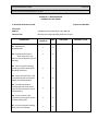


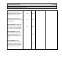


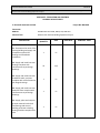

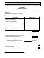


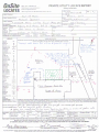


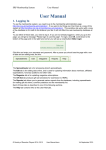

![010003E - [PROJECT.TOC] - TMG Construction Corporation](http://vs1.manualzilla.com/store/data/006000704_1-51daa2ac67e6ebfb9337b1b072f623df-150x150.png)