1
GReAT User Manual
Aditya Agrawal
Zsolt Kalmar
Gabor Karsai
Feng Shi
Attila Vizhanyo
Institute for Software-Integrated Systems
Vanderbilt University
November 2003
•
Table of Contents
1.
Introduction................................................................................................................. 1
1.1. Installation Instructions....................................................................................... 1
2. Package Contents ........................................................................................................ 2
3. Step by Step guide to using GReAT ........................................................................... 3
3.1. Transforming models from one GME paradigm to another ............................... 3
3.2. Transforming GME models to text ..................................................................... 5
4. The Tool Chain Overview .......................................................................................... 8
4.1. The GReAT Master Interpreter........................................................................... 9
4.2. The UML2XML Interpreter.............................................................................. 10
4.3. The GenerateGR Interpreter ............................................................................. 10
4.4. The GenerateConfig Interpreter........................................................................ 10
4.5. The Invoke GR Engine Interpreter ................................................................... 10
4.6. The Code Generator Interpreter ........................................................................ 10
4.7. The Library Update Utility ............................................................................... 10
5. Semantics of the Transformation Language ............................................................. 11
5.1. Rule ................................................................................................................... 11
5.2. Sequence of Rules............................................................................................. 15
5.3. Hierarchical Rules............................................................................................. 16
5.4. Branching using test case.................................................................................. 20
5.5. Parallel Execution ............................................................................................. 22
5.6. Termination....................................................................................................... 25
6. GR Engine................................................................................................................. 26
6.1. GRE.exe ............................................................................................................ 26
6.2. InvokeGRE.dll .................................................................................................. 27
7. Code Generator ......................................................................................................... 29
7.1. How to compile the generated files .................................................................. 30
7.2. How to execute the generated files ................................................................... 30
8. GR Debugger ............................................................................................................ 31
8.1. Overview: The Debugging Interface ................................................................ 31
8.2. Starting the Debugger ....................................................................................... 31
8.3. Call Stack Window ........................................................................................... 32
8.4. Debug Options on the Control Toolbar ............................................................ 32
8.5. Running Debug Mode Versus Release Mode................................................... 32
8.6. Debugger Toolbar And Menu Items ................................................................. 33
8.7. Debugger Windows .......................................................................................... 33
8.8. Halting a Program ............................................................................................. 34
8.9. Running to a Location....................................................................................... 34
8.10.
Stepping Into Rules....................................................................................... 34
8.11.
Stepping Over or Out of Rules ..................................................................... 34
8.12.
Viewing and Enabling Breakpoints .............................................................. 35
8.13.
Viewing the Call Stack for a Rule ................................................................ 35
8.14.
Viewing the Value of a Variable .................................................................. 36
•
9.
GReAT Configuration .............................................................................................. 37
9.1. High-level ......................................................................................................... 37
9.2. Low-level .......................................................................................................... 40
•
1. Introduction
The GReAT tool suite has been designed for the rapid specification and implementation
of model to model transformations. These transformations are required in many domains.
A few use case scenarios of this tools suite are:
1.1.
Developing model interpreters that convert gme models (conforming to a
metamodel)to XML files conforming to a particular dtd.
Developing model interpreters that convert gme models (conforming to a
metamodel) to a set of secondary data structures. A visitor can then be written to
convert the secondary models to text.
Developing model interpreters that convert gme models (conforming to a
metamodel) to gme models conforming to another metamodel.
Developing transformers that convert xml files belonging to one dtd to xml files
belonging to another dtd.
Developing transformers that convert xml files belonging to a dtd to gme models.
Installation Instructions
Download the latest GReAT install shield package, change log and readme from
http://www.isis.vanderbilt.edu/projects/mobies/filedownloads.asp. The readme will have
the updated list of required software and install instruction.
•
1
2. Package Contents
Languages
UML Model
1.
Transformer
2.
MetaGME
3.
UML
GReAT
4.
Config
The Graph Transformation Language
A UDM compatible MetaGME
A UDM compatible UML
A paradigm to store configuration information
(not directly used by the user)
UML Model Transformer (UMT) Interpreters
It receives information of all the file locations
and calls GenerateConfig, GenerateGR and
GReAT Master
Uml2XML. It can optionally call the Invoke
Interpreter
Engine and Code Generator interpreter
Generate GR
Converts rewriting rules to internal format
Converts configuration information to
Generate Config
GReAT Config
UML2XML
Converts the Meta information to UDM
Invoke Engine
Executes engine that performs
transformations
Code Generator
Converts transformation rules to C++ code.
Library Update
Updates references from one class diagram
package to another
MetaGME interpreters
Converts GME metamodels to a UDM
compatible UML Class diagram.
Converts GME metamodels to a UML
MetaGME2UMT package and attaches it to the provided UMT
file.
MetaGME2UML
UML interpreters
UML2XML
Command Line Tools
1.
CG.exe
2.
GRE.exe
3.
GRD.exe
Converts UML class diagrams to UDM meta
XML file
Command line version of the code generator
Command line version of the transformation
engine
Debugging GUI for the transformations
•
2
3. Step by Step guide to using GReAT
The GReAT package can be used in various scenarios. This section will give a walk
through of two typical scenarios.
3.1.
Transforming models from one GME paradigm to another
This is a scenario where there exists two GME metamodels, source and target and the
user wants to create a transformation to transform source models to equivalent target
models.
1. Open the source metamodel and invoke the MetaGME2UMT interpreter. The
interpreter prompts the user to provide the transformation file name. This can
either be a pre-existing or a new transformation file. This transformation file will
be referred to as <TF> subsequently.
2. Open the target GME Metamodel and invoke the MetaGME2UMT interpreter and
specify the same <TF> file.
3. Open the transformation file <TF> in GME. Using the Browser, you will see your
source and target GME Metamodels inserted under two packages in UML format.
The name of these package folders (a.k.a. libraries) will have the following
format:
New<Paradigm Name><Unique ID>
This decoration of paradigm names are important for the library update
interpreter, i.e. the library updater can differentiate between the new and old
paradigms using these names. The update process is described in step 6, here it is
assumed, that you inserted the Metamodels the first time.
Please remove the new and the ID part from the name. It is imperative that the
name of the folder be the same as the paradigm name.
4. You can now start to create your transformation rules. Use the Browser to insert a
Transformation folder and insert a Block model into that folder for the start rule.
The start rule can contain any number of input and output ports. These ports
represent the various inputs and outputs of the actual rule, or more precisely, the
objects in the input and output models, which are received and passed by the rule.
There should be at least one port per model that will be manipulated. For
example, in this case there will be at least two ports, one for the root object in the
input (or source) model and another for the root object in the output (or target)
model, however it is not compulsory to pass root objects, you can specify any
type of objects.
Note: These top level ports need to be named uniquely for proper execution of the
transformations.
Now you typically continue with creating subsequent blocks, test, rules, etc. in the
root rule. The transformation steps can be specified in the rules; blocks, forblocks, tests and cases rather control the sequence of the transformation steps by
specifying hierarchical and conditional organization of the rules. (For more
•
3
background information, please refer to the GReAT User Manual, Chapter 3.
Semantics of the Transformation Language)
Addition of a rule into a block consists of three steps:
• Specify the pattern by creating a reference to those Metamodel classes
which you want to participate in the pattern. Then create the pattern links
between the pattern objects. Patterns are displayed in black.
• Specify a set of objects and links you want to create or delete, similarly.
Then set the Action attribute to “CreateNew” or “Delete” of each object
and link in the set. Optionally, specify Guard or AttributeMapping code
for more sophisticated operation. Objects and links with action
“CreateNew” are colored blue, with action “Delete” colored green
automatically for visual separation from pattern objects and links.
• Specify the connection of the rule with its consisting block, first by
creating ports in the rule, then by connecting these ports with the ports of
the parent block. These directed connections represent clearly the flow of
inputs and outputs between the rules.
• The minimal proper transformation consists of the root block containing
one rule created as above. Later, as your transformation evolves, you want
to add more rules, connect and organize them hierarchically.
5. After creating the transformations you need to create a configuration. This
specifies how the transformations will be invoked by the various GR
transformation tools (GR Engine, Debugger and the Code Generator). Minimal
configuration requires the specification of
• the start rule which will be invoked first,
• the meta info; this configuration element is specified automatically by
running the “Convert transformation rules to GR format” and the “UML 2
UDM/XML” interpreters, and
• the input and output file types, which define the meta name, root folder
and file mode of the participating files.
Finally, the created configuration must be interpreted by the “Generate
Configuration file” interpreter. Please refer to Chapter 9
6. If you update your Metamodel, you need to reflect those changes in your
transformation.
Run the MetaGME2UMT interpreter again. This will create another package
in <TF> with the name New<Paradigm Name><Unique ID>.
Run Library Update ( ) and specify the old library as <ParadigmName> and
the new library as New<Paradigm Name><Unique ID>. The Library Update
utility will transfer all references to the old library/package to the new
library/package and change the old package name from <ParadigmName> to
Old<Paradigm Name><Unique ID> and change new package name to
<ParadigmName>
Delete Old<Paradigm Name><Unique ID> from <TF>
7. Different parts of the transformation model are converted into different internal
file representations.
Transformation information in converted to GR format
UML Packages and cross links are converted to UDM meta format
•
4
Configuration is converted to GReATConfig format.
The GReAT Master interpreter is used to convert the models to the required
formats.
8. After all the files have been generated the transformation can be executed either
through the GRE, InvokeEngine, GRD or through generating code from the
transformations and compiling it.
3.2.
Transforming GME models to text
This is a scenario where the user has a GME metamodel and wants to generate text in a
particular format from the models of the metamodel.
The approach to solve this problem is to create a data structure that is close to the output
text format. DOM is an example of such a data structure for the XML format. Then
specify the transformations from the GME models to the data structure and specify the
printing of the data structures to text.
1. Open the metamodel and invoke the MetaGME2UMT interpreter. The interpreter
prompts the user to provide the transformation file name. This can either be a preexisting or a new transformation file. This transformation file will be referred to
as <TF> subsequently.
2. Open a new project in the UML paradigm of GME and specify the text data
structure.
3. Open the transformation file <TF> in GME. You will see your GME Metamodel
as a package in UML format. The name of this package folder (a.k.a. libraries)
will have the following format:
New<Paradigm Name><Unique ID>
This decoration of paradigm names are important for the library update
interpreter, i.e. the library updater can differentiate between the new and old
paradigms using these names. The update process is described in step 6, here it is
assumed, that you inserted the Metamodels the first time.
Please remove the new and the ID part from the name. It is imperative that the
name of the folder be the same as the paradigm name.
4. Attach the text data structure file as a library in the <TF> file.
5. You can now start to create your transformation rules. Use the Browser to insert a
Transformation folder and insert a Block model into that folder for the start rule.
The start rule can contain any number of input and output ports. These ports
represent the various inputs and outputs of the actual rule, or more precisely, the
objects in the input and output models, which are received and passed by the rule.
There should be at least one port per model that will be manipulated. For
example, in this case there will be at least two ports, one for the root object in the
input (or source) model and another for the root object in the output (or target)
model, however it is not compulsory to pass root objects, you can specify any
type of objects.
Note: These top level ports need to be named uniquely for proper execution of the
transformations.
•
5
Now you typically continue with creating subsequent blocks, test, rules, etc. in the
root rule. The transformation steps can be specified in the rules; blocks, forblocks, tests and cases rather control the sequence of the transformation steps by
specifying hierarchical and conditional organization of the rules. (For more
background information, please refer to the GReAT User Manual, Chapter 3.
Semantics of the Transformation Language)
Addition of a rule into a block consists of three steps:
• Specify the pattern by creating a reference to those Metamodel classes
which you want to participate in the pattern. Then create the pattern links
between the pattern objects. Patterns are displayed in black.
• Specify a set of objects and links you want to create or delete, similarly.
Then set the Action attribute to “CreateNew” or “Delete” of each object
and link in the set. Optionally, specify Guard or AttributeMapping code
for more sophisticated operation. Objects and links with action
“CreateNew” are colored blue, with action “Delete” colored green
automatically for visual separation from pattern objects and links.
• Specify the connection of the rule with its consisting block, first by
creating ports in the rule, then by connecting these ports with the ports of
the parent block. These directed connections represent clearly the flow of
inputs and outputs between the rules.
• The minimal proper transformation consists of the root block containing
one rule created as above. Later, as your transformation evolves, you want
to add more rules, connect and organize them hierarchically.
6. After creating the transformations you need to create a configuration. This
specifies how the transformations will be invoked by the various GR
transformation tools (GR Engine, Debugger and the Code Generator). Minimal
configuration requires the specification of
• the start rule which will be invoked first,
• the meta info; this configuration element is specified automatically by
running the “Convert transformation rules to GR format” and the “UML 2
UDM/XML” interpreters, and
• the input and output file types, which define the meta name, root folder
and file mode of the participating files.
Finally, the created configuration must be interpreted by the “Generate
Configuration file” interpreter. Please refer to Chapter 9
7. If you update your Metamodel, you need to reflect those changes in your
transformation.
Run the MetaGME2UMT interpreter again. This will create another package
in <TF> with the name New<Paradigm Name><Unique ID>.
Run Library Update ( ) and specify the old library as <ParadigmName> and
the new library as New<Paradigm Name><Unique ID>. The Library Update
utility will transfer all references to the old library/package to the new
library/package and change the old package name from <ParadigmName> to
Old<Paradigm Name><Unique ID> and change new package name to
<ParadigmName>
•
6
Delete Old<Paradigm Name><Unique ID> from <TF>
8. Different parts of the transformation model are converted into different internal
file representations.
Transformation information in converted to GR format
UML Packages and cross links are converted to UDM meta format
Configuration is converted to GReATConfig format.
The GReAT Master interpreter is used to convert the models to the required
formats.
9. After all the files have been generated the transformation can be executed either
through the GRE, InvokeEngine, GRD or through generating code from the
transformations and compiling it.
10. To generate data in a particular text format you extend the base visitor and
implement a text dump.
•
7
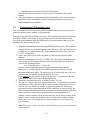
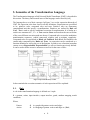
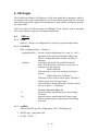
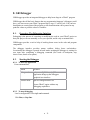
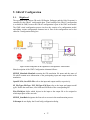
4. The Tool Chain Overview
This section describes the different interpreter, their use and their dependencies.
Figure 1 GReAT Tool Chain Overview
Interactions and steps between the tools are described as following:
Build Transformation model:
Attach all UML class diagrams using either MetaGME2UMT or by attaching
UML class diagrams as libraries. When you reattach a class diagram you can
update the references using the LibraryUpdate interpreter (LibraryUpdate.dll);
Build the transformation rules;
Build configuration model, please refer to Section 9. GReAT Configuration.
Run Transformation model:
Phase I:
Invoke GReAT Master interpreter interpreter (GReAT Master Interpreter.dll)
to generate all the required files.
Phase II:
To successfully run Phase II and Phase III, Phase I should have been successfully
executed.
Run GR Engine to perform the transformation rules on input model. This
package provides two usages of GR Engine, one is used as interpreter
(InvokeGRE.dll), while it can also be used as Win32 application (GRE.exe).
Please refer to Section 6. GR Engine.
•
8
Run GR Debugger (GRD.exe) to locate bugs in a transformation rules. Please
refer to 8. GR Debugger .
Phase III:
Run Code Generator to generate C++ code from the transformation rules. This
package provides two usages of Code Generator, one is used as interpreter
(CodeGenerator.dll), while it can also be used as Win32 application (CG.exe).
Please refer to Section 7. Code Generator.
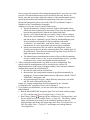
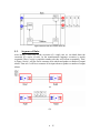
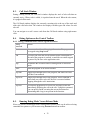
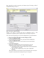
4.1.
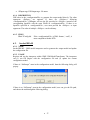
The GReAT Master Interpreter
This is the main interpreter and it can call all other interpreters. When invoked, first
a dialog box is displayed that asks for the file path and name for all the intermediate files
(see Figure 2)
Figure 2 Sample of the GReAT Master Interpreter dialog box.
The first phase of the interpretation is the generation of the different files required by the
GR Engine, GR Debugger and the Code Generator. These files are the configuration file,
transformation file and the udm meta file. These files are produced from the distinct parts
of the UMLModelTransformer language. Phase II, is optional and after the files are
created the master interpreter can invoke the GR Engine. Phase III is also optional and
can be used to invoke the Code generator.
•
9
4.2.
The UML2XML Interpreter
This interpreter works on both the UML paradigm in GME and the
UmlModelTransformer paradigm. It converts the uml class diagram into and xml
representation that is used by UDM.
If you have more that one uml package in you project it will create a file with .udm
extension. The .udm file is essentially a zip fille that contains xml files for each package.
For more information on this interpreter you can see the UDM documentation.
4.3.
The GenerateGR Interpreter
This interpreter converts the transformation rules to the GR (Graph Rewrite) format. This
format is used to decouple the high level language from the implementation of the
transformation.
4.4.
The GenerateConfig Interpreter
The Generate configuration Interpreter converts the configuration information into the
GReAT config format. This is done to again decouple the configuration information form
the UMT language. Details on this interpreter are provided in Section 9.
4.5.
The Invoke GR Engine Interpreter
This interpreter invokes the GR Engine that performs the transformations on given
input and is explained in details in Section 6.2
4.6.
The Code Generator Interpreter
This interpreter generates C++ code that implements the transformation rules and is
explained in Section 6.
4.7.
The Library Update Utility
The Library update utility is used to transfer references from one UML package to
another. In UMT UML class diagrams are added as packages. If a packages change than
you can add the new packages nd migrate all the references fro the old package to the
new package. When invoked the interpreter asks for the name of the old and new
library/uml package.
•
10
5. Semantics of the Transformation Language
The Transformation language called Universal Model Transformer (UMT) is described in
this section. The theory and research issues of the language can be found in [refs]
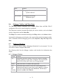
The language has a set of basic concepts. In Figure 3 we see the expression hierarchy of
UMT. An expression is the base class for all rule definitions. Expressions are specialized
to be, primitive rules, compound rules and tests. Primitive rules are elementary
computational unit that specify a transformation. Primitives are realized by Rule and
Case. Test is used to specify conditional execution of transformation. It is similar to a
switch case statement in C, C++. A Test contains Cases and based on the success/failure
of the cases different execution paths are chosen. Compound rules are used to modularize
transformation sequences, control transversal schemes and to mitigate complexity.
Compound rules are specialized to Block and ForBlock. Both Block and ForBlock can
contain other compound rules, Rules and Tests. An expression can be considered as a
function definition as well as the use of the function. In order to use a function in another
context we use ExpressionRef. ExpressionRef is a call to a function previously defined.
It can be used to define recursive structures as well as for the reuse of rules.
Figure 3 Expression Hierarchy of UMT
In the remainder the execution semantics of each expression will be explained.
5.1.
Rule
A rule in the transformation language is defined as a 9-tuple
R = (pattern, action, input interface, output interface, guard, attribute mapping, match
condition)
Where,
Pattern
Action
Æ is a graph with pattern vertices and edges.
Æ is a mapping of pattern vertices and edges to {Bind,
•
11
Input interface
Æ
Output
interface
Guard
Æ
Æ
Attribute
mapping
Æ
Match
condition
Æ
CreateNew, Delete} the set of actions
is a set of distinct input ports that can receive graph
objects from previous rules
is a set of distinct output ports that will transfer graph
objects of this rule to the next rule.
is an OCL expression that’s evaluates on a match of the
LHS pattern to return true or false. If this expression is
true only then will the rule fire for that match otherwise
the next match will be considered.
are arithmetic and string expressions that are evaluated
for each valid match to generate the values of edge and
vertex attributes.
can be either “all matches” or “any match”. If it is “all
matches” for each input packet the rule will find all the
matches and for all the valid matches it will execute the
effecter. If it is “any match” then for each packet the rule
will find the first valid match and call the effecter for
that match. The match chosen is non-deterministic.
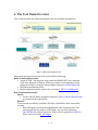
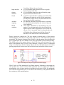
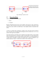
Figure 4 shows an example rule. The rule contains a pattern graph, a Guard and an
AttributeMapping. Each object in the pattern graph refers to a class in the heterogeneous
metamodel. The semantic meaning of the reference is that the pattern object should match
with a graph object that is an instance of the class represented by the metamodel entity.
The default action of the pattern objects is Bind. The New action is denoted by a tick
mark on the pattern vertex (see the vertex StateNew in figure). Delete is represented
using a cross mark (not shown in figure). The In and Out icons in the figure are used for
passing graph objects between rules and will be discussed in detail in the next section.
Figure 4 An example rule with patterns, guards and attribute mapping
GReAT relies on UML metamodels for defining patterns. Furthermore, the patterns are
also specified in (a superset of the) UML syntax and since the modeler uses UML for
metamodeling, as it was more intuitive to describe the rules also in UML. By making the
user reference each pattern object we can enforce the consistency of the patterns and thus
the consistency of the transformations.
•
12
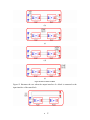
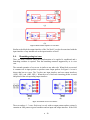
Figure 5 Start of a rule fire sequence with 2 input packets
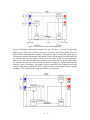
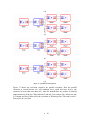
Figure 5 till Figure 9 shows the execution of a rule. In Figure 5 we have two incoming
packets to the rule. The execution of the rule will start with the first packet. The first
packet will be used to produce matches for the pattern. Figure 6 shows the production of
two matches from the first packet. Each match is tested wit the guard expression and only
the matches that have the guard evaluate to true are kept. Then for each match new
objects are created and matched objects deleted according to the rule specification. After
the creation and deletion of the objects the attribute mapping is invoked that add and
modifies values of attributes. The pattern objects connected to the output port are then
used to create output packets base on the matched and/or created graph objects as shown
in Figure 7. The same process is repeated with the second packet.
•
13
Figure 6 Rule has a set of matches for first input packet
Figure 7 a set of output packets generated for each match
Figure 8 matches for the second input packet
•
14
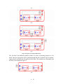
Figure 9 final state after the execution of the rule
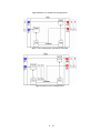
5.2.
Sequence of Rules
After having a clear idea of the execution of a single rule we can think about the
execution of a series of rules. In the transformation language execution is mainly
sequential. Thus if a rule is coupled to another rule they will execute sequentially. Thus,
in Figure 10 rule 1 will fire first to consume all its tokens and produce a number of output
tokens. Then rule 2 will fire to consume all its input tokens to produce a number of output
tokens.
(a)
(b)
•
15
(c)
Figure 10 Firing of a sequence of 2 rules
5.3.
Hierarchical Rules
There are two types of hierarchical rules.
Block
For Block
Both the hierarchical rules have the same semantics with respect to rules connected to
and from it. Thus if in Figure 10 the rules 1 and 2 were hierarchical even then they would
have has the same action as described there. The semantics within a hierarchical rule
differs.
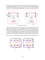
A block is a container that encapsulates a number of rules. The block has the semantics
that it will push all its incoming packets through to the first internal rule. So it is very
similar to the regular rule semantics.
The output interface of the block can be attached to the output interface of any internal
block or the input interface of the block. In other words the block can send output packets
from any internal rule or pass its input packets as output. However, the output interface of
a block must be attached to exactly one interface and it cannot be attached to two
different interfaces. Figure 11 shown the execution of rules within a block.
(a)
•
16
(b)
(c)
(d)
(e)
Figure 11 Rule execution of a Block
Figure 12 illustrates the case when the output interface of a block is connected to the
input interface of the same block.
•
17
(a)
(b)
(c)
(d)
Figure 12 Sequence of execution within a block
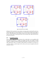
The “for block” has different semantics within. If we have n incoming packets in a “for
block” then the first packet will be pushed through thru all its internal rules to produce
output packets and then the next packet will be taken. The semantics are illustrated with
the help of an example in Figure 13.
(a)
•
18
(b)
(c)
(d)
(e)
(f)
•
19
(g)
(h)
Figure 13 Rule execution sequence of a "for block"
Similar to the block the output interface of the “for block” can also be associated with the
input interface of any internal rule or the input interface of itself.
5.4.
Branching using test case
There are many scenarios where the transformation to be applied is conditional and a
branching construct is required. Thus the branching construct supported by us is a test
case.
The external semantics of a test case is similar to any other rule. When fired or executed
it consumes all its input packets to produce some output packets. In Figure 14 a test is
shown that has two cases. The Test has one input interface and two output interfaces
({OR1, OP1} and {OR2, OP2}). When the test is fired each incoming packet is tested
and placed in the corresponding output interface.
(a)
(b)
Figure 14 Execution of a test case construct
The test can have 1..* cases. Each case is a rule with no output pattern and no actions. It
contains an LHS pattern a guard condition and an input and output interface. If the LHS
•
20
pattern has a match the case succeeds and the input packet to the case is passed along. If
the pattern has no matches then the test fails. Alternatively if the match doesn’t satisfy the
guard condition even then the case fails. Figure 15 shows a case with a successful
execution. The input packet has a valid match and so the packet it allowed to go forward.
(a)
(b)
Figure 15 Execution of a case
When a test has many cases then each input packet is checked with each case to see
which cases are satisfied for the particular packet and the packet is placed in the output
interface of each satisfied case. The order of testing cases is derived from the physical
placement of the case within the test. The cases are evaluated from top to bottom. If there
is a tie in the y co-ordinate then the x co-ordinate is used from left to right. There fore the
comparison is made ascending order of y and if two y are same then in ascending order of
x. The case also has another attribute called the cut. When enabled it means that if the
case succeeds for a given packet then the packet should not be tested with the other cases.
(a)
(b)
•
21
(c)
(d)
(e)
Figure 16 Execution of a test condition
In Figure 16 the execution of a test is shown. An input packet is replicated for each case.
Then the input packet is tried with the first case, it succeeds and is copied to the output of
the case. Then the packet is tried with the second case, this time it fails and the packet is
removed. Finally after all input packets have been consumed the output interfaces have
the respective packets.
5.5.
Parallel Execution
When a rule is connected to more than one rule or when there is a test condition with
more than one path then it is called as the parallel execution. The parallel execution
semantics is defined such that the different parallel paths can execute exclusive to each
other and thus the order of execution of these paths are not defined. If executed on a
sequential machine a particular path will be chosen and executed completely before the
next path is chosen.
•
22
(a)
(b)
(c)
•
23
(d)
(e)
(f)
(g)
Figure 17 A parallel execution sequence
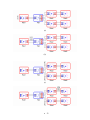
Figure 17 shows the execution sequence for parallel execution. Here the parallel
execution is caused because of a test condition but it could also have been a rule
connected to more than one other rule. After the branch there are packets at both the
output interfaces of the test. Thus both rule 2 and rule 4 are ready to fire, in this case rule
2 is chosen and fired, followed by the execution of following rules. This ends at rule 3.
Then rule 4 & 5 are fired.
•
24
5.6.
Termination
The final item to discuss is the termination. A rule sequence is terminated either on a rule
having no output interface or on a rule with having an output interface but not producing
any packets.
Thus if the firing of a rule produces zero output packets then the rules following it will
not be executed. Hence in Figure 17 if rule 4 produced zero output packets then rule 5
would not have been fired. However, the there should be a construct to sequence rules
without having to bind the ports.
•
25
6. GR Engine
The Graph Rewrite Engine (GR Engine) is a fully meta-model-driven interpreter which is
developed to take in the configuration file, get all meta-models dynamically for accessing
input and output models, apply the transformations to input models, and directly generate
the output model.
GReAT provides two different usages of GREngine. It can either be used as command
line or be invoked as interpreter for transformation model.
6.1.
GRE.exe
6.1.1. NAME
GRE.exe – directly use configuration file as input to generate output model
6.1.2. SYNOPSIS
GRE <configurationFile> [<fileSpec>] ……
<configuraitonFile> the name of the configuration file (“.mga” or “.xml”)
generated by the interpreter GenerateConfig on the
GReAT configuration model created with GReAT
language.
< fileSpec >
the string to specify the file with file Id and file
name. If the file mode is read only, or write only, or
read and write, the format is:
FileID=FileName
If the file mode is read, write and copy, the format
must be:
FileID=FileName1;FileName2
FileName1 will be used to read in model, FileName2
will be used to write and copy model.
If the FileName contains white space characters, then
the use of quotes “ ”is obligatory.
-d
-dv
For more info read Chapter 10
print out run time transformation rule name during
execution
print out run time transformation rule name, input
packets, pattern matches, output packets info during
execution
6.1.3. SAMPLE
GRE.exe SF2FSF.mga SF=“SFInput.mga” FSF=“FSFOutput.mga”
SF2FSF.mga : configuration file
SF, FSF : file ID
•
26
SFInput.mga, FSFOutput.mga : file name
6.1.4. DESCRIPTION
GRE takes in the <configurationFile> to generate the output model directly. The other
arguments <fileSpec> are optional. If there are <fileSpec>s following
<configurationFile>, GREngine will use the file provided in <fileSpec> instead of the
corresponding InputFile with the same FileID in <configurationFile>. If there is no
InputFile specified in <configuratioFile>, user must provide the <fileSpec> as input
arguments. The order of multiple <fileSpec> can be arbitrary.
6.1.5. FILES
GReATConfig.dtd
6.2.
If the <configurationFile> is XML format ( “.xml”), it
must compliant with this DTD.
InvokeGRE.dll
6.2.1. NAME
InvokeGRE.dll – GME model interpreter used to generate the output model and update
the configuration file.
6.2.2. USAGE
Register and run the interpreter within GME/ UMLModelTransformer. The interpreter
can (1) run GR Engine with the configuration file and (2) update the current
configuration model.
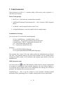
If there is “NoPrompt” atom in the configuration model, then the following dialog will
pop up:
If there is no “NoPrompt” atom in the configuration model, user can give the file path,
and choose the task through the following dialog:
•
27
•
28
7. Code Generator
Code Generator is a GR to C++ translator utility, which can be used to generate C++
code from your GR rules.
What is in the package
1. bin/CG.exe - Code Generator command line executable
2. UMLModelTransformer/CodeGenerator.dll - Code Generator GME interpreter
add-on
3. etc/GR.dtd - must be in path for able to run CG.exe
4. etc/InputFileRegistry.h - must be in path for able to compile output
Command line tool usage
You can execute CG.exe from the command prompt.
CG.exe <GenFileName> <ConfigFileName> [-m|-t]
GenFileName - the generated rewriting code file name base.
ConfigFileName - GReAT Configuration information file.
[-m] Generate the main.cpp file only.
[-t] Generate the translator files only.
Examples:
CG.exe SF2FSF SF2FSFConfig.mga
CG.exe generated\HSM2FSM HSM2FSMConfig.mga -t
The translator files consist of the code which perform the transformation specified in
your rules. The generated main.cpp file drives this translator code by opening and/or
creating the models related to the translation and assigning input objects to the start
translation rule.
GME interpreter usage
Just click on the icon
on the GME interpreter toolbar. Be sure, that the configuration
is saved prior to executing the Code Generator interpreter. (See more info in Chapter 8.).
If you did not specify runtime info in your configuration, the main.cpp file will not be
generated. The translator files are always generated.
TranslatorLog.txt – This is log file created by Code Generator consisting helpful
information of the generating process. Compiler warnings and errors are reported here.
•
29
7.1.
How to compile the generated files
Here are the steps needed to compile the generated files:
1. Create a Win32 Console Application project in VS
Open Microsoft Visual Studio, select File/New.. and choose Win32 Console
Application from the Project tab. Select Empty Project in the next dialog.
2. Add files into project
Select Project/Add to Project/ Files..., and add the generated files to the project.
The Udm.exe generated meta API files also must be added to the project. It is a
good idea to copy all these files into the project directory, and add them from
there. etc\InputFileRegistry.h is a common source file and must be always added
to your project.
3. Set project settings
Select Project/Project Settings., go to the C/C++ tab.
Select Category: "Code Generation" and set
• "Debug Multithreaded DLL" for Win32 Debug configuration
• "Multithreaded DLL" for Win32 Release configuration
Select Category: "Preprocessor" and add the following directories into
"Additional include directories", for all configurations:
$(UDM_PATH)/include, $(UDM_PATH)/3rdparty/stl,
$(GREAT_PATH)/etc
Go to the Link tab, select Category: "Input, and add the following directories into
"Additional Library path", for all configurations:
$(UDM_PATH)/lib,$(UDM_PATH)/3rdParty/zlib,$(UDM_PATH)/3rdPa
rty/xerces/xerces-c2_2_0-win32/lib
Also, add the following libraries into Object/library modules:
• for Win32 Debug configuration: UdmBase_D.lib UdmGME_D.lib
UdmDom_D.lib UdmUtil_D.lib xerces-c_2d.lib zlibD.lib
• for Win32 Release configuration: UdmBase.lib UdmGME.lib UdmDom.lib
UdmUtil.lib xerces-c_2.lib zlib.lib
7.2.
How to execute the generated files
If the compile was successful, the resulted .exe can be executed by either specifying the
-d default switch, or specifying non-default input files as command line arguments. For a
full example of the usage of command line arguments please see Chapter 10. For every
.mga input file the corresponding meta models must be registered in GME, and for every
.xml input file the corresponding meta dtd files must be in path.
•
30
8. GR Debugger
GRDebugger provides an integrated debugger to help locate bugs in a GReAT program.
GRDebugger has all the basic features that any programming language’s debuggers could
have: you can execute your GReAT program step by step, i.e. rule by rule. You can have
breakpoints at certain point of the program, so the transformation can be paused at any
point the values to peek the values of variables.
8.1.
Overview: The Debugging Interface
Debugging is the process of correcting or modifying the code in your GReAT project so
that your project can run smoothly, act as you expected, and be easy to maintain later.
GRDebugger provides a tool to help of tracking down errors in the code and program
components.
The debugger interface provides menus, toolbars, dialog boxes and windows.
Occasionally the debugger is paused in break mode, meaning the debugger is waiting for
user input after completing a debugging command (like break at breakpoint, step
into/over/out, break at exception).
8.2.
Starting the Debugger
8.2.1. To start the application
From command line,
Mode
Features
Debug mode
grd.exe configFileName [-d] The
application brings up the debuggers
graphical user interface.
Release mode
grd.exe configFileName -nd
It runs GReAT engine without any
debugging capabilities.
8.2.2. To start debugging
Load a configuration file using Load command.
Click Run, or Step Into.
•
31
8.3.
Call Stack Window
During a debug session, the Call Stack window displays the stack of rule calls that are
currently active. When a rule is called, it is pushed onto the stack. When the rule returns,
it is popped off the stack.
The Call Stack window displays the currently executing rule at the top of the stack and
older rule calls below that. The window also displays variable types and values for each
rule call.
You can navigate to a rule’s source code from the Call Stack window using right mouse
click.
8.4.
Debug Options on the Control Toolbar
8.4.1. Debug Commands that Control Program Execution
Debug
command
Action
Execute
Executes code without debugging information. The program can
be stopped using Stop button.
Run
Executes code from the current statement until a breakpoint or
the end of the program is reached, or until the execution stopped
or paused by the user or the application exits.
Stop
Terminates the execution either in Debug mode or in Release
mode.
Pause
Halts the program at its current location.
Step Into
Single-steps through rules in the program, and enters each rule
call that is encountered.
Step Over
Single-steps through rules in the program. If this command is
used when you reach a rule call, the rule is executed without
stepping through the rule's instructions.
Step Out
Executes the program out of a rule call, and stops on the rule
immediately following the call to the rule. Using this command,
you can quickly finish executing the current function after
determining that a bug is not present in the function.
8.5.
Running Debug Mode Versus Release Mode
When you invoke GRDebugger both a Debug and a Release mode can be achieved using
command line options or you can start using Execute button from toolbar.
•
32
8.6.
Mode
Features
Debug mode
Debugging information in is stored.
Speed is reduced.
Release mode
No debugging information
Maximum speed
Debugger Toolbar And Menu Items
The File menu contains commands such as Open, Close, Save and Exit. GReAT
configuration files can be opened using these commands.
The View menu contains commands that display the various windows, such as the Stack
window, Log window and the Status Bar.
The Help menu contains commands that display the Help window or the About window.
Commands for debugging can be found on the control toolbar and the breakpoint toolbar.
These commands start the debugging process (Go, Step Into, Step Out, Step Over,
Run).
8.7.
Debugger Windows
Three specialized windows display debugging information for your program. You can
access these windows using the View menu.
The following table lists the debugger windows and describes the information they
display.
8.7.1. Debugger Windows
Window
Displays
Log
Information about the loading, saving and execution, including
loading, running or saving errors, exceptions. The executed rule
names will be shown here in the case of Log command.
Source
Names and values of variables and expressions.
Call
Stack
and
Variables
Information about variables used in the current and previous
statements and function return values (in the Auto tab), variables
local to the current function (in the Locals tab), and the object
pointed to by this (in the This tab).
•
33
Debugger windows can be docked or floating.
When a window is in floating mode, you can resize or minimize the window to increase
the visibility of other windows.
8.8.
Halting a Program
8.8.1. To halt execution
Click Pause on the control toolbar and the control will return to GRDebugger
8.9.
Running to a Location
8.9.1. To run until a breakpoint is reached
Set a breakpoint.
On the tool bar, click Run button.
8.10.
Stepping Into Rules
8.10.1. To run the program and execute the next rule (Step Into)
While the program is paused in break mode (program is waiting for user input after
completing a debugging command), click Step Into on toolbar.
The debugger executes the next rule, then pauses execution in break mode. If the next
statement is a rule call, the debugger steps into that rule, then pauses execution at the
beginning of the rule.
Repeat step 1 to continue executing the program one rule at a time.
8.10.2. To step into a specific rule
Set a breakpoint just before the rule call.
Use the Run, Step Into, or Step Over command to advance the program execution to
that point.
8.11.
Stepping Over or Out of Rules
8.11.1. To step over a rule
Open a source file, and start debugging.
Execute the program to a rule call.
On the Debug menu, click Step Over.
The debugger executes the next rule, but pauses after the rule returns.
Repeat step 3 to continue executing the program, one statement at a time.
•
34
8.11.2. To step out of a rule
Start debugging, and execute the program to some point inside the rule.
On the Debug menu, click Step Out.
The debugger continues until it has completed execution of the return from the
rule, then pauses.
Caution In general, to avoid very slow execution, you should not step out of a rule
containing a loop. Instead, you should set a breakpoint at the end of the rule, and then
choose Go from the Debug menu to execute to the end of the rule. Then choose Step
Out.
8.12.
Viewing and Enabling Breakpoints
8.12.1. To set a breakpoint
In the source code window, select the line containing the breakpoint you want to
enable.
Click the Toggle Breakpoint toolbar button.
A red dot appears at selected line in the left margin of the source window.
8.12.2. To remove a breakpoint
For a location breakpoint in a source code window, select the line containing the
breakpoint you want to disable.
Click the Toggle Breakpoint toolbar button.
For a location breakpoint, the red dot in the left margin disappears.
8.12.3. To view the list of current breakpoints
On the toolbar, click Show All Breakpoints button.
8.12.4. To remove all breakpoints
Click the Remove All Breakpoints toolbar button.
8.13.
The red dots in the left margin disappear.
Viewing the Call Stack for a Rule
8.13.1. To view the call stack for a rule
Place a breakpoint in the rule.
On the toolbar, click Run to execute your program to the location of the
breakpoint.
On the View menu, click Stack if the stack window is not visible.
•
35
The calls are listed in the calling order, with the current rule (the most deeply
nested) at the top.
8.13.2. To change the call stack display
Double click on a Rule name expands all the variable types in that rule context.
Double click on a variable type name will expand all the variable of that type.
Double click on a variable name will expand all the variable values. If a value is
empty it probably has empty string name.
8.14.
Viewing the Value of a Variable
To view the value of a variable
Wait for the debugger to stop at a breakpoint.
– or –
Click Pause on the toolbar.
Find the variable in the Stack window.
To view the value of a variable using right click
When the debugger is stopped at a breakpoint, switch to a source window, and
click the right mouse button on the line declaring the variable.
Select the variable.
To view type information for a variable in the Stack window
In the Stack window, find the variable and see its parent.
•
36
9. GReAT Configuration
9.1.
High-level
The operation of the various GR tools (GR Engine, Debugger and the Code Generator) is
controlled by the GReAT configuration data. Visual setting of the GReAT configuration
is available in GME, because the GReAT configuration is part of the UMT meta model.
The GME visual configuration process involves the creation of a configuration model,
and adding various configuration elements into it. Part of the configuration can be also
edited in a configuration dialog box.
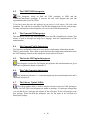
Figure 18 Visual configuration for the ‘Signal Flow to Flat Signal Flow’ transformation
Short description of the UMT Configuration elements follows:
SF2FSF_MetaInfo::MetaInfo contains the GR translation file name and the name of
file which contain meta information of the participating input and output models in the
translation.
OpenSF::File, SaveFSF::File refer to the input and output models, respectively.
SF_FileType::FileType, FSF_FileType::FileType refer to the input and output model
types. Define the meta name, root folder and file mode of the corresponding file.
File::FileObject define which objects in the input or the output file to be assigned to
which input ports of the start rule.
SF2FSF_StartRule designates the first rule to execute in the transformation process.
NoPrompt do not display the GreatConfig configuration dialog.
•
37
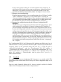
Input, output files can also be selected by the Windows Open File Dialog in GReAT
Configuration Dialog. See Fig. 8.2.
Figure 19 he GReAT Configuration Dialog
Changes in the dialog are reflected back into the configuration model, i.e. after
completion the configuration model is updated with the selected input/ output files.
Here is the step by step guide how to create the configuration for your transformations:
1. Open your existing UMT model you want configure in GME.
2. Create a Configurations folder.
Select the Root Folder in the Browser, select Insert Folder/Configurations.
3. Create a Configuration model.
Select the Configurations folder created in Step 2 and select Insert Model/
Configuration.
4. Set the Meta information.
Drag & drop a MetaInformation atom from the Part Browser into the
Configuration model created in Step 3. Set the following attributes:
• Transformation GR file: output file name of the “Convert transformation
rules to GR format” interpreter.
• Udm Project File: output file name of the “UML 2 UDM/XML”
interpreter.
Note: These attributes are not needed to be specified manually, they are going to
be updated automatically after running the respective interpreters.
•
38
5. Set the Usage information.
Setting the usage information consist of the start rule selection, and the
assignment of input model objects to input ports of the start rule.
a. Select the start rule.
Drag & drop a StartRule proxy into the Configuration model. Drag & drop
any existing rule from your Transformation folder on the StartRule proxy.
b. Assign objects to input ports.
Drag & drop a FileType model into the Configuration model. Each
FileType model represents a template for an input model. A file type
model contains only meta information of the corresponding input model.
The separation of FileType-s from actual File-s is very practical, because
it makes the abstraction of the input object assignment possible: instead of
specifying real objects in a specific input file, you specify object path in a
type of input files. The object path is a semi-colon separated expression,
where each expression element specifies an object type, starting from the
type of the root folder.
• Create a FileObject atom in the FileType model and specify the
object path attribute of it.
• Connect the created FileObject atom to the input port of the start
rule, which input port you want the FileObject assigned to.
Also, set the following FileType attributes:
• Meta name: input (output) model paradigm name.
• Root class name: root name of model paradigm.
This must match with the first object type of the object path
attribute specified in all of the contained FileObject-s.
• File mode: File operation semantics:
o Read: open read-only.
o Write: open write-only (create new or overwrite
existing).
o Read and write: open read-write (open and update
existing).
o Read and write to a copy: open existing file and
save under a different file name.
• DTD pathname: if the model paradigm is an .xml file, the path of
the corresponding .dtd file.
6. Set the Runtime information
Specify the actual input and output models of the transformation. Drag & drop a
File atom for each input and output model into the Configuration model, and set
the following attributes:
• File path name: Read/Write file name of the model depending on the
selected File mode in the connected FileType attributes.
• Copy path and name: Specify only if ‘Read and write to a copy’ File mode
is selected in the connected FileType attributes. The opened filed is saved
under this file name.
Finally connect the corresponding File-s and FileType-s.
•
39
If you want to generate code by the “Generate code from rules” interpreter, the
specification of the Runtime information is not obligatory, although specifying it
enables the CG to generate a main.cpp file, which can open & save the files
specified in the Runtime information by default. See chapter 6 for more details.
7. Interpret your transformation
If you have not executed the “Convert transformation rules to GR format” and the
“UML 2 UDM/XML” interpreters yet, execute them prior to executing the
“Generate Configuration file” interpreter. These interpreters update automatically
your configuration meta information as described in step 4, which changes must
be reflected in the output of “Generate Configuration file” interpreter.
8. Interpret the configuration data by the “Generate Configuration file”
interpreter
The GR tools accept configuration models in the GReATConfig paradigm, which
can be generated by executing the “Generate Configuration file” interpreter. If
you have multiple configurations specified in your Configurations folder, be sure
to select the Configuration model you want to interpret. In case you have only one
configuration model specified, that one will be interpreted regardless of the actual
selection. After interpretation completed, the ‘Config file path name’ attribute of
the interpreted Configuration model is filled automatically with the generated
config file name. Now you can execute the GR Engine on your transformation, or
after specifying the ‘Filename base for Code Gen’ attribute, you can also execute
the Code Generator interpreter. Failing of specifying this ‘Filename base for Code
Gen’ attribute results in the code generation with default file name ‘.\output.cpp’
and ‘.\output.h’.
The ‘Transformation GR file’ and ‘Udm project file’ attributes specified in step 4 can be
either in absolute or relative path format. If relative path is used, the specified attribute is
considered relative to the generated config file path. E.g. if config file path is
‘c:/GReAT/Conf/config.mga’
and the ‘Transformation GR file’ attribute is
‘../Trans/trans-gr.xml’ then the GR tools will search for the transformation file in ‘C:/
GReAT /conf/../Trans’ or equivalently in ‘c:/ GReAT /trans’. Similarly, if the ‘Udm
project file’ attribute is ‘../Meta/meta.udm’ then the project file is given by ‘c:/
GReAT/Meta/meta.udm’.
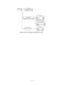
9.2.
Low-level
The output of the “Generate Configuration file” interpreter is yet another model. This
intermediate model format called GReATConfig is the direct configuration input for the
GR tools.
There is no need of manually editing this file, however it might be useful to be familiar
with the GReATConfig meta model, which is depicted below.
•
40
Figure 20 The GReATConfig meta model in UML notation
•
41
10. Specifying Command Line Arguments
The command line version of GRE and the generated code take command line arguments
to open/create/save input and output models. Two examples are provided to illustrate
how to specify these arguments.
10.1.
Example 1
Suppose, you want configure the SignalFlow 2 FlatSignalFlow UmlModelTransformer
model by specifying an input SignalFlow model and an output FlatSignalFlow model.
This can be configured by creating two FileType atoms, :
one for the SignalFlow model (fileID: “SF”) with action read
and another one for the FlatSignalFlow ( fileID: “FSF) model with action
write
Then, GRE or the CG generated code will take the following arguments:
SF=”SFInputModel.mga” FSF=”FSFOutputModel.mga”
where
the order of SF and FSF arguments can be arbitrary
If either file name contains white space characters, then the use of quotes “ is
obligatory, otherwise the file name will be split into two arguments.
If the file name does not contain white space characters, the use of quotes “ is
optional.
Any command line argument is considered legal, if the expression to be parsed
has two strings separated by the equal character “=”. The string literal before
“=” is the fileID, the string literal after “=” is the filename.
CG generates main code which is able to provide default arguments. The
default arguments are meaningful only if the runtime information is specified
in the GReATConfig model. The generated main.cpp behaves differently on
the number of command line arguments:
o If no arguments found, the usage of the program is printed out to the
console.
o If –d argument found, then the default arguments (specified in runtime
information in the GReATConfing model) will be parsed and used in the
program.
o Otherwise each argument is going to be parsed and used in the program.
The user must specify only those input files (identified by file IDs), which are not default.
E.g. if he want use SF=”SFInputModel.mga” always but with different output FSFs, he
can call specify FSF=”myFSFOutputModel.mga” only.
If invalid expression found by the parser, exception is thrown. (“Invalid input file
expression: <expr>” printed to the console)
•
42
10.2.
Example 2
Configuring HSM2FSM involves specifying creating one FileUsage atom with action
ReadWriteCopy (rwc). An input StateChart model gets read, and an output StateChart
model is created, copied and saved by the generated code.
Then, GRE or the CG generated code will take the following arguments:
SC=”inputSC.mga”;”outputSC.mga”
-
here quotes can be omitted as well, but do not forget to specify the separator
“;”, because if you miss out “;” the entire expression after “=” is considered to
be filename.
The parser is able to ‘eat’ any white space characters around the separators
“=” and “;”. This seems to be not useful in specifying command line
arguments, because then the argument is split into two separate arguments.
•
43