1
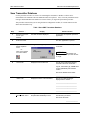
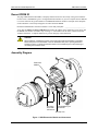
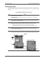
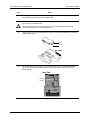
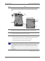
Smart Multivariable Transmitter (SMV 3000)
Main PWA Replacement Kit Instruction
Main PWA (Part number 51404205-503)
PROM (Part number 51197486-TAB)
Document
Form: 34-SM-33-03
Effective: 09-01
Supersedes: None
Summary
This instruction assumes that you are somewhat familiar with SMV 3000 transmitters and so it is designed
to aid you in the replacement of the Main Printed Wiring Assembly (PWA) of your SMV 3000 Smart
Multivariable Transmitter. The procedures detail the removal and replacement of the Main PWA.
The replacement Main PWA (and associated PROM to be installed on the Main PWA) is a direct
replacement for the existing PWA and PROM in your SMV 3000 transmitter.
ATTENTION
Once the Main PWA has been replaced, the transmitter will require a bench calibration using
precision ABSOLUTE pressure equipment and/or precision DRAFT pressure equipment,
depending upon the transmitter model. Refer to the SMV 3000 User’s Manual for the correct
procedure.
Tools Needed
You will need the following tools and equipment to perform the replacement procedures:
•
SCT 3000 Smart Configuration Toolkit software application loaded on a laptop PC
•
3mm Allen wrench
•
Medium flat-blade screwdriver
•
Medium phillips screwdriver
ATTENTION
This equipment contains devices that can be damaged by electrostatic discharge. It is
imperative that assemblies containing static-sensitive devices are carried in conductive plastic
bags. When adjusting or performing any work on such assemblies, electrostatic discharge
(ESD) mats, grounded workstations, and wrist straps must be used.
Form 34-SM-33-03
Page 1 of 7
SMV 3000 Transmitter
Main PWA and PROM Replacement
Save Transmitter Database
Use the procedure in Table 1 to create a file containing the transmitter’s database so that it can be
downloaded to the transmitter after the Main PWA has been replaced. Also, record any transmitter status
messages and the PROM serial number for reference before you begin the replacement procedure.
This procedure assumes that you are using the Smart Configuration Toolkit, SCT 3000 connected to the
SMV 3000 transmitter loop.
Table 1 Save SMV Transmitter Database
Step
Click on . . .
1
SCT.exe or the SCT
icon on your
desktop.
2
Enter user name.
3
Upload from the
Device dropdown
menu
- or Click on the Upload
icon in the toolbar.
Dialog box showing the upload action.
“Device”Tab
Displays the Device tab card.
4
Display
SCT title window is displayed.
Result or Action
A user name is required to open SCT
application.
The SCT application is opened.
The transmitter database is uploaded
to the SCT.
ATTENTION Be patient, this
operation may take up to five minutes
or longer.
The tab card contains the following
information about the transmitter:
Tag ID, Transmitter type, PROM serial
number (PROM ID) and Firmware
version.
Record the PROM serial number:
____________________________
5
“Status” Tab
Displays the status of the transmitter.
Record any status messages
displayed in the window:
____________________________
____________________________
____________________________
____________________________
6
Save As from the
File dropdown menu.
Dialog box that allows you to name a
file (transmitter database) to save.
The transmitter database is saved as a
SCT file that you named.
Record the file name:
________________
Page 2 of 7
Form 34-SM-33-03
Main PWA and PROM Replacement
SMV 3000 Transmitter
Record PROM ID
The plug-in PROM on the Main PWA is uniquely characterized to the meter body of the given transmitter.
For this reason, each PROM is given a 10-digit identification number so you can verify that the new PROM
is a correct match for the given transmitter. The PROM identification number is stamped on the nameplate
on the transmitter’s meter body and appears on a label under the PROM.
Record the PROM number from the transmitter’s meter body nameplate: __________________________
Verify that the number on the new PROM label matches the number on the transmitter’s meter body, and
the PROM serial number recorded in step 4 on Page 2. If the numbers do not match, contact Honeywell
Technical Assistance. Telephone numbers are given on last page of this instruction.
CAUTION
When installed in a hazardous location, keep covers tight while the transmitter is energized.
Disconnect power to the transmitter in the non-hazardous area prior to opening electronics
housing for service, or determine that the location is non-hazardous prior to disconnecting or
connecting the transmitter wires.
Assembly Diagram
Electronics
Module
Flex Tape
and Power
Connectors
Temperature Input
Connector
End-cap Lock
Figure 1 SMV Electronics Module and Connectors
Form 34-SM-33-03
Page 3 of 7
SMV 3000 Transmitter
Main PWA and PROM Replacement
Replacing Main PWA
The electronics module inside the SMV electronics housing consists of two PWAs: The Main electronics
PWA and the Temperature PWA. The PWAs are attached to each other by screws, a plastic bracket and a
connector.
Table 2 SMV Main PWA Replacement Procedure
Step
1
Action
Remove power from the transmitter.
We recommend that you remove the transmitter from service and move it to a clean area
before taking it apart
2
Loosen end-cap lock (3mm Allen wrench) on the electronics side of the electronics housing
and unscrew the end cap. See Figure 1.
3
Release metal retaining clip from underside of electronics module. Refer To Figure 1.
•
Unplug flex-tape connector and power connector from electronics module.
•
Unplug temperature input connector from Temperature PWA on underside of module.
4
Loosen two captive mounting screws on topside of electronics module and carefully pull
module out from transmitter housing.
5
Remove screw holding the plastic bracket and retaining clip to Main PWA and remove bracket
from Main PWA. See figure. Note that the end of temperature PWA engages slot in bracket.
Main PWA
Retaining
Clip
PWA
Connector
Screw
Plastic
Bracket
PROM
Location
Temperature PWA
PWA
Connector
Screw
Screw
Procedure continued on next page ⇒
Page 4 of 7
Form 34-SM-33-03
Main PWA and PROM Replacement
SMV 3000 Transmitter
Step
Action
6
Referring to figure in Step 5. Remove two retaining screws and carefully pull Temperature
PWA straight up to disconnect it from the Main PWA.
7
With component side of the new Main PWA facing up, locate PROM socket on PWA. See
figure in step 5 for PROM location.
We recommend that you use a ground strap or ionizer when handling the PROM, since
electrostatic discharges can cause PROM failures.
8
Align notch and Pin 1 of new PROM with the notch in IC socket on new Main PWA. Carefully
plug PROM into socket.
Pin 1
Notch
Main PWA
9
Be sure that write protection jumper is in the desired position. Also check if failsafe jumper is
cut or intact as desired. See SMV 3000 User’s Manual for details on write protection and
failsafe settings.
Main PWA
Failsafe
Jumper
Write
Protect
Jumper
Procedure continued on next page ⇒
Form 34-SM-33-03
Page 5 of 7
SMV 3000 Transmitter
Main PWA and PROM Replacement
Step
10
Action
Align PWA connector on Temperature PWA over the connector on Main PWA and slide
connector pins through Temperature PWA connector. See figure. Replace two retaining
screws and secure Temperature and Main PWA to bracket (located on underside of Main
PWA).
Main PWA
Flex Tape
Connector
Power
Connector
Retaining
Clip
PWA
Connector
Temperature PWA
Temperature
Input
Connector
PWA
Connector
Screw
Screw
11
Replace plastic bracket and retaining clip over ends of Main PWA and Temperature PWA.
Note that the end of Temperature PWA engages slot in bracket. Secure with a screw.
12
Carefully insert electronics module back into transmitter housing. Secure to housing with the
two captive mounting screws on topside of electronics module.
13
Refer to figure in step 10 and Figure 1.
•
Reconnect temperature input connector to Temperature PWA on underside of module.
•
Reconnect flex-tape connector and power connector to Main PWA.
•
Secure metal retaining clip on underside of electronics module.
ATTENTION
Once the Main PWA has been replaced, the transmitter will require a bench calibration using
precision ABSOLUTE pressure equipment and/or precision DRAFT pressure equipment,
depending upon the transmitter model. Refer to the SMV 3000 User’s Manual for the correct
procedure.
NOTE: You may need to download a valid configuration to the transmitter before beginning
the calibration.
Procedure continued on next page ⇒
Page 6 of 7
Form 34-SM-33-03
Main PWA and PROM Replacement
SMV 3000 Transmitter
Step
Action
14
Lubricate end-cap threads and O-ring with silicon grease such as Dow Corning #33 or
equivalent before you replace end cap. Be sure to “dress” all lead wires away from end cap
threads. Tighten end-cap lock.
15
Return transmitter to service and turn ON power.
16
Reconnect the SCT 3000 to the transmitter loop.
Using SCT to view the Device tab card, verify that transmitter’s PROM serial number matches
the original PROM number recorded on Page 3. If the numbers do not match, contact
Honeywell Technical Assistance. Telephone numbers are given on last page of this
instruction.
17
Open the file containing the transmitter database saved previously in Table 1 procedure.
18
Restore transmitter’s database by downloading file from the SCT to the transmitter. (Perform a
download.)
19
Using SCT, check transmitter status and verify that status messages are same as those
confirmed on Page 2.
Technical Assistance
If you encounter a problem during the replacement procedure, you can obtain direct factory technical
assistance by calling our Honeywell Solution Support Center between the hours of 8:00 am and 4:00 pm
EST Monday through Friday.
1-800-423-9883 (U.S. only)
Or
Outside the U.S. call: 1-602-313-6510
You can also e-mail your technical questions or comments about this product to Honeywell Solution
Support Center e-mail: [email protected]
Form 34-SM-33-03
Page 7 of 7

![[MI 611-225] Model 875PH, Style C Intelligent](http://vs1.manualzilla.com/store/data/005757319_1-1ee84ed274e85c607e950fedd7484b8e-150x150.png)
![[MI 611-224] Model 875EC Intelligent Electrochemical](http://vs1.manualzilla.com/store/data/005702659_1-332404cfb3aec96feb6d622b9bb58c04-150x150.png)