1
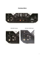
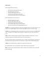
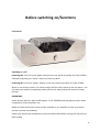
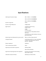
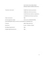
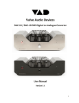
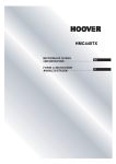
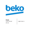
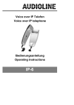
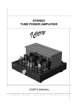
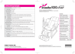
Valve Audio Devices DAC-‐10 / DAC-‐10 DSD Digital to Analogue Converter User Manual Version 3.5 1 Introduction The Valve Audio Devices DAC-‐10 / DAC-‐10 DSD valve DAC is an exquisitely engineered, hand-‐ built, point-‐to-‐point wired unit employing specifically selected components. It is designed for the audio purist and refined over countless hours to produce exceptional high definition sound with unparalleled musicality. Every component is selected with sound quality as the highest priority and its specially designed dual mono valve analogue stage, ultra-‐short signal path, native DSD direct playback and advanced dual mono 32bit PCM conversion stage provides the optimum environment for digital audio playback from a variety of signal sources. Our VAD DSD Playback platform is a purist design founded on a DSD direct filtered playback method without decimation and digital processing. When matched with similarly high quality components, the DAC-‐10 / DAC-‐10 DSD reproduce a truly natural sound with realism, emotion, micro-‐dynamics and resolution to satisfy the most discerning of audiophiles. Closing the gap to the original sound and delivering unparalleled musicality, with all of the original nuances, has now become closer than ever. The DAC-‐10 / DAC-‐10 DSD stands comparison with the world’s finest reference DACs – regardless of price -‐ and come with a 7-‐year Manufacturer Warranty. It has been designed and built with reliability in mind and will last a lifetime with appropriate care. Data Formats The DAC-‐10 / DAC-‐10 DSD will automatically recognise sample rates from 44 to 192kHz and bit rates of 16-‐24-‐32bit from SPDIF/AES3 digital audio compatible sources through: • COAXIAL, TOSlink, BNC and AES/EBU (AES/EBU DAC-‐10 only) • USB Audio 2.0 input dedicated for PCM audio files up to 32 bit/192kHz • USB Audio 2.0 input dedicated for DSD64 and DSD128datastream (DAC-‐10 DSD only). In the DAC-‐10 DSD, the second USB input replaces the AES/EBU SPDIF input of the DAC-‐10. 2 Technical information DSD64/DSD128 playback (DAC-‐10 DSD): Our dedicated DSD (Direct Stream Digital) playback platform passes the USB interfaced DSD Left and Right channel bitstream data through 1bit drivers and onto a high precision, double differential FIR (Finite Impulse Response) active filter. The signal is then passed through a passive analogue filter to retrieve the pure audio, which is then amplified by the vacuum tube triodes. Use of this technique provides the purest possible representation of the DSD stream as music. The analogue frequency response of our DSD playback is a staggering: 10Hz to 120 kHz with DSD128 and 10Hz to 100 kHz with DSD64 with a drop at 120kHz of only 3dB. DSD noise shaping technique frequencies are significantly higher than our 120kHz pass band. In addition, professionally distributed DSD recordings do not carry real information above the human audible spectrum, so there is no `ultrasonic energy` there to pass into your system. Therefore, we decided to open the analogue frequency response in our DSD playback trusting that music lovers will experience how much can be really perceived in the music reproduction. The S/N ratio of VAD DSD direct filtered playback is 110dB with DSD64 and 113dB with DSD128 Crucially, our DSD playback method is free of digital processing and separate from the PCM circuitry. SPDIF sources playback: SPDIF bi-‐phase signal is interfaced to a high frequency, high input impedance triode valve configured in balanced digital mode and precisely matched to our selected SPDIF receiver in balanced digital mode. This method gives the benefit of the DAC-‐10 / DAC-‐10 DSD being highly immune to the sometimes-‐poor electrical signal quality from SPDIF transports and/or digital coax interconnects, which can influence the sound. A better transport will improve the overall sound. However, the DAC-‐10 / DAC-‐10 DSD will sound exceptionally superior with even the most basic SPDIF signal sources and digital interconnects. PCM USB Audio playback: High-‐end asynchronous USB audio is I2S interfaced to the PCM 32bit decoding stage with two mono converters (L&R). The stage is free of any post filtering and coupled I/V to two mono vacuum tube triode analogue output stages. 3 Power supply: Power supplies are independent for digital and analogue and Left and Right channels. All power supplies are inductor (choke), loaded, series resistor-‐less and bespoke designed. The current generation of DAC-‐10 DSD has 18 power supplies working with five mains transformers. Vacuum tube analogue output stage: The DAC-‐10 / DAC-‐10 DSD vacuum tube triode analogue output stage is point to point engineered to operate as: 1. PCM stage differential audio signal coupling (transformer-‐less). 2. DSD stage audio signal coupling. 3. Gain control -‐ part of this function implemented in DC mode. 4. Signal dependent variable tube biasing (automatic). 5. Signal amplification. 6. SE and balanced out signal stage. The whole tube circuit is operating in pure Class A. Selected-‐by-‐VAD audio signal capacitors are hand wound waxed ALU foil paper in oil in parallel with silver mica and copper foil in Teflon to create our unique combination of one per output/channel. Casing: The unique VAD casing is designed as a monocoque structure with the fulfilled aim for extremely high mechanical rigidity, EMI and RFI screening and vibration damping. It is polymer coated and additionally polyurethane `silenced`. The only structural parts fitted with screws are the aluminium top cover and valve cover. Electrically the casing is directly fully grounded via the safety earth pin in fused IEC socket. Direct grounding provides the highest electrical safety and also means that the EMI/RFI screen really is a `screen`, not just a piece of metal in the way of interferences. 4 Used components: During long R&D process, all components were selected for the overall sound benefit of the whole design without compromises. The separate components count of the DAC-‐10 DSD is 600 and include: selected paper in oil and silver mica capacitors, 0.1% tolerance foil resistors, selection of Sanyo OsCon, Panasonic and Nichicon polymer caps, Rubycon ZLJ, ZLH, ZL, Panasonics FC, FM, FR, carbon resistors and metal resistors, silver wire and tinned copper wire, fast RF relays and old fashion solder tags, chosen top quality linear voltage regulators, Schottky rectifiers, FR diodes and valve rectifiers, inductors, ceramic valve bases, newest digital IC`s and NOS (New Old Stock) valves, non-‐ magnetic screws, copper rails, Teflon, silicone, selection of C0G,NPO,X7R,MKP,MKS capacitors and other parts including many VAD secrets. All components are new and current production (apart from NOS vacuum tubes), sourced mostly from UK suppliers. All designed and chosen by us for you to enjoy the music 5 CONTENTS Introduction 2 Technical info 3-‐5 Unpacking 6 Connection 7-‐8-‐9-‐10-‐11 Before Switching ON/functions 12-‐13-‐14 Safety 15-‐16 Burn in 17 Specifications 18-‐19 Warranty Information 20-‐21 Warranty registration form 22 Unpacking In the flight case you will find the following: • 1 x VAD DAC-‐10 / DAC-‐10 DSDvalve DAC • 1 x remote control • 1 x Power cord • 1 x Hex key (for removing the valve cover) • User manual Remove all contents. Keep the flight case in case of need to ship the DAC-‐10 / DAC-‐10 DSD. Place the DAC on a sturdy surface (e.g. hi-‐fi rack or isolation platform) and plug in the power. 6 Connection VAD DAC-‐10 inputs: VAD DAC-‐10 DSD inputs 7 Digital inputs DAC-‐10 digital audio connectivity: • AES/EBU balanced digital audio input • BNC SPDIF digital audio input • COAXIAL SPDIF digital audio input • TOSlink optical SPDIF digital audio input • USB 2.0 audio PCM input (up to 32bit/192kHz) DAC-‐10 DSD digital audio connectivity: • BNC SPDIF digital audio input • COAXIAL SPDIF digital audio input • TOSlink optical SPDIF digital audio input • USB 2.0 audio PCM input (up to 32bit/192kHz) • USB 2.0 audio DSD input for DSD64/DSD128 stream AES/EBU: Use a screened, twisted pair cable from the digital output of your CD transport or CD player to the AES/EBU digital input of the DAC-‐10(AES/EBU socket is a receptacle type) Coaxial: Use a RCA plug terminated, coaxial interconnect of your choice for the COAXIAL digital input. The cable for the COAXIAL input should be no longer than 1.5m (5 feet) for the best result USB: Use USB 2.0 cable fitted with USB type B plug terminated for the DAC side. For best results use a good quality USB 2.0 cable without any sleeve inductors. NB -‐ DAC-‐10 USB interfaces are powered from our on-‐board, purpose designed, extremely low noise linear power supply (not from your USB socket – which is used for data transfer only). TOSlink: Use preferably multi-‐strand glass fibre type optical audio cable. NB -‐ 24bit/192kHz sample rate playback through TOSlink cannot be guaranteed. BNC: Use same type of preferred coaxial cable as used for the RCA Coaxial input, terminated with the BNC plug. 8 Audio outputs: Balanced: Use screened, twisted pair cables fitted with 3pin XLR plugs (receptacle type plug for the DAC-‐10 / DAC-‐10 DSD end). When using the balanced connection, pin 1 is “ground”, pin 2 is “hot” and pin 3 “cold”. Make sure this complies with your other audio equipment and consult with your dealer for any necessary modifications. RCA:analogue interconnects for single ended outputs. RCA cables should ideally be no longer than 1.5m / 5 feet between the audio outputs of the DAC-‐10 / DAC-‐10 DSD and the line level input of your preamplifier or integrated amplifier. NB -‐ We advise that balanced and unbalanced audio outputs are not being connected/used simultaneously (possibility of ground loop on some systems). Input selector switches The VAD DAC-‐10 DSD has two rotary switches on the back panel: • Switch 1 (SW1) will let you choose between the TOSlink, BNC, Coaxial, PCM USB, DSD USB and DSD rate 64 or 128 • Switch 2 (SW2) provides three PCM decoding custom settings to choose: CD-‐Audio, Hi-‐ Res, Mix In COAX SW1 switch position DAC will automatically choose an active signal source between the AES/EBU and COAXIAL inputs. In DAC-‐10 -‐ DSD position is inactive DAC-‐10 DSDonly The AES/EBU SPDIF input is replaced by a USB DSD input for DSD64/DSD128 playback (example: dsf.dff. iso.). SW1 in DSD mode also activates a separate analogue `path` for DSD playback. 9 PCM and DSD Computer playback If you have both formats (PCM, DSD) of music files on your computer connect both USB inputs to your computer using quality USB 2.0 cables. Both USB interfaces will operate in kernel streaming (recommended) or ASIO mode selected at your software player end. To play DSD files: -‐ switch the DAC-‐10 SW1 switch to first DSD position (DSD64) or 2nd DSD position (DSD128) -‐ choose the DoPbitstreaming output format in the options of your computer software player To play PCM music files: -‐ stop the DSD playback -‐ switch the DAC-‐10 SW2 switch to PCM USB position -‐ choose the PCM compatible output format in options of your computer software player. Please note: your software won’t play native DSD into the USB PCM input or PCM into USB DSD input. -‐ If you listen to PCM only: there is no need to connect the second USB cable to DSD USB input -‐ If you listen to DSD only: there is no need to connect the second USB cable to PCM USB input. -‐ We recommend that the DAC gain control is turned down before selecting the DSD USB Audio format -‐ once the output of your software player is set to DSD, the gain can be increased as needed. DAC-‐10 / DAC-‐10 DSD USB Audio file formats: PCM music files: Any music file type supported by your computer audio software on Windows OS and Apple OS platforms -‐ up to 32bit/192kHz DSD64 anddouble rate DSD128music file types: Windows OS: DSF, DFF/DSDIFF (Developed and tested with JRiver MP18 -‐ DoP 1.0) DSD64 and double rate DSD128 Apple OS: DSF, DSDIFF, SACD ISO images (Developed and tested with Audirvana Plus). 10 Before switching on/functions Front Panel Switching on / off Powering ON: “Flip” the mains power switch on the rear panel of the DAC-‐10 / DAC-‐10 DSD followed by pushing the “Power” button on the front panel. Powering OFF: Press the “Power” button on the front panel of the DAC-‐10 / DAC-‐10 DSD. When in use at home, there is no need to switch OFF the main switch on the rear panel – use the back panel switch to completely power off the unit when leaving the house for longer periods. IMPORTANT: Power ON the DAC-‐10 / DAC-‐10 DSD approx. 2 min. BEFORE switching ON your other audio components such as amplifiers etc. Make sure that the Volume control of your amplifier or pre-‐amplifier is close to minimum position (volume turned down). Switch your other audio components such as amplifiers OFF before turning OFF the DAC-‐10 / DAC-‐10 DSD. 11 Whilst the DAC-‐10 / DAC-‐10 DSD will sound superb from the moment it is switched on, due to the nature of valves, its sound will improve even further as it warms up. After 20 minutes it will be on song, after approximately 40 minutes it will reach its peak performance. To maximise the life span of the valves, it is recommended to minimise the number of times that the unit is switched on and off -‐ e.g. where several listening session may be planned during the course of the day, it is better to turn the unit on before the first session and only turn it off at the end of the final session – rather than on and off at the end of each session. Ideally, the DAC-‐10 / DAC-‐10 DSD would be kept switched on. The DAC-‐10 / DAC-‐10 DSD have the power consumption of 58W during normal operation (with signal connected). Gain Control The remote-‐controlled signal output level (Gain) control is located in the centre of the front panel. Itis designed to match the output level of the DAC-‐10 / DAC-‐10 DSD to a wide range of preamplifiers and integrated amplifiers but can also facilitate direct connection to power amplifiers. In most circumstances, when used with a preamplifier or integrated amplifier, the output level of 2Vrms will be achieved atthe 12 o’clock position and pro audio level of 4.2Vrms at 3 o’clock (approximate). The remote control unit for the DAC-‐10 /DAC-‐10 DSD controls the gain control and allows up and down gain control from the listening position. Lock The Lock indicator will “light up” when the compatible digital signal is detected and the input of the DAC is synchronised with a digital signal source. The `Lock` indicator is only used for SPDIF input sources. The DAC is now ready to operate. DSD Rate switching The rotary selector switch (SW1) of the DAC-‐10 DSD serves also as a DSD rate switch. The nature of our DSD playback topology is direct filtered DSD playback without decimation and digital processing. VAD DSD playback is more analogue in its nature than digital, hence there is no DSD rate-‐sensing circuitry tapped into the stream. In this purist approach, the manual DSD rate switch is necessary. The first DSD position is for DSD64 and second (the last rotary position clockwise) for DSD128 12 You can notice the analogue nature of our VAD DSD platform -‐ simply by playing DSD64 in the DSD128 switch position, the playback will continue but with an analogue hiss as you would expect from an FM radio that is out of tune to the station. By using the correct filter for the correct DSD stream, accordingly, the hiss will disappear. 13 Safety Information Placement Apart from the valves, which, by their very nature, are designed to run hot, the DAC-‐10 / DAC-‐ 10 DSD is relatively cool running and operates well below the maximum allowed temperature for consumer audio. It should be positioned so as to allow free airflow around it and not placed on top of other equipment – particularly Class A amplifiers, which run hot. Possible vibrations should be minimised as far as possible. For example, the DAC-‐10 / DAC-‐10 DSD must not be placed on top of speakers. Ideally, the unit should be placed in line with (or slightly behind) the plane of your speakers and additional benefits may be gained by placing it on a good quality isolation platform. Cleaning the unit. Always disconnect the power cord from the mains socket when cleaning or performing other maintenance. Tube replacement. The front pair of matched valves can be replaced with the same type allowing users to tune the sound slightly. Please contact VAD or your dealer for advice on replacements. Valve codes 6SN7, 6N8S, 1578, ECC32, CV1988, 6SN7GT, 5692, CV181 or other direct equivalent to 6SN7 are compatible.Please note: The protective cover will not fit over the taller CV181 valves. Use of any other valve type will damage the circuit and invalidate the warranty. In case of “valve rolling”, the use of octal valve socket savers is strongly advisable, as any damage to the valve sockets caused by “valve rolling” is not covered by the warranty. The matched pair of 6N6P should only be replaced with the same type or: The matched pair of 6N6P (middle pair) should only be replaced with the same type or: 6H30, 6N30P, E88CC, 6DJ8 The pair of CV574 rectifier (back pair) valves can be replaced with the same type or 6C5S, EZ35 or 6X5GT equivalents. Only a VAD authorised service agent should replace the internal ECC84 HF valve. 14 IMPORTANT: Tube (valve) replacement The DAC must be powered OFF by the mains switch on the back panel (mains IEC socket) and then fully disconnected from the mains socket for a minimum of10 minutes before commencing any tube replacement. (`bleeding` circuit fully discharges power supplies within 2 minutes, but take care as the valves may be still too hot to handle). Fuse The unit is fitted with an Anti Surge 1A fuse, which is located in the IEC mains socket on the back panel – this must be replaced only with the same amperage value! (a spare fuse is provided in the fuse “drawer”). In case of subsequent fuse failure, the unit should to be sent to an authorised VAD service agent for checking. Earth connection Theunit must be earthed! This is provided by the safety earth contact in the IEC mains socket. Make sure that the earth connection of your home mains electrical installation is in order. Removing the protective Valve Cover. The valve cover is secured to the top of the unit by way of 4 hex bolts being accessible through slots in the valve cover. The cover may be removed in order to facilitate tube replacement by using the supplied long hex key (2mm) tool to undo the bolts. We do not recommend using DAC-‐10 / DAC-‐10 DSD without the protective cover – valves are hot when operating. DAC-‐10 / DAC-‐10 DSD valvesoperational `life span` information. The DAC-‐10 / DAC-‐10 DSD have been designed to the highest parameters, with each component rigorously tested. We have chosen to use NOS (New Old Stock) valves due to their audio qualities and longevity. However, due to the nature of vacuum valves, we offer a 90 days from purchase date warranty for the valves originally supplied for peace of mind. 15 `Burn-‐in` time. Each DAC-‐10 / DAC-‐10 DSD is hand-‐built and then tested through for a minimum of 24 hours `burn-‐in` test (all input sources, all output levels). This means that the DAC-‐10 / DAC-‐10 DSD has a 24 hours burn-‐in period prior to delivery. Once installed, we recommend a further 100 hours burn-‐in period for the DAC-‐10 / DAC-‐10 DSD to reach its full potential. 16 Specifications Audio Signal Frequency Range: 10Hz -‐ 20 kHz +/-‐ 0.1dB (PCM) 10Hz to 120 kHz/-‐3dB (DSD128) 10Hz to 100 kHz/-‐3dB (DSD64) Dynamic range PCM 120dB Dynamic range DSD64/128 110dB/113dB Digital inputs: 1x AES/EBU (DAC-‐10 only) 1x RCA Coaxial 1x BNC 1x Toslink optical 1x asynchronous 32 bit/192kHz USB 2.0 PCM input 1x asynchronous USB 2.0 DSD DoP 1.0 input (DAC-‐10 DSD only) Output Signal Level (adjustable via gain control): 50mV to 4.4Vrms (approximate) Analogue Outputs: Output impedance: 1x XLR (balanced) max. 4.5Vrms-‐ adjustable 1 xSingle ended RCA outputs 50mV to 4.4Vrms – adjustable <300ohms Total correlated jitter (SPDIF): <30ps Digital input word widths supported 16-‐24bit (SPDIF) 16-‐24-‐32bit (USB PCM) Digital input sampling frequencies supported: All sample rates between and including 44kHz-‐192kHz (PCM) USB Audio 2.0:(DAC-‐10 PCM): 16-‐32bit/up to 192 kHz PCM 17 (DAC-‐10 DSD): PCM, DSD64/2.8MHz DSD128/5.64MHz-‐6.144MHz (double rate) Thermionic valves used: 2x 6SN7 dual triode (or equivalent) 2x 6N6P dual triode (or equivalent) 2x CV574 full wave rectifier (or equivalent) 1x ECC84 HF dual triode (or equivalent) Power consumption: 58W AC mains operation voltage: Factory set for 220-‐240V/50/60Hz (100-‐120V/50/60Hz factory set version can be ordered at no additional cost) Fuse type: 1A Anti Surge 20mm fuse Dimensions: H 15cm x W 44cm x D 29cm Net Weight (approximate): 14kg Shipping weight (approximate) 19kg 18 Valve Audio Devices (VAD) DAC-‐10 / DAC-‐10 DSD Warranty Information Valve Audio Devices Limited warrants this product to be free from defects in materials and workmanship for a period of seven (7) years from the date of purchase (subjectto the terms set forth below). Valve Audio Devices will repair or replace (at VAD option) thisproduct or any defective parts in this product within the warranty period. Warranty periods may vary from country to country. If in doubt, consult your dealer and ensure that you retain proof of purchase.To obtain warranty service, please contact the VAD authorized dealer from which youpurchased this product. If your dealer is not equipped to perform the repair of your VAD product, it may be returned by you or your dealer to Valve Audio Devices or an alternative authorized VAD serviceagent.You will need to ship this product in either its original packaging or packaging affording an equaldegree of protection. To qualify for the full seven year warranty, the customer must return the Warranty Registration Form (included as the last page of this manual) to Valve Audio Devices Limited within 30 days of purchase. Proof of purchase in the form of a bill of sale or receipted invoice, which acts as evidence that this product iswithin the warranty period, must be presented to obtain under-‐warranty service. This Warranty is invalid if the factory-‐applied serial number and/or Warranty sticker has been altered or removed from this product. This Warranty is invalid if the proof of purchase cannot be presented. A returned product must be accompanied by a written description of the defect. Any changes or modifications to the product (apart from replacing the tubes as directed in the user manual) will invalidate the 7 year warranty This Warranty does not cover cosmetic damage or damage due to acts of God, accident, misuse, abuse,negligence, commercial use, or modification of, or to any part of, the product. This Warranty does notcover damage due to improper operation, maintenance or installation, or attempted repair by anyoneother than Valve Audio Devices or a VAD dealer, or authorized service agent, which is authorized to carry outValve Audio Devices warranty work. Any unauthorized repairs will void this Warranty. This Warrantydoes not cover products sold AS IS or WITH ALL FAULTS. 19 REPAIRS OR REPLACEMENTS AS PROVIDED UNDER THIS WARRANTY ARE THE EXCLUSIVE REMEDY OFTHE CONSUMER. VALVE AUDIO DEVICES LIMITED (VAD) SHALL NOT BE LIABLE FOR ANY INCIDENTAL OR CONSEQUENTIALDAMAGES FOR BREACH OF ANY EXPRESS OR IMPLIED WARRANTY IN THIS PRODUCT. EXCEPT TO THE EXTENT PROHIBITED BY LAW, THIS WARRANTY IS EXCLUSIVE AND IN LIEU OF ALL OTHER EXPRESS AND IMPLIED WARRANTIES WHATSOEVER INCLUDING, BUT NOT LIMITED TO, THE WARRANTY OF MERCHANTABILITY AND FITNESS FOR A PRACTICAL PURPOSE. Some Countries and US states do not allow the exclusion or limitation of incidental or consequentialdamages or implied warranties so the above exclusions may not apply to you. This Warranty gives youspecific legal rights, and you may have other statutory rights, which vary from state to state or country tocountry. For any service, in or out of warranty, please contact your dealer. Valve Audio Devices reserves the right to modify the design of any product without obligation to purchasers of previously manufactured products and to change the prices or specifications of any product without notice or obligation to any person. DAC-‐10 /DAC-‐10 DSD is a UK Patent Office international registered design. Valve Audio Devices Limited 17 Ashby Road Welton DAVENTRY NORTHAMPTONSHIRE NN11 2JS UNITED KINGDOM Company No. 08298028 Copyright Valve Audio Devices Limited 2013 20 Valve Audio Devices (VAD) Warranty Registration Form First Name: Title Last Name: Full address (number and street): City: Postcode/Zipcode: State/Province: Country: Phone Number: E-mail Address (receive up-to-date information on new products and promotions): Date of Purchase (day/month/year): Please indicate the serial number and warranty number of this product. (Found on the ID labels attached to your product). S/N No………………………. Warranty No……………….................... You may receive information on a new products and special promotions. Email or call us to update your communication preferences. We will not share any of your information with other companies for any marketing purposes If you do not wish us to send you VAD product updates, please mark this box Please complete the form upon purchasing your product. Detach and send it within 30days to: Valve Audio Devices Limited, 17 Ashby Road, Welton, Daventry, Northamptonshire.NN11 2JS 21