1
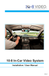
PATROL PC 344 John Dietsch Blvd., Unit 1 & 2 North Attleboro, MA 02763 www.patrolpc.com 508.699.0458 RT-12i USER MANUAL 1|Page Thank You Thank you for purchasing the Patrol PC RT-12i Ultra-Rugged Tablet. Proudly designed and manufactured in the USA for use in Police, Fire, and EMS vehicles, your product was built to perform under a wide range of punishing field operating conditions. We expect it will deliver years of reliable service to you. Should you have any questions about our product, we welcome your inquiries and calls at: Patrol PC 344 John L. Dietsch Blvd., Units 1&2 North Attleboro, MA 02763 508.699.0249 www.patrolpc.com 2|Page TABLE OF CONTENTS Product Warranty..................................................................................................................................... 4 Customer Service ...................................................................................................................................... 5 Power Requirements................................................................................................................................. 7 Notice for Units Equipped With Fans..................................................................................................... 8 Control Line Option.................................................................................................................................. 9 Mounting Options..................................................................................................................................... 10 Typical Install............................................................................................................................................ 11 Using Your Own Windows Images.......................................................................................................... 13 Overview of RT-12i Bezel Buttons........................................................................................................... 14 Rear Panel Connections............................................................................................................................ 15 Using the RTi Control Panel.................................................................................................................... 16 "Main Setup" Tab.............................................................................................................................. 17 "LCD Brightness" Tab...................................................................................................................... 19 "Vehicle Control" Tab....................................................................................................................... 21 "Speed Buttons" Tab.......................................................................................................................... 24 "Hot Keys" Tab.................................................................................................................................. 27 "Power" Tab...................................................................................................................................... 29 "System Info" Tab.............................................................................................................................. 31 Options........................................................................................................................................................ 33 Barcode Reader......................................................................................................................................... 34 Hard Drive Access - No Internal Antennas............................................................................................. 37 Hard Drive Access - Internal Antennas.................................................................................................. 39 Certified Solid State Hard Drive.............................................................................................................. 41 Troubleshooting........................................................................................................................................ 42 3|Page Product Warranty PatrolPC A division of Advanced Electronic Design, Inc. 344 John Dietsch Blvd., Unit 1 & 2 North Attleboro, MA 02763 Phone: 508-699-0458 FAX: 508-699-2531 http://www.patrolpc.com 3 Year Limited Warranty Advanced Electronic Design (AED) warrants all factory configured tablet computers and related factory installed or approved accessories for 3 (three) years against defects in material, workmanship or design commencing on date of shipment to the Customer. AED will repair or replace or, at AED’s option, refund the purchase price for any product deemed defective upon examination by AED. This warranty does not cover products that have been subjected to intentional misuse; abuse; neglect; improper operation; inadequate maintenance; repair or alteration of the product; or unusual deterioration or damage to the product due to the environment where the product is used, including accidental damage to the product in the course of normal, recommended use. Customer installed software is not covered under this warranty. This warranty shall apply if; (1) the products shall, between the date of shipment and date for first use, be stored and maintained in “as shipped” condition; (2) the products shall be installed, used and maintained according to AED’s instructions and guidelines, if any, and (3) no modification to the products shall be made after shipment without prior and written authorization from AED. Limitations of Use AED PRODUCTS ARE NOT AUTHORIZED FOR USE AS MISSION-CRITICAL COMPONENTS IN LIFESUPPORT, HAZARDOUS ENVIRONMENTS, NUCLEAR, AIRCRAFT, OR SIMILAR APPLICATIONS WITHOUT THE SPECIFIC PRIOR WRITTEN APPROVAL OF THE PRESIDENT OF AED. CUSTOMER SHALL ASSUME ALL LIABILITY IN SUCH APPLICATIONS. Limitations of Liability UNDER NO CIRCUMSTANCES WILL AED BE LIABLE FOR AN INCIDENTAL OR CONSEQUENTIAL DAMAGES, OR FOR ANY OTHER LOSS, DAMAGE OF EXPENSE OF ANY KIND, INCLUDING LOSS OF PROFITS, ARISING IN CONNECTION WITH THE USE OF OR INABILITY TO USE AED’S PRODUCTS FURNISHED UNDER THIS CONTRACT. AED’S MAXIMUM LIABILITY SHALL NOT EXCEED AND CUSTOMER’S REMEDY IS LIMITED TO EITHER (1) REPAIR OF REPLACEMENT OF THE DEFECTIVE PART OF PRODUCT, OR (2) AT AED’S OPTION, RETURN OF THE PRODUCT AND REFUND OF THE PURCHASE PRICE; AND SUCH REMEDY SHALL BE CUSTOMER’S ENTIRE AND EXCLUSIVE REMEDY. Returning Product to AED AED Customer Service must be contacted prior to returning any product to obtain a Return Material Authorization (RMA) Number to assure receipt and proper handling. Any order returned to AED without an approval RMA Number will not be accepted and will be returned to Customer at Customer’s expense. RMA number must be marked on the container. The unit must be boxed in secure packaging to avoid damage in transit. EXCEPT AS PROVIDED HEREIN, AED EXPRESSLY EXCLUDES AND DISCLAIMS ALL WARRANTIES, EXPRESSED OR IMPLIED INCLUDING, WITHOUT LIMITATION, ANY IMPLIED WARRANTY OF MERCHANTABILITY OR FITNESS FOR A PARTICULAR PURPOSE; AND HE WARRANTY WHICH FOLLWS IN LIEU OF ANY AND ALL OTHER OBLIGATIONS OR LIABILITY ON AED’S PART. Thank You For Buying PatrolPC 4|Page Using The Patrol PC Ticket System If a problem occurs with your RT-12i tablet, creating a support ticket is the quickest and most efficient way to get the problem resolved quickly. You can create a support ticket on our website at http://www.patrolpc.com/support/login. After creating the ticket, our support staff will call you or email you back swiftly to get the problem resolved. During our office hours (Monday to Friday, 9AM-5PM ET), we will get back to you on the same day. To Create a Support Account: 1. Go to http://www.patrolpc.com/support/login. 2. Click "Create Account". You should now be at a screen similar to the one below. 3. Fill in all fields. Pick a username and password and store the information is a safe place for future reference. Please ensure that your email address is correct so that we can notify you of any issues via email. 4. When all fields have been completed, click "Register". To Login to Your Account: 1. Go to http://www.patrolpc.com/support/login. 2. Type in your username and password, then click "Login". To Create a Ticket: 1. Go to http://www.patrolpc.com/support/login. 5|Page 2. Type in your username and password, then click "Login". 3. Click on the "Add" button in the "Tickets" box. You should now be at a screen similar to the one below. 4. Fill in all fields. Describe the issue you are experiencing in the "Description" field. If possible, please mention which model is experiencing the problem, the serial number, what version of Windows it is running, and the version of your RTi Control Panel Software. If you have a screenshot or picture or text file that may help diagnose the issue, you may attach it in the "Attach File" field. Just click "Choose File", then navigate to and select the file you wish to attach to the support ticket. 5. When you are finished with all the fields, verify your phone number, then click "Add". 6|Page Power Requirements This product is designed to run on 11-15 Volts DC (3 Amps typical, 7 Amps max). NOTICE TO INSTALLERS When installing the RT-12i in a vehicle: Connect the power cable to an ALWAYS-ON 12 Volt line that is connected directly to the vehicle battery. DO NOT connect the power cable to a 12 Volt line that is shut off when the vehicle key is removed. DO NOT connect the power cable to a charge-guard or equivalent device. DO NOT connect the power cable to a power converter. 7|Page Notice For Units Equipped With Fans If your unit is equipped with a fan, ensure that it is installed in a location where there is sufficient clearance for air to flow into the fan on the back of the case and out of the air outlet on the top of the computer. 8|Page Control Line Option If this option is installed, your RT-12i will have a connector which can interrupt a control line when the computer is shut off. This is useful if you would like to trigger a power up/down of other devices with a control line at the same time as the computer. Units with this option installed will come with a control line cable as shown below: The black wire will connect to the control line voltage source (usually a +12V DC un-switched line), and the red wire will connect to the control line of the device you wish to control. When the computer is shut down, the control line is interrupted and the voltage does not continue to the red wire. When the computer is running, the red wire will be carrying the control line voltage. Power Specifications: The control line voltage must be within 8-28 Volts DC. The maximum current is 1.8 Amps. Installing the Control Line Cable: 1. Solder your control line wires to the RT-12i Control Line Cable following the example below: 2. Connect the RT-12i Control Line Cable to the RT-12i at the location shown below: 9|Page Mounting Options - Patrol PC tablets are designed to be easily deployed in any marked and unmarked patrol vehicle, using a wide variety of vehicle mounting hardware options from HiNT Peripherals, Havis, Gamer-Johnson, Jotto Desk, and Ram Mounting Systems. - Due to our clean all-in-one tablet design, a typical Patrol PC install will take up less cockpit space, will be more ergonomically friendly and easier to use, will use less mounting hardware and require less installation labor, saving you both time and money as compared to other multi-piece or docked solutions. - To mount our tablet, all you need is four screws and a mounting bracket with the following hole spacing: 10 | P a g e Typical Install Car installs vary greatly between each car make and model. A general guideline for a typical car install is provided below. 1. Locate a 12 Volt (DC) always-on power cable. NOTE: DO NOT install a charge guard or equivalent device between the computer and the 12 Volt always-on line. DO NOT use the lighter adapter power, since this line is switched on or off with the ignition. 2. Disconnect the positive power cable from the car battery. 3. Splice the supplied power cable (with 10 amp fuse) with the always-on power cable. Connect the ground wire to a solid ground point. 4. Re-connect the positive battery terminal. With a multi-meter, check the connector of the RT-12i power cable for 12 Volts DC and ensure that there are no shorts between the positive cable and ground. 5. Install the computer mount per manufacturer instructions. 6. Plug in the power cable and all USB cables/peripherals, then secure the wires with the tie wraps. Leave service loops to avoid straining the plugs. 11 | P a g e 7. Turn on the RT-12i to check functionality. If it boots successfully, shut down computer, then secure the rear connector cover by screwing in the screws circled below. 8. Mount the tablet and keyboard (if required) to the computer mount per manufacturer instructions. Adjust the computer and keyboard position as needed. 12 | P a g e Using Your Own Windows Images - Patrol PC recommends that you use the stock hard drive image provided for best performance. - If you wish to perform a new Windows installation, the drivers and the RTi Control Panel must be installed manually. Installing the RT-12i Drivers After a fresh Windows install, download the latest drivers from our website at www.patrolpc.com/ppcsupport/downloads, then install them in the following order: 1. Chipset 2. Graphics 3. LAN Wired 4. LAN Wireless (if the unit has this option) 5. Touchscreen 6. Audio 7. GPS (if the unit has this option) 8. Barcode Reader (if the unit has this option) 9. Fingerprint Scanner (if the unit has this option) 10. Intel Management (optional) 11. HD Solid State (for units with solid state hard drives, optional) Installing the RTi Control Panel 1. Go to our website and download the latest RTi Control Panel at www.patrolpc.com/ppc-support/downloads. 2. Double-click the downloaded file to install the RTi Control Panel. 3. Choose the "Typical Installation". 4. When the installation is complete, you may be prompted to update the BIOS or Embedded Controller. Allow it to update. - After the update is complete, the computer will shut down. The screen will flash, then fade to black. This is normal during a BIOS or Embedded Controller update. - After the screen fades to black, you can start the computer again. It will not fully boot the first few times. Keep on turning the computer back on until it boots into Windows. Once it boots into Windows, you will be all set. 13 | P a g e Overview of the RT-12i Bezel The RT-12i bezel has a row of touch-sensitive buttons and one physical power button. There are also 4 status LEDs, including hard disk and network activity LEDs, which can be turned off if desired. The assignable buttons (1,2,3,4) are a convenient way to launch applications or perform other tasks. Normal Orientation Bezel 1 2 3 4 3 2 5 6 2 3 4 3 2 5 6 Port-scape Orientation Bezel 1 1. Brightness Slider: Slide your finger across this area to increase or decrease screen brightness. You may also touch the slider at any point to quickly set the brightness to the corresponding value. 2. Assignable Buttons 1-4: Buttons can be assigned to various functions (see "Hot Keys Tab" section). 3. Status LED's: Different LED's light when there is any hard disk, wired network, or wireless network activity, as well as other functions (see "LCD Brightness Tab" section). 4. Power Button: Press this button to turn on the computer. This can also be used as the sleep or hibernate button while in Windows. 5. Volume Slider: Slide your finger across this area to increase or decrease speaker volume. You may also touch the slider at any point to quickly set the volume to the corresponding value. 6. Ambient Light Sensor: Detects the amount of ambient light when the screen is in Auto Bright mode (see "LCD Brightness Tab" section). 14 | P a g e Rear Panel Connections NOTE: Some ports are optional and may not be installed in all units. 1. Power Connector - Connect the power cable here. 2. Ethernet Ports - Gigabit Ethernet Ports. 3. Display Port - Display port video output. 4. USB Ports - USB 2.0 ports. 5. Micro HDMI Port - Micro HDMI video output. 6. Microphone In Jack - 1/8" Microphone Input. 7. Headphone Out Jack - 1/8" Headphone Output. 15 | P a g e Control Panel Overview The RTi Control Panel is a great tool to customize your RT-12i computer to your personal preferences. Speed Buttons: Assignable shortcuts to various programs. Speakers: Volume sliders, buttons, and mute function. Power: Turn off, hibernate, or put your computer to sleep. LCD Off: Turns off the LCD backlighting until the touch screen, brightness slider, volume slider, mouse, or track pad is touched. More Info: Information on the computer battery if it is installed. Minimize: Minimize the RTi control panel window. Setup: Change various computer settings. 16 | P a g e Main Setup Tab The Main Setup tab has an assortment of top-level control panel settings. You can create a password to get into the settings. You can also change which buttons are available in the RTi Control Panel window. See below for more details. User Setup Access Only Admin can modify settings - If check-marked, only a Windows account with Administrator credentials can view or change the RTi Control Panel Settings. Password Section - If a password is desired to view and make changes to the RTi Control Panel settings, type the desired password in both fields, then press "Set Password". The next time you try to enter the Computer Setup page, it will require a password to view and make changes to the RTi Control Panel settings. To remove the password, just click "Delete Password". Application Control Hide from Taskbar - If check-marked, the RTi Control Panel program will not show up on the Windows 17 | P a g e Taskbar. Display Icon in Status Bar - If check-marked, an icon for the RTi control panel will be present in the Windows status bar. Show Battery Life in Task Bar - If check-marked and if a battery is installed, a battery life meter will be present in the Windows task bar. Power Control Buttons Sleep - If check-marked, a button will be present in the RTi Control Panel window to put the computer into sleep mode. Hibernate - If check-marked, a button will be present in the RTi Control Panel window to put the computer into hibernate mode. Shutdown - If check-marked, a button will be present in the RTi Control Panel window to shut down the computer. Ask for Confirmation - If check-marked, a confirmation message will appear when trying to press the Sleep, Hibernate, or Shutdown buttons in the RTi Control Panel window. Windows Setup Control Touchscreen Setup - A shortcut to the touch screen settings and calibration software. Use this link if your touch screen is not responding to your touch accurately. Power Control Panel - A shortcut to the Windows power options. 18 | P a g e LCD Brightness Tab The LCD Brightness tab contains settings that alter the brightness of the LCD screen, including the Auto Bright function. You can also change the settings of the status LEDs. Bezel LED Setup Power On - When check-marked, the status LED will blink once when the computer is starting up. Sleeping - When check-marked, the status LED will blink slowly when the computer is in a sleep state. Charging - When check-marked, the status LED will blink slowly if the battery is being charged (if installed). Delayed Shutdown Pending - When check-marked, status LED will blink if an Auto Off Shutdown in pending. Critical Shutdown Pending - When check-marked, Status LED will blink if a Critical Shutdown is pending. 19 | P a g e Computer Blanking Show Main Button For Blanking - When check-marked, an "LCD Off" button will be present in the RTi Control Panel Window. This button will turn off the LCD backlight until the screen or the brightness slider is touched. Mute Speakers When Blanking - When check-marked, all audio will be muted when the LCD backlight is turned off (blanked). Startup Brightness Slider - This determines the brightness of the screen when the computer starts up. Start in Auto Bright - This over-rides the Startup Brightness slider and sets computer to start up in Auto Bright mode. Disable Bright Slider - This will disable the bezel brightness slider. When check-marked, the bezel brightness slider is not responsive to touch. NOTE: The Auto Bright function, or Automatic LCD Brightness, uses a built-in light sensor to dynamically change the brightness of the screen depending on the computer's surroundings. It is optional, so if your unit does not have the ambient light sensor installed, the buttons pertaining to the Auto Bright function will be grayed out. Automatic LCD Brightness Adjust Speed - Adjusts the speed at which the brightness of the screen changes when the amount of ambient light changes. Enable/Disable - Turn Auto Bright On or Off. Set Defaults - Set the Default Adjust Speed and Brightness Graph. Disable Brightness Slider in Automatic Mode - Disables the bezel brightness slider when the computer is in Automatic LCD Brightness mode. NOTE: It is generally recommended to keep the adjust speed slow since a rapidly changing brightness can be distracting. For instance, if a car drives into the shade for a second, it is better to "ignore" that quick change in ambient light by using a slow adjust speed. Graph - This graph plots the Screen Brightness versus the Ambient light level. It allows for fine tuning of the brightness of the screen for different ambient light levels. When hovering the mouse pointer over the graph, two points will appear which can be moved. Use these points to adjust the graph as desired. 20 | P a g e Vehicle Control Tab In Vehicle Control tab, you can change how the computer acts to changes in system voltage (when installed in a vehicle, the voltage from the battery). You can set the computer to turn on automatically when the vehicle is started. You can specify the voltage at which the computer automatically shuts down, with a delay if desired. You can also set a critical battery voltage at which the computer will shut down immediately to prevent excessive draining or damage to the battery. Auto Computer On Turn on computer when vehicle is started - When check-marked, the computer will automatically turn on when the system voltage reaches the specified value in the "Auto On/Off Threshold" field. Auto Computer Off Turn off computer when vehicle is off - If check-marked, the computer will automatically shut down, go to 21 | P a g e sleep, or hibernate when the system voltage reaches the specified value in the "Auto On/Off Threshold" field. Allow user to cancel auto shutdown - If check-marked, a button will be present to cancel the auto computer off timer. Canceling the timer would avoid an auto-off shutdown, sleep, or hibernate. NOTE: This does not apply to the Vehicle Battery Protector Shutdown. Shutdown Delay - If "Auto Computer Off" is enabled, this will set the delay time for shutdown, sleep, or hibernate after the auto off threshold has been reached. The format is "HOURS:MINUTES". Setting it to 0:00 will produce a 30 second delay. Vehicle Battery Protector Shutdown Shutdown immediately at critical battery voltage - If check-marked, the computer will initiate a shutdown approximately 1 minute after the system voltage goes below the value set in the "Voltage" field. NOTE: If the computer is in sleep mode when this threshold is met, it will wake up the computer and then initiate a shutdown in approximately 1 minute. Auto On/Off Threshold The voltage at which the "Auto Computer On" and "Auto Computer Off" functions operate. The "Shutdown", "Sleep", and "Hibernate" options set what the computer will do when the threshold is met. Shutdown - If the system voltage goes below the threshold, the computer will initiate a shutdown. If the system voltage goes above the threshold, the computer will turn on. Sleep - If the system voltage goes below the threshold, the computer will go to sleep. If the system voltage goes above the threshold once the computer is in sleep mode, it will not attempt to wake up the computer. Pressing the power button, a button on the keyboard, or a mouse click will wake the computer. If the system voltage goes above the threshold while the computer is off, it will turn on the computer. NOTE: If you wake up the computer once sleep mode was initiated, the RTi Control Panel will assume that you wish to continue working on the computer. The sleep timer will not be initiated again until the voltage threshold is crossed again or the computer is restarted. Hibernate - If the system voltage goes below the threshold, the computer will enter hibernate mode. If the system voltage goes above the threshold once the computer is in hibernate mode, it will resume Windows. If the system voltage goes above the threshold while the computer is off, it will turn on the computer. NOTE: If you resume the computer once hibernate mode was initiated, the RTi Control Panel will assume that you wish to continue working on the computer. The hibernate timer will not be initiated again until the voltage threshold is crossed again or the computer is restarted. 22 | P a g e Setting the Auto On/Off Threshold The Auto On/Off function works by constantly measuring the system voltage (when installed in a vehicle, this is the battery voltage). With an On/Off threshold voltage set, the computer will turn on when the voltage goes over the threshold and shut down, sleep, or hibernate when the voltage goes under the threshold. The "Shutdown Delay" sets how long the computer waits after the threshold is met to shut down, sleep, or hibernate. The "Vehicle Battery Protector Shutdown" will shut down the computer within a minute after reaching the critical voltage threshold. The following procedure serves as a guide to help you find the correct threshold values. Safety First: Perform the following steps in a safe location clear of any traffic. Ensure the vehicle is in Park and that no one is in front of or behind the vehicle. 1. With the engine running, navigate to the "Vehicle Control" tab. 2. Note the average system voltage with the engine running. 3. Turn off the engine then wait 5 minutes. 4. Note the average system voltage with the engine off. 5. Set the "Auto On/Off threshold" to a voltage in-between the engine-on voltage and the engine-off voltage (a good starting point is 1 to 2 volts above the engine-off voltage). Set what function you wish to occur when the threshold is met (Shutdown, Sleep, Hibernate). NOTE: This voltage setting may require fine tuning to get the results you want. If you leave the car off overnight, and during that time, the computer turns back on unexpectedly, your Auto On/Off threshold may be set too low. If your shut down timer starts when the car turns on, the Auto On/Off threshold may be set too high. 6. If you wish to set the critical battery voltage, ensure "Shutdown immediately at critical battery voltage" is check-marked. Set the voltage to the lowest level you would want the battery voltage to go (10.5 volts is usually a good setting for most vehicles). 7. Click "Apply" after all settings are as desired. NOTE: The Auto Off and Auto On functions work fine independently as well. For example, if you just want to use the Auto Computer Off feature, you can check-mark only that feature and set the related settings. Voltage Graph This graph contains a short history of the system voltage. The graph is showing system voltage over time. The large bold number at the bottom is the current system voltage. The "Minimum Voltage" registers the lowest voltage recorded when the voltage dips. 23 | P a g e Speed Buttons Tab The Speed Buttons tab allows you to set up which speed buttons will be available in the RTi Control Panel window and what the buttons will launch. Categories The field on the left contains Categories of Speed Buttons. Each category can contain 6 speed buttons (set in the "Buttons" field). Add - Add a new speed button category. Rename - Select a category and the click "Rename" to rename that category. Delete - Select a category and then click "Delete" to delete that category. 24 | P a g e Set Home Buttons - Select a category, then click "Set Home Buttons". The selected category will be present in the RTi Control Panel Window. Adding a Speed Button 1. Select the category in which you want to create a new Speed Button. 2. Pick a blank (or already used) button in the "Buttons Field" and click "Edit" to the right of it. 3. You will see the "Button Editor" window. 4. Type the desired name of the speed button into the "Name" field. If you want this button to be hidden, check-mark "Hide this button". 5. Select which icon you wish to be displayed on the button: No Icon - Only the name will be displayed on the speed button in text. 25 | P a g e Use Launch File Icon - The default icon of the application will be displayed on the speed button. Custom Icon - Pick a custom icon to be displayed on the speed button. Click "Browse" and navigate to the desired icon. Click "Remove" if you no longer want to use that icon for the speed button. 6. If you want the speed button to launch an application, go to 6A. If you want it to take you to another speed button category, go to 6B. 6A. In the "Launcher" field, click "Browse" to navigate to and select the application you want to link to this button. Click "Remove" if you no longer want this application to be linked to the speed button. 6B. You can make this speed button link to another speed button category by selecting the category in the "Speed Button Set" field. Clicking "Remove" will remove this link. 7. If you want the speed button to turn on Auto Bright mode when pressed, select the "Enable Ambient Light" option. Otherwise, leave "None" selected. 8. Click "Save" in the button editor, then click "Apply" in the "Computer Setup" window. Click Yes to confirm. 26 | P a g e Hot Keys Tab In the Hot Keys tab, you can assign various functions to the bezel buttons (1-4) and to various keyboard keys (for example, CTRL & F2 can Blank the LCD screen). Function Details Shutdown - Shuts down the computer when the Hot Key is pressed. Hibernate - Puts the computer in hibernate mode when the Hot Key is pressed. Sleep - Puts the computer in sleep mode when the Hot Key is pressed. Logoff - Logs off the current user account when the Hot Key is pressed. Launch - Launches an application. Once selected, the "Browse" field will be available. Click "Browse" and browse to the desired application. Brightness - You can choose to "Increment", "Decrement", or "Set Value" to a specific Brightness (Low is 1, High is 100). When Increment or Decrement is selected, you can also choose by what amount you wish to increment or decrement the brightness by typing it in the field that appears. 27 | P a g e Main Volume - If you select "On", the Hot Key will un-mute the audio. If you select "Off" the Hot Key will mute the audio. Selecting "Toggle" will mute the audio when the Hot Key is first pressed, then un-mute the audio when it is pressed again and repeat. You can choose to "Increment", "Decrement", or "Set Value" to a specific Volume (Low is 1, High is 100). When Increment or Decrement is selected, you can also choose by what amount you wish to increment or decrement the brightness by typing it in the field that appears. Blanking - If you select "On", the Hot Key will turn on blanking, which means the LCD backlight will be turned off. If you select "Off", the Hot Key will turn off blanking, turning the LCD backlight back on. "Toggle" will turn blanking on and off with each consecutive Hot Key press. Ambient Light Control - If you select "On", the Hot Key will turn on the Auto Bright function. If you select "Off", the Hot Key will turn off the Auto Bright function. "Toggle" will turn the Auto Bright function on and off with each consecutive Hot Key press. Barcode Trigger - Triggers the internal barcode reader (if option is installed) to begin scanning. Show Hotkey Message - When check-marked, a pop-up message will appear when any assigned hotkey is pressed, letting you know which hotkey was pressed. How to set a Hot Key 1. Select which bezel button or key combination your want to initiate the hot key. NOTE: If you want the hot key to be a keyboard key, select the "Key" Radio Button, then click inside the key field. Press the key or key combination that you want to assign (for example, CTRL F2). 2. Select which function you want to be assigned to the Hot Key (for example, "Main Volume"). If needed, select and set the function detail (for example, "Increment" by "30"). 3. Click "Add Hot Key". The Hot Key will appear in the field to the left. If you would like an on-screen message to appear each time the Hot Key is pressed, check-mark "Show Hotkey Message". 28 | P a g e Power Tab NOTE: The Fan Settings will only make a difference if the Fan option is installed in your unit. If your unit does not have a fan installed, select "Disabled" under "Fan Control". Fan Control Disabled - When check-marked, the internal fan will be disabled. 2-Speed - When check-marked, the fan will only have two speeds, low and high. These speeds will be triggered according to the temperatures set in the "Fan Setting" field. Variable - When check-marked, the fan will gradually increase speed based on the fan settings as the computer temperature rises. Fan Setting Low Fan Speed [20% to 99%] - Sets the lowest fan speed allowed. 29 | P a g e Low Fan Temp [30°C to 84°C] - Sets the temperature at which the fan will be running at the "Low Fan Speed". High Fan Speed [21% to 100%] - Sets the highest fan speed allowed. High Fan Temp [31°C to 85°C] - Sets the temperature at which the fan will be running at the "High Fan Speed". Offset Temp [0°C to 10°C] - Only available in the 2-Speed fan mode. This sets how many degrees (°C) the temperature can vary from the "Low Fan Temp" and "High Fan Temp" thresholds before switching fan speeds. Use this to prevent the fan speed from changing too rapidly. Fan Rise Speed [1 to 10] - Sets how fast the fan speed increases (1 is faster, 10 is slower). Fan Fall Speed [1 to 10] - Sets how fast the fan speed decreases (1 is faster, 10 is slower). Actual Speed - Indicates the current speed (in %) of the fan. Tachometer - Indicates the current RPM (revolutions per minute) of the fan. Thermal Zone Temp - Indicates the current temperature (in °C) reading at the CPU. Set Defaults - Sets all Fan Control and Fan Settings to the factory default values. Temperatures This section displays temperature readings from all the various temperature sensors placed throughout the computer. This can indicate if any particular component is running too hot. 30 | P a g e System Info Tab The System Info tab contains useful information such as the system name and serial number, as well as software, bios, and embedded controller versions. It also shows the MAC addresses of any network devices found on the computer. The "Backup all system settings" button will make a backup file containing all of your RTi Control Panel settings (except for Hot Keys and Speed Buttons). Backup all system settings - Create a file that backs up all RTi Control Panel settings (except for Speed Buttons and Hot Keys). This file can be used to restore settings at a later time or each time the RTi Control Panel is started. Backing Up System Settings This backup file can be useful when trying to deploy the same system settings on multiple RT-12i computers. You can make the backup file on one computer, then simply copy this backup file to all the other computers in the same location specified in step 2. The next time their RTi Control Panel starts up, it will read the backup file and restore all the saved settings. 31 | P a g e 1. Navigate to the "System Info" tab in the RTi Control Panel Setup window. 2. Click "Backup all system settings". This will create a small file containing all the RTi Control Panel settings except for the Speed Buttons and Hot Keys. A window will pop up, similar to the one on the right, letting you know where the backup file is stored. Please note this directory. 3. The next time the RTi control panel is started, it will look at this file and load all the settings from it automatically. This will occur only once. 4. If you want to load the settings from it each time the RTi control panel is started (for example, every time the computer boots up) you must alter the file slightly. -To alter the file, navigate to the file, then double-click it. You will get a message telling you there is no program to open the file. Choose to open it in "Notepad". -Scroll to the bottom of the file until you see INITONCE: -Delete INITONCE: and then save the file. The RTi control panel will now load these settings each time it is started (i.e. each time the computer boots up). NOTE: If you no longer want the settings to load each time the RTi Control Panel is started, simply re-type INITONCE: at the same location and save the file. 32 | P a g e OPTIONS 802.11 Wireless An 802.11 wireless receiver can be installed in your tablet. You have the option of using an internal antenna, or a SMA jack can be installed on the back of the unit so an external antenna can be connected. Cover used when internal antennas are installed. SMA Jack for external antenna GPS Receiver A GPS receiver can be installed in your tablet. You have the option of using an internal antenna, or a SMA jack can be installed on the back of the unit so an external antenna can be connected. Cover used when internal antennas are installed. SMA Jack for external antenna Fingerprint Scanner A fingerprint scanner can be installed in your tablet. Note: The USB port circled in red will be unavailable when the fingerprint scanner is installed. Barcode/License Scanner A barcode scanner can be installed in your tablet. 33 | P a g e Barcode Reader Option If your unit has the barcode reader option installed, Hot Key Button 1 (the touch-sensitive button above the computer screen) is factory-set to act as the barcode reader trigger. This can be re-assigned to any hot key you wish (see "Hot Keys" section of the RT-12i Manual). When you press Hot Key 1, the red LEDs on the barcode reader should light up, indicating that the barcode reader is scanning. They stay lit for approximately 10 seconds before timing out and shutting off. During these 10 seconds, you scan the barcode you wish to scan. The scanner also projects a green line to help assist in positioning the barcode. Finding out the COM Port Number of the Barcode Reader: Open the Windows Device Manager. Under the "Ports (COM & LPT)" category, you should see a device called "Honeywell N5600 Area-Imaging Engine (COMx)" The COM number in parentheses is the COM port number assigned to the barcode reader. Note the COM port number and close the Device Manager. 34 | P a g e Testing the barcode reader function: In order to test the barcode reader function, follow the procedure below. 1. Find out what COM port number the barcode reader is on following the procedure above. 2. Run the Honeywell "EZConfig-Scanning" software. There should be a shortcut on the desktop that looks like this: 3. On the bottom left of the "EZConfig-Scanning" software, you should see a picture of the scanner as well as text in the Serial, Model, and Firmware Number fields. 4. If you don't see any information written in the Serial, Model, and/or Firmware number fields, click the "Port Settings" icon near the top of the window. A window will appear as shown below. Verify that the COM port number matches what you noted in step 1. If it does not, set the "Port Number" to the correct COM number and then click "Config Comm". After it is complete, close the "EZConfig-Scanning" software and then restart it. Your scanner should now be communicating with the software. 35 | P a g e 5. On the main menu, click on "View", then ensure that "Scan Data Window" is check-marked. If it isn't, check-mark it. 6. Make sure "Scan Data" is highlighted in the "Application Explorer" window. If you can't see the "Application Explorer" window, click on "View", then check-mark "Application Explorer". 7. Click in the white area of the "Scan Data Window" to the right of the "Application Explorer". You should see a cursor blinking. 8. Place the desired barcode in front of the reader, then press the Hot Key assigned to the barcode trigger. The factory default is button 1. Some practice may be needed to find out the proper distance/angle from the scanner you need for an appropriate scan. You should see a green line projected onto the barcode. Use this to help you position the barcode in the correct place. If the scan is successful, data from the barcode will show up in the "Scan Data" window. If the reader does not scan an appropriate barcode in approximately 10 seconds, it will time out and shut off. Re-trigger it by pressing the Hot Key assigned to the barcode trigger to try again. 36 | P a g e Hard Drive Access for Units with No Internal Antennas Installed ESD Warning: The internal components of the RT-12i tablet are sensitive to electrostatic discharge. Please observe precautions for handling electrostatic sensitive devices, including proper grounding prior to opening the unit. 1. Remove the power cable from the computer. 2. Remove the 8 screws circled below. 3. Remove the top cover. The hard drive is now accessible. Pull out the hard drive tray. NOTE: An easy way to get it out is to insert a screw driver into the small hole in the tray and use the screw driver as a lever to unseat the hard drive tray. 4. To remove the hard drive from the hard drive tray, remove the four screws circled below. 37 | P a g e 5. Perform steps 1-4 in reverse order to re-install the hard drive. When securing the hard drive to the hard drive tray, ensure that the wavy circuit traces shown below are facing the hard drive. 38 | P a g e Hard Drive Access for Units with Internal Antennas Installed ESD Warning: The internal components of the RT-12i tablet are sensitive to electrostatic discharge. Please observe precautions for handling electrostatic sensitive devices, including proper grounding prior to opening the unit. 1. Remove the power cable from the computer. 2. Remove the 8 screws circled below. 3. Carefully remove the black plastic cover. You will see the antenna board resting on nylon stand-offs. Make sure the stand-offs do not fall into the tablet. 4. While holding the antenna board out of the way, pull out the hard drive tray. NOTE: An easy way to get it out is to insert a screw driver into the small hole in the tray and use the screw driver as a lever to unseat the hard drive tray. 39 | P a g e 5. To remove the hard drive from the hard drive tray, remove the four screws circled below. 6. Perform steps 1-5 in reverse order to re-install the hard drive. When securing the hard drive to the hard drive tray, ensure that the wavy circuit traces shown below are facing the hard drive. 40 | P a g e Certified Solid State Hard Drives Below is a list of solid state hard drives that have been tested and approved for use with the RT-12i: Intel - SSDSA2CT040G3 (2.5", 320 Series, 40GB) Intel - SSDSA2CW080G3 (2.5", 320 Series, 80GB) OCZ Technology - AGT3-25SAT3-120G (2.5", Agility 3 SATA III, 250 GB) 41 | P a g e Troubleshooting 1. Computer does not turn on. Check that the power cable has been installed properly and is fully inserted into the computer power connector. Check the car battery health. Ensure 10 to 15 volts DC is present at the battery terminals. Remove the power cable from the computer. Check for 10 to 15 volts DC at the power cable connector. Check for damage to the power cable and check the power cable fuse. 2. Computer turns on by itself when installed in a car. Verify that your "Auto On/Off" settings and thresholds are correct in the "Vehicle Control" tab. 3. Computer shuts down unexpectedly. Verify that your "Auto On/Off" settings and thresholds are correct in the "Vehicle Control" tab. 4. Screen brightness changes rapidly when the car is passing through shaded areas. If Auto Bright mode is enabled, slow down your "Adjust Speed" in the "LCD Brightness" tab. 5. Touch screen does not respond accurately to touch. Run the Touch Screen Calibration from the "Main Setup" tab. 6. Some or all of the status LEDs on the bezel don't seem to be working. Verify that the desired LEDs are check-marked in the "LCD Brightness" tab. 7. The Auto Bright enable button is grayed out. The ambient light sensor (an optional component) was not installed or is defective. 8. The "Speed Button" and "Hot Keys" were not restored after restoring the backup file. The Speed Button and Hot Keys settings are not included in the system backup. 9. The LCD screen is too bright or too dark when in Auto Bright mode. Adjust the "Automatic Brightness" graph in the "LCD Brightness" tab. 10. When the computer first boots up, the LCD brightness is too bright or too dark. Adjust the "Startup Brightness" slider in the "LCD Brightness" tab. 42 | P a g e