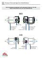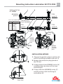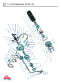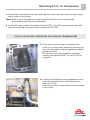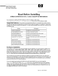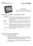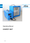
1
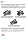
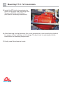
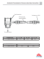
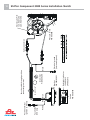
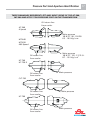
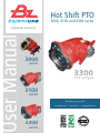
Hot Shift PTO
3000, 3100 and 3300 Series
ser Manual
Hydraulic Systems
3000
series
3300
SAE output
3100
series
Building our world
+1 888 663 1786 • pto-usa.com • [email protected]
3300
series
ES 0303/1998
ES 2001/0353
2
Contents
SAFETY INFORMATION ............................................................................................................................ 3
FOREWORD ............................................................................................................................................... 4
APPLICATION QUESTIONS ........................................................................................................................ 5
1- P.T.O 3100 FOR WORLD TRANSMISSION SERIES
BREAK UP VIEW ....................................................................................................................... 6
MOUNTING PTO TO TRANSMISSION ....................................................................................... 7
MOUNTING PTO TO TRANSMISSION ....................................................................................... 8
SHIFTER COMPONENT INSTALLATION SKETCH....................................................................... 9
PRESSURE PORT AND OPENING IDENTIFICATION ................................................................. 10
LUBRICATION KIT MOUNTING INSTRUCTION ....................................................................... 11
2- P.T.O 3000 SERIES AT, MT, HT
BREAK UP VIEW ...................................................................................................................... 12
MOUNTING PTO TO TRANSMISSION ..................................................................................... 13
MOUNTING PTO TO TRANSMISSION ..................................................................................... 14
AUTOMATIC TRANSMISSION PRESSURE LUBE HOSE CONNECTION .................................... 15
SHIFTER COMPONENT INSTALLATION SKETCH..................................................................... 16
PRESSURE PORT AND OPENING IDENTIFICATION ................................................................. 17
LUBRICATION KIT MOUNTING INSTRUCTION AT500/MT 600/HT 700........................ 18,19,20
3- P.T.O 3300 SERIES ALLLISON / AISIN
BREAK UP VIEW ...................................................................................................................... 21
SHIFTER COMPONENT INSTALLATION SKETCH..................................................................... 22
AISIN- LUBRICATION KIT MOUNTING INSTRUCTION ............................................................ 23
AISIN AS69RC- LUBRICATION KIT MOUNTING INSTRUCTION .............................................. 24
ALLISON 1000, 2000, 2400 TRANSMISSION SERIES ............................................................... 25
PTO SHIFTING PROCEDURE & PRECAUTIONS ........................................................................................ 26
NOTES ...................................................................................................................................................... 27
Safety Information
3
CAUTION:
TO PREVENT POSSIBLE INJURY OR DEATH:
DO NOT go underneath the vehicle with the engine running.
DO NOT attempt to work on an installed Power Take-Off with the engine running.
DO NOT operate the controls of the Power Take-Off or other driven equipment from
underneath the vehicle with the engine running.
DO NOT operate the controls of the Power Take-Off or other driven equipment in any
position that could result in getting caught in the moving machinery.
CAUTION:
Make sure to block any moving or raised device that may injure a person working on or
under the truck. A lever or its linkage may be accidentally moved causing movement of
the device which could cause injury to a person near the device.
IMPORTANT:
Because most of our Bezares Power Take–Offs and P.T.O. drive lines are sold through
distributors, the product applications and the resulting degree of exposure to danger of
the operators are beyond the knowledge and controls of BZ U.S.A.
Therefore, the proper installation of the P.T.O. and its associated equipment, and the
decisions of whether to install guards and/or warning signs shall be the responsibility of
the designers or installers.
! DANGER
NEVER GET
UNDER THE
TRUCK IF
THE ENGINE
IS RUNNING!
You may be
hurt or killed.
! PELIGRO
¡NUNCA SE
META DEBAJO
DEL CAMIÓN
CUANDO EL
MOTOR ESTÉ
EN MARCHA!
4
Foreword
Since it is our major objective to show you how to get additional and more profitable
miles from truck, tractor and trailer components, we want to provide you with
information on the installation of 3000, 3100, and 3300 Series.
We all realize that an inadequate transmission will overwork any Power Take–Off in a
very short period of time. In addition, a mismatched transmission/P.T.O. combination
can result in unsatisfactory performance of the equipment right from the start.
P.T.O. 3100 SERIES
P.T.O. 3000 SERIES
P.T.O. 3300 SERIES
Before you order new trucks be sure that you’re getting the right transmission/P.T.O.
combination. It is of vital importance for efficient performance to have adequate
power. To help you select the proper type, size and design of P.T.O. it is advisable to
discuss your specific requirements with a Bezares P.T.O. specialist. They know their
products and Power Take–Offs. They can inform you about everything you need to
know about power, at the right time, before you specify components.
Aplication Questions
5
Here are some of the questions that are relevant to the Proper Selections of a
Transmission mounted Power Take–Offs.
1.
What is the make and model of your transmission?
2.
Which P.T.O. opening will be used?
3.
What accessory is to be driven?
4.
How much horsepower is required to drive the accessory?
5.
What is the required rotation of the P.T.O.?
6.
What is the required P.T.O. output shaft speed as a percent of engine speed?
Once all of the answer to these questions have been determined, a transmission
mounted P.T.O. can be selected to meet the horsepower, speed and rotation that you
require.
Having made the selection of a P.T.O. you are ready to start the installation.
55
54
53
51
52
50
49
48
18
47
19
46
20
45
21
44
22
43
23
24
42
25
41
26
40
2
27
57
3
28
4
37
5
30
38
29
39
6
56
31
36
7
32
33
8
34
35
9
57
10
11
12
13
14
15
16
17
6
1. P.T.O. 3100 For World Transmission
Mounting P.T.O. To Transmission
1
7
2
1. Drain the oil from the transmission and the PTO aperture cover plate.
2. Discard the cover plate and cover plate gasket, then clean the aperture pad using a
putty knife or wire brush.
Note: Stuff a rag in the aperture opening to prevent dirt from entering the transmission
while you are cleaning it.
3
4
3. Install the proper studs and pins (furnished with the PTO) in the pto aperture pad.
(See also specific mounting instruction furnished with the PTO).
4. Place the steel gasket over studs using grease, if necessary, to keep it in place. The
ribbed surface should face towards the installer. Fit at least 4 nuts in each corner
before checking the backlash. Check the suitable backlash. It should be between
0,006” and 0,015”.
8
Mounting P.T.O. To Transmission
5. Fasten the PTO to the transmission by
means of the bolts and remaining nuts.
6
6. Install the lubrication and engagement
hoses (see specific mounting
instructions pag. 11)
7. Fasten the high pressure line to the
transmission and checking for proper
oil level and signs of oil leakage,
the best check is conducted with the
transmission at operating temperature.
8. Finally install the electrical connection.
7
White
Fuse holder
8/10 Amp
Switch
P/N 9058799
Grommet
P/N-9059299
Red Light Indicator
P/N
12V-903013
24V-902913
Bracket
P/N-200105021
Drill 11/4”
Pass the cable through partition
connector grommet
Red Blue
Positive terminal
(ignation or battery)
INSTALLATION SKETCH HOT SHIFT PTO’S
24V
9058999
Pressure switch
P/N-905999
12V
INSTALLATION KIT P/N 9058899
Electrical ground
(instrument panel)
Black
Valve Connection
Electrovalve
P/N
12V-9067290
24V-9067390
Shifter Component 3100 Series Installation Sketch
9
10
Pressure Port and Aperture Identification
THESE DRAWINGS REPRESENT LEFT AND RIGHT VIEWS OF THE MD
AND HD PRESSURE PORT ON THE TRANSMISION.
MD
ALLISON
10 BOLT PAD
MAIN PRESS. PORT
.438-20 UNF-2A
175 TO 255 P.S.I.
BOTH SIDES
68-TEETH
10.16 PITCH
20° P.A.
19.2654° HELIX L.H.
MAIN PRESS. PORT
.438-20 UNF-2A
175 TO 255 P.S.I.
BOTH SIDES
HD
ALLISON
10 BOLT PAD
97-TEETH
10.16 PITCH
20° P.A.
19.2654° HELIX L.H.
MAIN PRESS. PORT
.438-20 UNF-2A
LEFT SIDE ONLY
Mounting Instruction Lubrication Kit PTO 3100 11
Shifting Kit Part
Nº 900899
GEARBOX
point A
PTO
point B
LIST OF CONTENT Lubrication Kit
Item
1
2
3
4
Description
Fitting
Hose
Fitting
Washer
Part Nº 9018699
PTO
point C
PTO
point D
9018699
9018699
900899
To main
pressure
port
3100 Series
3250 Series
900899
To main
pressure
port
INSTALLATION METHOD
1. Remove the gearbox plug in position (A)
and fit the fitting available in the kit (1)
2. Remove the protection plug placed on
the PTO (B).
3. Fit the pressure Hose (900899) on the (A)
and (B) position by means of the hose
and fitting (3).
4. Fit the Lube hose (9018699) on the (C)
and (D) position with the fitting (3)
and washers (4)
SERIES HD
Rear View
45
44
oil return
line port
from
cooler
43
42
41
40
46
39
1
47
38
2
48
37
35
3
49
36
6
50
34
7
51
33
8
52
32
53
31
9
54
30
55
4
56
10
29
28
57
5
11
58
27
12
13
main
pressure
port
26
14
59
15
18
19
25
16
20
21
22
23
24
17
12
2. P.T.O. 3000 Series AT, MT, HT
Mounting P.T.O. To Transmission 13
1. Discard the cover plate and cover plate gasket, then clean the aperture pad using a
putty knife or wire brush.
Note: Stuff a rag in the aperture opening to prevent dirt from entering the
transmission while you are cleaning it.
2. Install the proper studs (furnished with the PTO) in the PTO aperture pad. See also
specific mounting instructions (furnished with the PTO).
DO NOT USE SEALING COMPOUNDS IN AUTOMATIC TRANSMISSIONS
3. Place the correct number of gaskets over
studs. Do not use paste between because you
may want to add or subtract gasket to obtain
proper backlash.
Do not use more than 3 gaskets together,
Usually one gaskets 0.020” (0.5 mm) will be
required.
4. Install the lubrication and engagement hoses
(specific instructions for each transmission
pag. 18, 19, 20).
Lubrication hose is connected to point coming
from cooler.
14
Mounting P.T.O. To Transmission
5. Install the PTO to the transmission by
means of the bolts and remaining nuts.
Torque to 30-35 lb-ft (41-47Nm).
(See specific mounting instructions).
6. After fastening the high pressure line to the transmission, circuit need to be checked
for proper oil level and signs of oil leakage. The best check is conducted with the
transmission at operating temperature.
7. Finally install the electrical circuit.
Automatic Transmission’s Pressure Lube Hose Connection 15
Tee Connection
To Idler pin in PTO
Pressure Lube
Hose (9018399)
To cooler Return
TRANSMISSION
AT - 500
MT - 600
HT - 700
“T” CONNECTION P/N
FI511
FI511
FI521
TRANSMISSION
“T” CONNECTION P/N
1000 / 2000, 2400
FI831
FI401
White
Fuse holder
8/10 Amp
Red
Positive terminal
ignition or battery
Switch
P/N 9058799
Blue
Drill 1 1/4”
Red Light Indicator
12V 903013
24V 902913
Bracket
P/N 200105021
Grommet
P/N 9059299
Electrical ground
(instrument panel)
Black
Pass the cable through partition
connector grommet
Pressure switch
P/N 905999
Valve connection
Electrovalve P/N
12V - 9067290
24V - 9067390
16
Shifter Component 3000 Series Installation Sketch
Pressure Port And Aperture Identification 17
THESE DRAWINGS REPRESENT LEFT AND RIGHT VIEWS OF THE AT-500,
MT-600 AND HT/CLT-700 PRESSURE PORT ON THE TRANSMISSION
Oil return line
from cooler
AT-540
4 Speed
Main pressure
1/8 N.P.T. 90 - 150 PSI
6.3 - 10.5 Kg / cm2
MT-640
MT-650
4&5 Speed
Oil return line
from cooler
Main pressure
1/8 N.P.T. 125 - 217 P.S.I.
8.7 - 15.2 Kg / cm2
HT-740
HT-750 D
Oil return line
from cooler
Main pressure
CLT-750
Oil return line
from cooler
Main pressure
HT-700
Oil return line
from cooler
Main pressure
Mounting Instructions Lubrication Kit PTO AT500
18
Oil From Cooler
2
1
3
4
3
6
PTO
point B
Lubrication Kit
Part Nº 9018399
3
4
5
LIST OF CONTENT
Description
“T”Description
Fitting
“T” Fitting
O-ring
O-ring
Fitting
Fitting
Hose
Hose
Fitting
Fitting
Washer
Washer
Oil Return Line
From Cooler
6
PTO,
point D
Gearbox
point C
Gearbox
point A
Item
Item
1
21
32
3
44
55
66
6
Shifting Kit
Part Nº 9019499
A
INSTALLATION METHOD
1. Install the “T” fitting (1) into the oil line
returning to the transmission from cooler
(A) position.
2. Connect the lubrication hose (9018399) to
the “T” fitting (1) by means of fitting (3).
3. Connect the lubrication hose to the PTO
(B) position by means of the fitting (3)
C
Main Pressure
Rear view
4. Fit the Pressure hose (9019499) into the
main pressure to the transmission (C)
position, with the fitting (3).
5. Fit the Pressure hose on the (D) position
with the fitting (5) and washers (6).
* After installation of the PTO the transmission should be carefully
checked for proper oil level and signs of oil leakage. The best check
is conducted with the transmission at operating temperature.
Mounting Instructions Lubrication Kit PTO MT600 19
Oil From Cooler
1
2
3
4
3
6
PTO,
point B
Lubrication Kit
Part Nº 9018399
GEARBOX
point A
3
4
5
GEARBOX
point C
LIST OF CONTENT
Item
Item
1
1
2
3
3
4
4
5
5
6
6
6
6
PTO,
point D
Shifting Kit
Part Nº 9019499
Description
Description
“T”
Fitting
“T” Fitting
O-ring
O-ring
Fitting
Fitting
Hose
Hose
Fitting
Fitting
Washer
Washer
D
B
INSTALLATION METHOD
1. Install the “T” fitting (1) into the oil line
returning to the transmission from cooler
(A) position.
2. Connect the hose (9018399) to the “T”
fitting (1) by means of fitting (3).
3. Connect the lubrication hose to the PTO
(B) position by means of the fitting (3)
C
MAIN PRESSURE
Oil Return Line
From Cooler
Rear view
A
4. Fit the Pressure hose (9019499) into the
main pressure to the transmission (C)
position, with the fitting (3).
5. Fit the Pressure hose on the (D) position
with the fitting (5) and washers (6).
* After installation of the PTO the transmission should be carefully
checked for proper oil level and signs of oil leakage. The best check
is conducted with the transmission at operating temperature.
20
Mounting Instructions Lubrication Kit PTO HT700
Oil From Cooler
1
2
3
4
3
6
PTO
point B
Lubrication Kit
Part Nº 9018399
GEARBOX
point A
3
4
5
GEARBOX
point C
LIST OF CONTENT
Item
Item
1
1
22
33
44
55
6
6
6
6
PTO
point D
Shifting Kit
Part Nº 9019499
Description
Description
“T” Fitting
“T” Fitting
O-ring
O-ring
Fitting
Fitting
Hose
Hose
Fitting
Fitting
Washer
Washer
D
B
A
INSTALLATION METHOD
1. Install the “T” fitting (1) into the oil
line returning to the transmission from
cooler (A) position.
2. Connect the lubrication hose (9018399) to
the “T” fitting (1) by means of fitting (3).
3. Connect the lubrication hose to the PTO
(B) position by means of the fitting (3)
C
Oil return line
from cooler
Main Pressure
4. Fit the Pressure hose (9019499) into the
main pressure to the transmission (C)
position, with the fitting (3).
5. Fit the Pressure hose on the (D) position
with the fitting (5) and washers (6).
Rear view
* After installation of the PTO the transmission should be carefully
checked for proper oil level and signs of oil leakage. The best check
is conducted with the transmission at operating temperature.
oil return
line port
from
cooler
62
66
30
29
61
28
60
59
58
32
55
10
56
31
63
57
64
34
53
11
12
13
14
35
52
main
pressure
port
33
54
INPUT GEAR
"A" AND "Z " RATIO
INPUT GEAR
"B" RATIO ONLY
68
67
65
15
36
51
16
17
37
50
48
38
49
46
2
18
39
1
47
3
19
40
45
4
41
44
5
20
7
21
6
42
43
8
9
22
23
24
25
26
27
3. PTO 3300 SERIES 21
White
Fuse holder
8/10 Amp
Red
Positive terminal
ignition or battery
Switch
P/N 9058799
Blue
Drill 1 1/4”
Pressure switch
P/N 905999
Electrical ground
(instrument panel)
Black
Wire connections
P/N 9059199
Red Light Indicator 12V
903013
24V 902910
Bracket
P/N 200105021
Grommet
P/N 9059299
Pass the cable through
partition connector grommet
Valve
connection
Electrovalve P/N
12V - 9067290
24V - 9067390
22
Shifter Component 3300 Series Installation Sketch
Shifter Instructions Lubrication Kit PTO AISIN 23
1
2
3
4
Engagement Kit
Part Nº 9041399
GEARBOX,
point A
PTO
point B
Lubrication Kit
Part Nº. 9041499
1
5
6
4
PTO
point D
GEARBOX,
point C
C
A
GEARBOX
Viewed from top side
GEARBOX
Viewed from left side
LIST
OFOF
CONTENT
LIST
CONTENT
Item
Item
11
22
3
34
45
56
6
Lubrication Kit
9041499
Description
Description
Fitting 1/2”
UNF
Fitting
1/2”
UNF
Engagement hose
Engagement
hose
Fitting M10x1
Fitting
M10x1
Washer
Washer
Lubrication hose
Fitting 1/8” BSP
Lubrication
hose
Fitting 1/8” BSP
B
INSTALATION METHOD
INSTALLATION
1.- Remove the METHOD
gearbox plug
“A” and the
“C” position.
1. in
Remove
gearbox plug in “A” and
2.- Remove
the protection
“C”
position
plugs placed on the PTO in “B”,
2. Remove
the protection plugs placed on
and “D” position.
the
PTO
“B” and “D”
3.- Fit
thein
engagement
kit position.
(9041399) in “A” and “B” position.
3. Fit
engagement
4.- the
Fit the
lubrication kitkit (9041399) in “A”
and
“B” position
(9041499)
in “C” and “D” position.
4. Fit the lubrication kit (9041499) in “C”
and “D” position.
D
PTO
Engagement kit
9041399
24
Mounting Instructions Lubrication Kit PTO AISIN AS69RC
(DODGE RAM Vehicles)
Engagement Kit
Part Nº 9041399
PTO
point B
GEARBOX
point A
Lubrication Kit
Part Nº 9041499
PTO
point D
GEARBOX
point C
C
GEARBOX
viewed from left side
A
Lubrication kit
9041499
LIST OF CONTENT
Item
1
2
3
4
5
6
Description
Fitting 1/2” UNF
Engagement hose
Fitting M10x1
Washer
Lubrication hose
Fitting 1/8” BSP
INSTALLATION METHOD
1. Remove the gearbox plug in “A”
and “C” position
2. Remove the protection plugs placed
on the PTO in “B” and “D” position.
Engagement kit
9041399
3. Fit the engagement kit (9041399)
in “A” and “B” position
4. Fit the lubrication kit (9041499) in
“C” and “D” position.
Mounting Instructions Lubrication Kit PTO
25
Allison/1000/2000/2400
Oil from cooler
PTO
point A
Lubrication Kit part Nº 9019199
Option 1 (3/4" - 16 UNF)
Option 2 (7/8" - 14 UNF)
Option 3 (1 1/16" - 12 UNF)
GEARBOX
point D
GEARBOX
point C
LIST OF CONTENT
Item
1
2
3
4
5
6
PTO
point B
Engagement Kit part Nº 900899.1
Description
“T” Fitting
O-ring
Fitting
Hose
Fitting
Washer
Lubrication Kit
9019199
INSTALLATION METHOD
1. Install the “T” fitting (1) into the oil line
returning to the transmission from cooler
(point C).
2. Connect the hose (9019199) to the “T”
fitting (1) by means of fitting (3).
3. Connect the lubrication hose to the PTO
(A) position by means of the fitting (5) and
washers (6).
4. Fit the Pressure hose (900899.1) into the
main pressure to the transmission (D)
position, with the fitting (3).
Engagement Kit
900899.1
5. Fit the Pressure hose on the (B) position
with the fitting (5) and washers (6).
PTO
* After installation of the PTO the transmission
should be carefully checked for proper oil level and
signs of oil leakage. The best check is conducted
with the transmission at operating temperature.
(Main pressure port
0,438-20UNF)
Gearbox, bottom view
26
P.T.O. Shifting Procedure & Precautions
CAUTION: This vehicle is equipped with a Power Take-Off. Shut engine off before
working on the Power Take-Off or getting below the vehicle.
Consult the operating instructions before using the P.T.O. (see sun visor)
POWER TAKE-OFF OPERATION - VEHICLE STATIONARY
Automatic Transmission with Power Shift P.T.O.’s
Engage the P.T.O. with the engine at idle speed.
NOTE: Power Shift P.T.O.´s: The engine must be at idle or below 1000 RPM when
the P.T.O. is engaged. See the transmission manufacturer’s instructions for special
procedures.
IMPORTANT:
Failure to follow the proper shifting or operating sequences will result in
premature P.T.O. failure with possible damage to other equipment.
Warning: Cold Weather Operation of Power Shift P.T.O.´s
During extreme cold weather operation [32°F (0°C) and lower], a disengaged Power
Shift Power Take-Off can momentarily transmit high torque that will cause unexpected
output shaft rotation. This is caused by the high viscosity of the transmission oil when it
is extrememly cold. As slippage occurs between the Power Take-Off clutch plates, the oil
will rapidly heat up and the viscous drag quickly decreases.
The Power Take-Off output shaft rotation could cause unexpected movement of the
driven equipment, resulting in serious personal injury, death, or equipment damage.
To avoid personal injury or equipment damage:
- Driven equipment must have separate controls.
- Driven equipment must be left in the disengaged position when not in operation.
- Driven equipment must not be operated until the vehicle is allowed to warm up.
Notes
27
28
Notes
27634 Commerce Oaks Drive
Oak Ridge north, Texas 77385
+1 888 663 1786
[email protected]
BZUM3000-07/2015