1
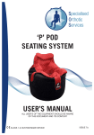
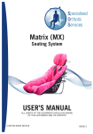
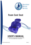
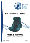
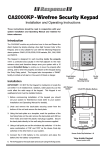
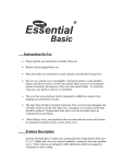
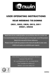
BM SEATING SYSTEM
USER’S MANUAL
ALL USER’S OF THE EQUIPMENT SHOULD BE AWARE
OF THIS DOCUMENT AND ITS CONTENT
| CLASS 1 DEVICE
ISSUE 3
Index
CONTENTS
Index
PAGE
1
Introduction
2
Description
2
Clinical Review
3
Stability of Buggy/Wheelchair & Seating Systems
3&4
Recommendations on Transport
4
1.0
User’s Guide “Fitting the BM Seating System”
1.1
Fitting the BM Seating System to the Wheelbase
2.0
User’s Guide “Lifting and Handling the Client”
2.1
Placing the Client in the BM System
6
2.2
Fastening the Harness and Securing the Client
6
2.3
Footrest Fitting & Adjustment
7
2.4
Upholstery
7
3.0
User’s Guide “Setting up of the BM”
3.1
Adjusting the BM Seat
8
3.2
Adjusting the Seat Depth
8
3.3
Adjusting the Headrest
9
3.4
Adjusting the Hip Pads
9
3.5
Adjusting the Lateral Pads
10
3.6
Adjusting the Client Harness
11
4.0
User’s Guide “Maintenance of the BM”
4.1
Cleaning the BM System
12
4.2
Clean the BM System Covers
13
4.3
Harness, Pads & Straps
13
4.4
Visual Inspection
13
4.5
Fire Retardancy
13
“If You Detect a Fault or Breakage”
CONTACT DETAILS
1
5
14
Backpage
B.M. SEATING SYSTEM
(Class 1 Device)
Introduction
•
The user’s guide for the BM Seating System is designed to give guidance on it’s use
and maintenance.
Description
• The BM Seating System is a Modular Seating System intended to provide a variable
•
•
•
amount of external support to establish a stable sitting position.
The BM Seating System is available in one size that can be adjusted via growth liners
to accommodate different sizes.
The BM Seating System is intended for use by children from 12 months of age and
upwards.
It is important that children are assessed by a suitably qualified clinician with
experience in the provision of SPECIALISED SEATING. Contact your local
Wheelchair Service who will be able to offer advice regarding the provision of
SPECIALISED SEATING.
Basic Components of the
BM System
A
A.
B.
C.
D.
E.
C
Velcro Retention Straps
Shell
Head Pad
Lateral Thoracic Pads
Back Rest
E
D
B
G
J
A
F
A
D
J
H
A
K
F.
G.
H.
J.
K.
2
Cushion with Integral Pommel
5 Point Harness
Adjustable Footrest Location
Hip Pads
Footrest
Clinical Review
• To ensure the BM System continues to meet the clinical requirements of the client, it is
•
•
recommended that the system is reviewed by the Special Seating Clinic at least once
a year.
This may be done automatically by your District Wheelchair Service.
If a client has had a BM System over 12 months it is recommended that you contact
the District Wheelchair Services for a review. This will ensure that the BM System is
maintaining the clinical needs of the client.
Stability of Buggy/Wheelchair and Seating Systems
• To ensure that the BM System and wheelbase are safe to use, it is important that
•
•
•
•
•
•
•
•
fitting the BM System to the wheelbase does not make the wheelbase unstable during
normal daily use. Each BM System when handed over to the user will be tested for
stability to the relevant angle of stability for the chair to be tested.
The recommended maximum angle of tilt is 12 degrees for attendant transit
wheelchairs and 16 degrees for users of self propelling wheelchairs and 16 degrees
for users of electric indoor and outdoor
electric wheelchairs.
If the client is going to use additional items
mounted to the wheelbase or seating
system such as communications aids etc.,
then it is essential that the test be done
with these in situ to access their impact
on the safety of the wheelbase. Similarly,
simple items such as trays need to be in
place for the test to take into account all
the equipment to be used by the client (see
diagram opposite).
16°
The stability test is always done with the
12°
client seated in the seating system and all
equipment to be used by the client on a
daily basis when in the seating system in situ. The combined client Seating System
and wheelbase assembly is tested to the specified maximum angle of tilt.
Once the test has been successfully completed a Stability Certificate will be issued
by Specialised Orthotic Services Limited. A copy of this certificate will be handed over
when the equipment is supplied and should be kept with the user manual for future
reference.
The BM is not to be used with any other wheelbase(s) than those for which it
has been stability tested and proven safe for use.
Always steer clear of obstacles where possible.
When using the equipment never attempt to climb or descend an incline where
the surface is rough, wet or slippery (gravel, loose chippings, grass, rain, ice,
snow, etc).
If the equipment is to be used in an electric wheelchair then read carefully the
wheelchair manufacturers instructions with regard to safety.
3
Stability of Buggy/Wheelchair and Seating Systems (Cont.)
• WARNING: Whilst the client is seated in the seating system, the attachment of
any heavy object to the wheelbase (i.e. shopping bags etc.) will have a serious
effect on the overall stability of the wheelbase and may place the safety of the
client at risk.
Stowage of the Seating System and Wheelchair
•
•
•
•
During use of your Special Seating System it may be necessary for you to remove the
Seating System and stow this along with the wheelchair in a vehicle.
It is important to realise that these items pose a risk if not adequately restrained
whilst in transit.
It is not adequate to simply place the items into a car boot or the floor of an open
vehicle such as an MPV or estate car as in a collision these unsecured items could
cause serious injury to occupants of the vehicle.
Various retention methods are available to secure such equipment during transit, and
a list of Wheelchair Restraint System Manufacturers are listed below.
W.T.O.R.S MANUFACTURERS
Below are details of some Wheelchair Tie down and Occupant Restraint Systems
manufacturers.
UNWIN SAFETY
SYSTEMS
Unwin House
The Horseshoe
Coat Road
Martock
Somerset
TA12 6EY
TEL: 01935 827740
FAX: 01935 827760
E Mail: [email protected]
KOLLER
ENGINEERING LTD
Unit 5, Garrett Road
Lynx Trading Estate
Yeovil
Somerset
BA20 2TJ
TEL: 01935 426695
FAX: 01935 433766
E MaiI: [email protected]
QSTRAINT
(EUROPE)
Unit 175
John Wilson Business Park
Whitstable
Kent
CT5 3RB
TEL: 01227 773035
FAX: 01227 770035
E MaiI: [email protected]
SAFETEX
Unit 16 / 17
Bookham Industrial Park
Church Road
Bookham
Surrey
KT23 3EU
TEL: 01372 451272
FAX: 01372 451282
E Mail: [email protected]
4
USER GUIDE 1.0
1.1. FITTING THE BM SEATING SYSTEM TO THE WHEELBASE.
• To fit the BM System correctly
•
•
•
into the wheelbase is important
for the clients safety.
B
Make sure the velcro retaining
straps ‘1’ (Fig.1.1a) are undone
before fitting the BM Seat into
the wheelbase.
Place the seat into the
wheelbase making sure that
it is right back on the seat
canvass
1
Feed the two broad velcro
straps around the wheelbase
seat and overlap firmly to
secure the BM seat in position
1
A
Fig.1.1a
Fig.1.1b
Fig.1.1c
View on ‘A’
View on ‘B’
5
USER GUIDE 2.0
2.1. PLACING THE CLIENT IN THE BM SEAT
• It is important that all carers are aware of the Health & Safety guidelines for ‘Lifting
•
•
•
and Handling’.
Before lifting the client make sure all straps are placed out of the BM System. This will
avoid the straps becoming trapped under the client when seated.
With all the client harness straps released an placed outside the seat the client can
now be placed in the seat.
It is very important that the pelvis is positioned right back into the back of the seat
base, failure to do so may well detract from the sitting posture achieved.
2.2. FASTENING THE HARNESS AND SECURING THE CLIENT
• Once the client is placed, secure the
•
•
harness around the client, joining
the straps at the release button ‘2’
and pulling the straps through the
cam buckles (Fig.2.2b) until correctly
adjusted, then close the cam buckles.
1
3
For extra adjustment pull or release
the shoulder straps via the ‘D’ rings
(Fig.2.2a).
A
Overlap the velcro band ‘3’ attached to
the lateral supports (Fig.2.2c) across
the front of the client and close the
velcro together.
2
3
1 - ‘D’ Rings
2 - Release Button
3 - Lateral Support Velcro Band
Fig.2.2a
Fig.2.2b
Fig.2.2c
View on ‘A’
6
2.3. FOOTREST FITTING & ADJUSTMENT
• If the adjustable footrest is to be used this can be
•
•
attached easily by inserting the footrest bracket
into the locating socket at ‘H’ (Fig.2.3a), the
footrest is secured by turning the locking knob
(Fig.2.3b) in a clockwise direction until locked.
The footrest is easily detached by turning the
locking knob anti-clockwise 4 or 5 turns to
release the lock and slide the locating bracket
out.
With the client safely seated as instructed the
footrest can be simply adjusted by releasing the
vertical (Fig.2.3c) and horizontal (Fig.2.3b) wing
knobs.
Fig.2.3b
Fig.2.3a
Fig.2.3c
2.4. UPHOLSTERY
• All the support pads fitted to the BM System are attached by Velcro. The pads have
fitted covers and these can be removed by simply unzipping the cover.
7
USER GUIDE 3.0
3.1. ADJUSTING THE BM SEATING SYSTEM
• The BM is provided with removable growth pads that allow the seating system to be
adjusted to suit the original size of the client when assessed and also to allow for
growth or comfort.
3.2. ADJUSTING THE DEPTH OF SEAT (Leg Length)
• If the harness goes through the back panel and
•
•
•
packers then release the upper cam locks on
the harness (See 3.6) and pull the upper straps
(Fig.3.2a) through the seat shell and all the back
panels.
Remove the complete back panel assembly
including all pads (Fig.3.2b).
Refit the amount of packers you require (if
any) and then refit the upholstered back panel
(Fig.3.2c).
Refit harness straps (See 3.6).
Fig.3.2a
Fig.3.2b
Fig.3.2c
8
3.3. ADJUSTING THE HEADREST
• If the harness goes through the headrest pads
•
•
•
•
and packers, then release the upper cam locks
on the harness (See 3.6) and pull the upper
straps (See 3.6)) through the seat shell and all
the back headrest pads.
Remove the headrest (Fig.3.3a) then remove the
complete headrest pad assembly including all
pads (Fig.3.3b).
Refit the amount of packers you require (if any)
then refit the upholstered headrest pad and
headrest (Fig.3.3c).
Fig.3.3a
Refit harness straps (See 3.6).
Headrest can be set at any height along the headrest pad via the velcro strips to find
the correct position for the client.
Fig.3.3b
Fig.3.3c
3.4. ADJUSTING THE HIP PADS (Thigh Width)
• Remove the upholstered pad (Fig.3.4a), remove the amount of pads you do not
require (Fig.3.4b) then refit the upholstered pad.
Fig.3.4a
Fig.3.4b
9
3.5. ADJUSTING THE LATERAL PADS (Width & Height)
• If the harness goes through the back panels and
•
•
•
•
•
packers, then release the upper cam locks on
the harness (See 3.6) and pull the upper straps
(Fig.3.5a) through the seat shell and all the back
panels.
Remove the complete back panel assembly
including all pads (Fig.3.5b).
Release the straps (Fig.3.5c) from the rear of the
pads.
Reposition the lateral pads (Fig.3.5d) and secure
the strap around the back of the pads.
Refit the back panel assembly and secure the
chest strap (Fig.3.5e).
Fig.3.5a
Refit harness straps (See 3.6).
Fig.3.5b
Fig.3.5c
Fig.3.5d
Fig.3.5e
10
3.6. ADJUSTING THE HARNESS (Height)
• Press the red button (Fig.3.6a) in the centre of
•
•
•
•
the buckle to release the straps.
Release all the cam buckles (Fig.3.6b) at the rear
and under the shell and pull out the two upper
straps.
Re-insert the straps through all the corresponding
pads (Fig.3.6c) at the required height and through
the corresponding slot in the shell (Fig.3.6d).
Adjust the strap lengths to roughly the correct
length and close the cam buckles (Fig.3.6e).
Finally follow the procedure for fastening the
harness and securing the client (See 2.2)
Fig.3.6a
Fig.3.6b
Fig.3.6c
Fig.3.6d
Fig.3.6e
11
USER GUIDE 4.0
MAINTENANCE OF THE BM SYSTEM
To make sure that the BM System remains satisfactory it is necessary to carry out simple
maintenance.
4.1. CLEANING THE BM SYSTEM
• During use the BM System will require cleaning. This can be done by simply applying
•
•
•
•
•
a warm damp cloth with a mild detergent to the inside surface of the seat to remove
any soiling and towel dry. Note: The covers/pads MUST be removed prior to any
cleaning of the seat.
If the BM System remains slightly damp simply leave for a short period at room
temperature to dry.
The inner Foam pads on the BM System are made from an open cell foam, which will
absorb water. DO NOT get these excessively wet as the foam will be a problem to dry.
The cushion foam is sealed in a special water proof clear plastic protective skin
which although waterproof is air permeable to assist daily management. Under no
circumstances is the clear protective skin to be removed as the foam will have no
protection against contamination and will need to be replaced. If the plastic skin
becomes seriously damaged contact SOS immediately. To clean the cushion pad,
simply wipe down with mild detergent and a damp cloth and towel dry and leave at
room temperature to dry thoroughly. Under no circumstances use excessive heat to try
to dry the foam as this could damage the protective skin.
DO NOT PUT THE BM SYSTEM NEXT TO A HOT FIRE OR USE EXCESSIVE HEAT
TO DRY AS EXCESSIVE HEAT COULD AFFECT THE COMPONENTS OF THE
SEAT.
DO NOT USE SCOURERS OR CAUSTIC SUBSTANCES SUCH AS BLEACH
12
4.2. REMOVABLE COVERS
• For cleaning of removable covers please refer to wash label on the inside of the
•
•
padded cover.
DO NOT REMOVE THE FOAM FROM THE WATERPROOF LINER OR TRY TO
WASH IT AS THIS FOAM WILL ABSORB WATER AND WILL BE A PROBLEM TO
DRY OUT.
ANY DEVIATIONS FROM THE WASH LABEL MAY AFFECT THE FIRE
RETARDANCY OF THE COVER(S).
4.3. HARNESSES, PADS & STRAPS
• Make sure all straps are in good working order and that buckles work correctly.
• If any show signs of fraying or any buckles are broken or faulty contact your
•
Wheelchair Service immediately, DO NOT ATTEMPT TO REPAIR.
Harnesses may be cleaned by applying a warm damp cloth with a mild detergent,
DO NOT USE POLISH.
4.4. VISUAL INSPECTION
• Every 3 - 4 weeks check the condition of the BM System and wheelchair, if you notice
any faults or broken parts please notify your Wheelchair Service immediately, DO NOT
ATTEMPT TO REPAIR.
4.5. FIRE RETARDANCY
• Fire retardant materials have been used in the construction of this seating system.
• It is important that no accelerants are introduced to the materials (e.g. Hairspray, fabric
cleaners, deodorants, polish etc..), as this may adversely affect the fire retardancy of
your equipment.
13
IF YOU DETECT A FAULT OR BREAKAGE
1. IF YOU DETECT A FAULT OR BREAKAGE OF THE EQUIPMENT THEN REPORT
THIS IMMEDIATELY.
2. UNDER NO CIRCUMSTANCES ARE ANY MODIFICATIONS / ALTERATIONS TO BE
DONE BY ANYONE OTHER THAN SPECIALISED ORTHOTIC SERVICES LTD (see
contact details enclosed).
3. TO CONTACT SPECIALISED ORTHOTIC SERVICES LTD PLEASE REFER TO THE
INFORMATION INCLUDED IN THIS USER MANUAL.
REPAIRS & SERVICE
Within the warranty period.
All Seating Systems manufactured by Specialised Orthotic Services Ltd. carry a guarantee
on the main parts for 12 months, excluding covers and straps which are guaranteed for
3 months, when used normally. If during this period the product becomes defective and
needs repair then please contact SOS (please see the end of this users guide for details).
You can also contact your local wheelchair service regarding any faults requiring attention.
Outside the warranty period.
For any goods requiring repair or attention after the guaranteed period, then assessment
can be made as to the cost of the work required to effect the repair.
On acceptance of this quotation the work will proceed.
Misuse or neglect.
The repairs necessary resulting from misuse or neglect, whether within the warranty
period or not will be charged for.
MEDICAL DEVICES DIRECTIVE 93 / 42 EEC
Specialised Orthotic Services Ltd. in compliance with the Medical Devices Directive
have an obligation to investigate and take corrective action on defective devices. To assist
us with this procedure we would appreciate your assistance in meeting this obligation by
informing us as soon as possible and make the device available for inspection as soon as
possible having become aware of a defect.
We are required to notify the Competent Authority of certain types of incidents within 10 to
30 days.
As part of our quality system we have established procedures to deal with such incidences
and would appreciate your swift notification to us via our telephone, fax or e-mail details at
the end of this users manual.
14
If you require further copies of this handout or require further details relating to any of its
content, then please contact us (Copyright applies):
Units 127/128, Fauld Industrial Park, Tutbury, Staffordshire. DE13 9HS
Tel: 0044 (0)1283 520400 Fax: 0044 (0)1283 520401
E-mail: [email protected]
Web: www.specialisedorthoticservices.co.uk