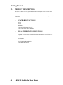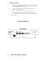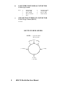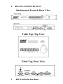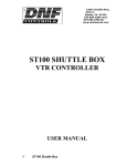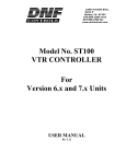
1
12843 Foothill Blvd.,
Suite D
Sylmar, CA 91342
818 898 3380 voice
818 898 3360 fax
www.dnfcontrols.com
MAV-70 Shuttle Box
USER MANUAL
Please note:
MAV70XG1 Video Server requires:
Decoder Board –2.60 or higher
SYSMain Board – 2.60 or higher
MAV70 Video Server requires:
Decoder Board – 2.60 or higher
SYSMain Board – 2.60S or higher
BZA820 Software Application must be:
Version 2.01 or higher
1
MAV-70 Shuttle Box User Manual
TABLE OF CONTENTS
1.
REVISION HISTORY
3
GETTING STARTED . . .
4
2.
PRODUCT DESCRIPTION
4
a.
b.
4
4
3.
4.
STANDARD FUNCTIONS
REAL-TIME STATUS INDICATORS
INSTALLATION
OPERATION
SHUTTLE BOX OPERATION
5
6
6
REFERENCE . . .
7
5.
SPECIFICATIONS
7
a.
b.
c.
d.
e.
FRONT PANEL
REAR PANEL CONNECTORS
MAV-70 RS422 SERIAL CONNECTOR
LOOP THRU RS422 SERIAL CONNECTOR
GPI (KEYPAD) INTERFACE CONNECTOR
7
7
7
8
8
HOUSING CONFIGURATIONS
DNF CONTROLS LIMITED WARRANTY
9
10
6.
7.
Manual Version ……………………..……………… 3.4 010804
Document No. ….….. MAV-70_Shuttle_Box_User_Manual.doc
2
MAV-70 Shuttle Box User Manual
1.
3
REVISION HISTORY
Rev. 3.1 070703
Added statement on cover advising the video server must have Decoder and
SYSMain Board versions of 2.60 or higher.
Rev. 3.2 072903
Changed cover to list video server requirements and software application.
Rev. 3.3 010804
Added DNF Controls Limited Warranty.
MAV-70 Shuttle Box User Manual
Getting Started . . .
2.
PRODUCT DESCRIPTION
The MAV-70 Shuttle Box adds jog and shuttle wheel capability to facilitate control of the
MAV-70 Video Server.
The Shuttle Box automatically switches controls between the automation control system and the
Shuttle Box.
a.
STANDARD FUNCTIONS
PLAY
STOP
REWIND
FAST FORWARD
JOG/SHUTTLE MODE SELECT
JOG & SHUTTLE with the WHEEL
b.
REAL-TIME STATUS INDICATORS
The MAV’s status response is read by the Shuttle Box and the status indicators are
updated to reflect the current state of the VTR.
PLAY
STOP/STILL
REWIND/REVERSE
FAST FORWARD/FORWARD
JOG MODE SELECTED
4
MAV-70 Shuttle Box User Manual
3.
INSTALLATION
a.
Plug one end of a standard 9-conductor, RS422 serial cable into the 9-pin connector on
the rear of the MAV-70 Shuttle Box labeled “MAV-70.” Plug the other end of the cable
into the 9-pin REMOTE connector on the MAV-70.
b.
Plug the 9-pin D-female connector on the POWER SUPPLY into the male 9-pin
connector on the rear of the Shuttle Box.
Plug the AC connector into a wall outlet, 90 VAC - 265 VAC, 50-60 Hz.
c.
Connect the automation system to the 9-pin female connector, on the back of the
MAV-70 Shuttle Box, labeled “Loop-Thru,” using a standard 9-pin, RS422 Serial Cable.
Installation is completed.
Connection Diagram
5
MAV-70 Shuttle Box User Manual
4.
OPERATION
Select the desired transport function by pressing the appropriate switch on the front of the Shuttle
Box. The display shows: “MAV-70 Shuttle Box”
SHUTTLE BOX OPERATION
The Shuttle Box automatically determines whether the Shuttle Box or automation system gets
control of the MAV-70 using the following rules:
6
a.
Normally, the automation system is always in control over the MAV-70.
b.
When any function switch is pressed on the Shuttle Box or the Wheel is moved, the
LOOP-THRU is turned off, disabling the automation system. The Shuttle Box now has
control of the MAV-70. After the selected function is executed or after a 2.5-second
delay, the LOOP-THRU is again turned on, allowing the automation system to control
the MAV-70.
c.
When the LOOP-THRU is turned on, the Shuttle Box monitors communications between
the MAV-70 and the automation system. The MAV’s status response is read by the
Shuttle Box and the status indicators are updated to reflect the current state of the VTR.
MAV-70 Shuttle Box User Manual
Reference . . .
5.
SPECIFICATIONS
Physical –
a.
FRONT PANEL
b.
c.
6 Status LEDs
Play, Stop, Rewind, FFwd, Jog
1 Power LED
3 Direction LEDs
Indicates direction of Jog/Shuttle
Switches
Play, Stop, Rewind, Fast Forward, Jog, Shift, Reset
Display
2-Line LCD, back lit with adjustable contrast
Jog/Shuttle Wheel Size
19” x 5” x 1-3/4” (Rackmount)
7”x 5”x 1 1/2” (Table Top)
Weight
2 lbs.
REAR PANEL CONNECTORS
MAV-70 RS422
9-Pin D-type connector, female (DB9-F)
Power:
5-volt D.C., 500 ma. 90-265 VAC, 50/60 Hz converter
supplied (Rack Mount or Tabletop)
GPI
15-pin D-type connector, female (DB15F)
Switch Input: SPST contact closure, momentary
Status Output: Open collector, sink 50mA.
MAV-70 RS422 SERIAL CONNECTOR
9-Pin D-Type, Female
Pin #
7
1
2
3
4
5
Frame Ground
Receive A Í
Transmit B Î
Transmit Common
Spare
6
7
8
9
MAV-70 Shuttle Box User Manual
Receive Common
Receive B Í
Transmit A Î
Frame Ground
d.
LOOP THRU RS422 SERIAL CONNECTOR
9-Pin D-Type, Female
Pin #
e.
1
2
3
4
5
Frame Ground
Transmit AÎ
Receive B Í
Receive Common
Spare
6
7
8
9
Transmit Common
Transmit B Î
Receive A Í
Frame Ground
GPI (KEYPAD) INTERFACE CONNECTOR
15-Pin, D-Type, Female (DB15-F)
Not used.
SHUTTLE WHEEL SPEEDS
NOTE- ( ) represents Shuttle
Reverse speeds
STILL
( -4 x Play)
4 x Play
16 x Play
( -16 x Play)
8
MAV-70 Shuttle Box User Manual
6.
HOUSING CONFIGURATIONS
Rackmount, Front & Rear View
Table Top, Top View
Table Top, Rear View
9
MAV-70 Shuttle Box User Manual
7.
DNF CONTROLS LIMITED WARRANTY
DNF Controls warrants its product to be free from defects in material and workmanship for a period of one
(1) year from the date of sale to the original purchaser from DNF Controls.
In order to enforce the rights under this warranty, the customer must first contact DNF’s Customer Support
Department to afford the opportunity of identifying and fixing the problem without sending the unit in for
repair. If DNF’s Customer Support Department cannot fix the problem, the customer will be issued a
Returned Merchandise Authorization number (RMA). The customer will then ship the defective product
prepaid to DNF Controls with the RMA number clearly indicated on the customer’s shipping document.
The merchandise is to be shipped to:
DNF Controls
12843 Foothill Blvd., Suite D
Sylmar, CA 91342
USA
Failure to obtain a proper RMA number prior to returning the product may result in the return not being
accepted, or in a charge for the required repair.
DNF Controls, at its option, will repair or replace the defective unit. DNF Controls will return the unit
prepaid to the customer. The method of shipment is at the discretion of DNF Controls, principally UPS
Ground for shipments within the United States of America. Shipments to international customers will be
sent via air. Should a customer require the product to be returned in a more expeditious manner, the return
shipment will be billed to their freight account.
This warranty will be considered null and void if accident, misuse, abuse, improper line voltage, fire, water,
lightning or other acts of God damaged the product. All repair parts are to be supplied by DNF Controls,
either directly or through its authorized dealer network. Similarly, any repair work not performed by either
DNF Controls or its authorized dealer may void the warranty.
After the warranty period has expired, DNF Controls offers repair services at prices listed in the DNF
Controls Price List. DNF Controls reserves the right to refuse repair of any unit outside the warranty
period that is deemed non-repairable.
DNF Controls shall not be liable for direct, indirect, incidental, consequential or other types of damage
resulting from the use of the product.
###
10
MAV-70 Shuttle Box User Manual