1
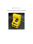
Pocket PiGRRL
Created by Ruiz Brothers
Last updated on 2015-10-21 12:42:15 PM EDT
Guide Contents
Guide Contents
Overview
2
6
Raspberry Pi
This Guide
Prerequisite Guides
Parts
Tools
Supplies
7
7
8
9
9
10
Circuit Diagram
11
Powerboost 1000c
PAM8302
Perma-Proto Two Button Layout
PiTFT Buttons
Perma-Proto Four Button Layout
Half size Perma-Proto
GPIO Ribbon Cable
Software
15
Download and Burn SD Card
Setup Network
Adding More Games
Adding Four Button Controls
Configuring RetroArch Emulators Controls
Software [Manual]
15
15
15
15
17
18
Initial Run
Download and Burn SD Card
Testing Retrogame
Raspi-Config
Network
PiTFT Setup
Edit Config.txt
Mapping Controls
3D Printing
18
18
18
18
19
19
20
20
22
Two Button Version
Four Button Version
Parts
Support material
© Adafruit Industries
11
12
12
13
13
13
14
22
22
23
24
https://learn.adafruit.com/pocket-pigrrl
Page 2 of 112
Tolerances
Materials
Warping
First layer + Bed Leveling
Ninjaflex buttons
Quality Prints
Magnets
24
25
25
25
25
26
26
Wiring
28
Prep Wiring
Cut, Strip, Tin, Repeat
The Slide Switch
Powerboost 1000C
PAM8302 & Speaker
2.4' PiTFT
Perma-proto
28
28
28
29
30
31
32
Switch
33
Prepping Slide Switch
Secure Slide Switch
Wire Slide Switch
Heat Shrink Slide Switch
Install Slide Switch
33
34
36
37
37
Powerboost 1000C
40
Prep PowerBoost 1000C
Wire Powerboost 1000C
Thread Mounting Holes
Install PowerBoost 1000C
Mount PowerBoost 1000C
Test PowerBoost 100C
40
41
42
43
44
45
PAM8302
46
Prep PAM8302
PAM8302 Wires
Thread PAM8302
Solder Wires to PAM8302
Mount PAM to enclosure
Solder power to PAM8302
46
46
48
49
49
51
Pi Audio
52
Cut Pi Audio wires
Strip and Tin Wires
Tin Audio pins on Pi
© Adafruit Industries
52
53
54
https://learn.adafruit.com/pocket-pigrrl
Page 3 of 112
Solder Audio Wires to Pi
Solder Audio wires to PAM8302
Mount Pi
Mounted Pi
Speaker
59
Prep Metal Speaker
Prep New Wires for Speaker
Solder Wires to Speaker
Install Speaker
Connect Speaker wires to PAM8302
2.4 PiTFT
59
59
61
61
63
64
Install Header
Secure Header
Remove Tac
Add Buttons
Trim buttons
Disable GPIO 18 Lite
Prep Display PCB
Peel
Stick Display
64
65
66
66
68
68
69
69
71
Pi Cable
72
Connect Pi Cable
Remove Pi Cable Connector
Peel Cable
Mount Display
72
72
73
75
Install display buttons
Install PiTFT
Mount PiTFT
75
75
76
Perma-Proto
78
Using Half-size Perma-Proto
Mark Perma-Proto
Cut Perma-Proto
Install buttons (Two Action Buttons)
Install buttons (Four action buttons)
Solder buttons to PCB
Prep Ground Wires
Solder Ground Wires
Up Button Ground Wire
© Adafruit Industries
55
56
56
58
https://learn.adafruit.com/pocket-pigrrl
78
78
79
79
81
81
81
82
83
Page 4 of 112
Trim legs
Buttons
84
85
Buttons
86
Connect Pi Cable to Powerboost
Soldered Power
Cut extra wires short
Heat Shrink Pi Cable
Install Ninjaflex Buttons
Install Perma-Proto
Wire Ground
Wire Left Button
Wire Right Button
Wire Up Button
Wire Down Button
Wire A Button
Wire B button
Wired Perma-Proto to Pi Cable
Perma-Proto (Four button layout)
Assembly
103
Final Wire Check
Plug Battery
Tack Battery
Stick Battery
Installed Battery
Close GPIO headers
Wire Kink Check
Fasten Last Screw
Final Build
I Made One, YES!
© Adafruit Industries
86
87
88
88
89
90
91
92
94
96
97
98
100
101
102
103
104
105
106
107
108
108
109
111
112
https://learn.adafruit.com/pocket-pigrrl
Page 5 of 112
Overview
The gameboy is an iconic portable gaming device that most adults will probably remember
dedicating hours of their childhood playing games on one.
This DIY project isn't about hacking or modding an old gameboy. In this project, we're building a
completely new gaming device using 3D printing, the Raspberry Pi A+ and components from
Adafruit.
3D printing allows you to design custom enclosures for your projects. The design and form factor
are very much inpsired by the gameboy, but by no means meant to look exactly like it.
© Adafruit Industries
https://learn.adafruit.com/pocket-pigrrl
Page 6 of 112
Raspberry Pi
Our first PiGRRL project used the Raspberry Pi Model B and and Adafruit 2.8' PiTFT.
In this project, we're using the Raspberry model A+ and a 2.4" PiTFT HAT. The small size of the A+
and the compact display really allows this project to be one of the smallest builds yet.
Raspberry Pi A+
PiTFT 2.4" 320x240 Touch Display
Retropie w/ Emulation Station
Mono Audio Amp + 8 ohm ~1W Speaker
Tactile Buttons w/ Perma-Proto
Powerboost 1000C w/ 2000mAh lipo battery
This Guide
This tutorial will walk you through the assembly and wiring. It's a challenging build but it's not the
most hardest thing ever. Our intent was to make this project easier than our previous PiGRRL build.
So, if this is your first DIY electronics + 3D Printing project, you might want try a simplier project with
less wiring and soldering. That said, you shouldn't feel discouraged to take on the project.
© Adafruit Industries
https://learn.adafruit.com/pocket-pigrrl
Page 7 of 112
Prerequisite Guides
We recommend walking through these guides to get familiar with the software and components.
You don't have to, but it's a good idea to check them out if you're not sure what all these things do.
Running OpenGL-based Games (http://adafru.it/iOF)
Adafruit Pi Finder (http://adafru.it/iDP)
Powerboost 1000c intro (http://adafru.it/iPa)
Colin's Lab: Soldering (http://adafru.it/dyT)
© Adafruit Industries
https://learn.adafruit.com/pocket-pigrrl
Page 8 of 112
Parts
The parts below were used in this project. You don't have to use the exact same parts but the
enclosure was designed to specially fit these parts - so if you want to use different components, you
can but just know it may not fit in the provided enclosure. You can of course tweak the CAD files.
Raspberry Pi A+ (http://adafru.it/2266)
2.4" PiTFT touch screen (http://adafru.it/2455)
Powerboost 1000C (http://adafru.it/2465)
2.5W Class D Audio Amplifier - PAM8302 (http://adafru.it/2130)
2000mAh lithium polmyer battery (http://adafru.it/2011)
Perma-proto half-sized (http://adafru.it/eni)
GPIO Pi Ribbon Cable - 26 pin (http://adafru.it/f74)
6mm tactile buttons (square) (http://adafru.it/eww)
6mm tactile switch buttons (slim) (http://adafru.it/dSl)
12mm tactile buttons (http://adafru.it/f75)
Mini metal speaker (http://adafru.it/dDb)
Slide switch (http://adafru.it/drN)
Tools
© Adafruit Industries
https://learn.adafruit.com/pocket-pigrrl
Page 9 of 112
Having the right tools makes this build easier and more fun. Most of these are available in the shop
but use whatever tools you have on hand.
3D Printer (http://adafru.it/d9z)
Soldering Iron (http://adafru.it/doU)
Flush cutters (http://adafru.it/dxQ)
Wire strippers (http://adafru.it/527)
Panavise Jr. (http://adafru.it/151)
Helping third hand (http://adafru.it/291)
Screwdriver (http://adafru.it/f76)
Rotary cuttting power tool
Supplies
Wires, screws, magnets, filament - The supplies listed below are both helpful and necessary for
completing this project.
30AWG silicone cover stranded-core wire (http://adafru.it/2051)
Heat shrink tubing (http://adafru.it/1649)
3D printing filament (http://adafru.it/2080)
Blue painters tape (http://adafru.it/ftO)
Solder rosin-core
12 #4-40 flat phillips machine screws (http://adafru.it/fkj) or here (http://adafru.it/iPb)
2 Neodymium Magnets 1/4 x 1/16 inch Disc N48
© Adafruit Industries
https://learn.adafruit.com/pocket-pigrrl
Page 10 of 112
Circuit Diagram
The circuit diagram above shows the connections for the power and audio. The lengths of the
connections are not exact and mostly ment to visually represent which pin goes where. It's best to
use this as a reference for pins.
Powerboost 1000c
The slide switch is wired to pin GND and EN. The 2000mAh lithium polymer battery is connected to
the JST port. The #2(5V) and #6(GND) connections represent the wire number from the Pi ribbon
cable.
© Adafruit Industries
https://learn.adafruit.com/pocket-pigrrl
Page 11 of 112
PAM8302
The VIN and GND pins are wired to the 5V and GND pins on the powerboost 1000c. The A+ and Apins are wired directly to the audio pins on the bottom of the Raspberry Pi A+. The speaker is wired
to the amps audio output (+ and -).
Perma-Proto Two Button Layout
To interface the Pi with the tactile buttons, we'll use a Pi ribbon cable (26 pin). The connections
below indicate the wire number, gpio name and keyboard input controller button. The White colored
wire will be represented as Wire #1. The blue connections indicate the ground for each buttons.
These are all wired to the bottom ground rail.
Wire
Wire
Wire
Wire
Wire
Wire
Wire
Wire
Wire
#
#
#
#
#
#
#
#
#
2 - 5V Powerboost
6 - GND Powerboost
7 (GPIO 4) - Key Left
9 - Ground for Buttons PCB
11 (GPIO 17) - Key Right
12 (GPIO 18) - Key Up
13 (GPIO 27) - Key Down
15 (GPIO 22) - Key A
16 (GPIO 23) - Key B
© Adafruit Industries
https://learn.adafruit.com/pocket-pigrrl
Page 12 of 112
PiTFT Buttons
There is five buttons that is connected to the PCB near on the bottom of the display. The GPIO
number for these buttons are listed below and on the PCB.
GPIO 5 - Key Z
GPIO 6 - ESC
GPIO 12 - ENTER
GPIO 13 - SPACE
GPIO 16 - Key X
Perma-Proto Four Button Layout
The four button version uses the same wiring from the Pi Cable, except two extra wires need to be
connected to the Perma-proto PCB.
Wire #3 (GPIO 2) - Key X
Wire #5 (GPIO 3) - Key Y
Half size Perma-Proto
The diagram above shows which buttons are connected to the perma-proto PCB. Ideally, I want to
© Adafruit Industries
https://learn.adafruit.com/pocket-pigrrl
Page 13 of 112
say you can customize and change it up, but then the buttons won't fit in the cutouts on the 3D
printed enclosure - so if you wanna change this layout, you'll also have to update the CAD, so keep
that in mind.
GPIO Ribbon Cable
To make the wiring a bit easier, we're using a Pi ribbon cable (the 26-pin one). This cable as a nifty
connector that fits perfectly on the GPIO breakout on the 2.4" PiTFT. We'll remove the connector
from the other side and wire that up directly to the buttons on the Perma-Proto.
© Adafruit Industries
https://learn.adafruit.com/pocket-pigrrl
Page 14 of 112
Software
Download and Burn SD Card
The first step is to download the PocketPiGRRL image, which includes retrogame, fbcp tools and
GPIO controls preinstalled. Once it’s downloaded, you’ll need to properly burn the .IMG file to a
microSD card (4GB min). I personally used RPi-SD card builder v1.2 (http://adafru.it/aMW).
Download Pocket PiGRRL IMG
http://adafru.it/fOJ
This IMG is optimized for the "two-button" version. If you're making the four button version,
you'll need to make a minor edit to the retrogame.c file.
Setup Network
Next step is to get wifi network situated on the Pi. We need the Pi to connect to your local wifi
network so you can SSH and install ROMs. You’re most likely going to want a USB wifi dongle. To
set this up, edit the /boot/occidentalis.txt and add your WiFi credentials.
Adding More Games
The PocketPiGRRL image is preinstalled a few games but you can remotely SSH into the Pi and
upload ROMs. You can set the domain name in /boot/occidentalis.txt by sticking the SD card into
a computer, and then connecting to pigrrl.local (or whatever you set it to) or just look at the screen
during boot, right before the EmulationStation splash screen it will say my IP address is x.x.x.x
Then, check out the Wiki on the RetroPie Setup page for how to upload ROMs:
Retropie - Uploading ROMs
http://adafru.it/fbb
Adding Four Button Controls
The PiGRRL Img is currently configured for the two button version. To get the four buttons working
in Retrogame, you'll need to add them in the retrogame.c file.
Make sure the Raspberry Pi is configured for Wifi. Open up terminal and ssh into the Pi. Get into the
Adafruit-Retrogame directory and edit the retrogame.c file.
© Adafruit Industries
https://learn.adafruit.com/pocket-pigrrl
Page 15 of 112
ssh [email protected]
cd Adafruit-Retrogame
sudo nano retrogame.c
Scroll down to the part where you see the table called ioStandard (not the ioTFT table — that’s for
other projects). Each line in brackets represents one pin on the GPIO header and a corresponding
key code.
You can map the controls to any keyboard characters you'd like. The full list of available keycodes
can be found in /usr/include/linux/input.h
ioStandard[] = {
// This pin/key table is used when the PiTFT isn't found
// (using HDMI or composite instead), as with our original
// retro gaming guide.
// Input Output (from /usr/include/linux/input.h)
{ 4,
KEY_LEFT
}, // Joystick (4 pins)
{ 17,
KEY_RIGHT },
{ 18,
KEY_UP
},
{ 27,
KEY_DOWN
},
{ 3,
KEY_LEFTCTRL }, // A/Fire/jump/primary
{ 23,
KEY_LEFTALT }, // B/Bomb/secondary
{ 2,
KEY_X
}, // X
{ 22,
KEY_Z
}, // Y
{ 5,
KEY_A
}, // L
{ 16,
KEY_S
}, // R
{ 6,
KEY_ESC
}, // EXIT ROM
{ 12,
KEY_ENTER }, // START
{ 13,
KEY_SPACE }, // PAUSE
After editing, compile, install the code and reboot with:
make retrogame
sudo mv retrogame /usr/local/bin
sudo reboot
When the Raspberry Pi boots back up, it should automatically launch Emulation Station. Your four
buttons should all be working now.
The five button on the PiTFT are ordered from left to right:
1. L shoulder(a key)
© Adafruit Industries
https://learn.adafruit.com/pocket-pigrrl
Page 16 of 112
2.
3.
4.
5.
Exit ROM (esc key)
Start (enter key)
Pause (spacebar)
R shoulder(s key)
Configuring RetroArch Emulators Controls
Editing the retrogame file configures the buttons for the EmulationStation input — it does NOT
transfer to each emulator, but you can configure the Global settings - that are settings which should
apply to all emulators.
sudo nano /opt/retropie/configs/all/retroarch.cfg
Scroll down and look for the #Keyboard Input block.
# Keyboard input, Joypad and Joyaxis will all obey the "nul" bind, which disabl$
# rather than relying on a default.
input_player1_a = ctrl
input_player1_b = alt
input_player1_y = z
input_player1_x = x
input_player1_start = enter
input_player1_select = space
input_player1_l = a
input_player1_r = s
input_player1_left = left
input_player1_right = right
input_player1_up = up
input_player1_down = down
Now most of your four button type game systems (mainly SNES) should be linked to the right
controls on the Raspberry Pi.
© Adafruit Industries
https://learn.adafruit.com/pocket-pigrrl
Page 17 of 112
Software [Manual]
We recommend you go with the ready-to-download image rather than trying to do this by
hand, but here's details if you're interested!
Initial Run
I highly recommend following Phil Burgess' (http://adafru.it/iPc) guide on running OpenGL games on
PiTFT. That tutorial has all the nitty gritty details of setting up retrogamepie. Chances are if you get
stuck, you’ll be able to find a solution there.
In this portion of the guide, I’ll do a high level overview of what I did to get the software working.
Before we start, you should have the following things
Raspberry Pi A+ w/ USB power source
MicroSD Card (4GB minimum)
USB Keyboard
HDMI montior / cable
Running OpenGL games on PiTFT
http://adafru.it/fbe
Download and Burn SD Card
The first step is to download the retrogame pi image. I used the 2.6 version in this project. Once it’s
downloaded, you’ll need to properly burn the .IMG file to a microSD card. I used RPi-SD card builder
v1.2 (http://adafru.it/aMW) on my mac.
Download RetroPie
http://adafru.it/elt
Testing Retrogame
Once the SD card is finished, insert it into the Pi and boot it up. You should get emulation station to
boot automatically. Configure your controls using a keyboard and test out the games in the ports
section to make sure everything is running properly.
Raspi-Config
You'll want to enable and disable a few things in the raspi-config. Here's a list of things that need to
© Adafruit Industries
https://learn.adafruit.com/pocket-pigrrl
Page 18 of 112
be configured.
Expand Filesystem
disable overscan
enable Device Tree
enable SPI
enable SSH
force audio through 3.5mm jack
Network
Next step is to get wifi network situated on the Pi. We need the Pi to connect to your local wifi
network so you can SSH and remotely install utilities. You’re most likely going to want a USB wifi
dongle. To set this up, I make a small tweek to the /etc/network/interfaces file and add my wifi
network credentials to the wpa_supplicant.conf file. Once you get that setup, you can find out your
raspberry Pi’s IP address by using “ifconfig” command. SSH into the Pi using terminal.
auto lo
iface lo inet loopback
iface eth0 inet dhcp
allow-hotplug wlan0
iface wlan0 inet dhcp
wpa-conf /etc/wpa_supplicant/wpa_supplicant.conf
iface default inet dhcp
ctrl_interface=DIR=/var/run/wpa_supplicant GROUP=netdev update_config=1
network={
ssid="YOUR_NETWORK_NAME"
psk="YOUR_NETWORK_PASSWORD"
proto=RSN
key_mgmt=WPA-PSK
pairwise=CCMP
auth_alg=OPEN
}
PiTFT Setup
We'll need to download the Adafruit PiTFT helper - This is about 70mb so it may take a moment.
Once thats complete, we have to specify which size PiTFT we're using (use 22 for now).
© Adafruit Industries
https://learn.adafruit.com/pocket-pigrrl
Page 19 of 112
After that we'll need to download and configure raspi-FBCP. These tools will re-route the graphics to
the PiTFT. We'll need to configure a few settings in the console setup and the config.txt file.
sudo adafruit-pitft-helper -t 22
Edit Config.txt
For optimized speed and decent audio from the emulators, you'll have to tweak some settings in the
config.txt file.
disable_overscan=1
hdmi_force_hotplug=1
hdmi_cvt=320 240 60 1 0 0 0
hdmi_group=2
hdmi_mode=87
gpu_mem=44
disable_audio_dither=1
overscan_scale=1
dtparam=spi=on
[pi1]
device_tree=bcm2708-rpi-b-plus.dtb
[pi2]
device_tree=bcm2709-rpi-2-b.dtb
[all]
dtparam=spi=on
dtparam=i2c1=on
dtparam=i2c_arm=on
dtoverlay=pitft22,rotate=270,speed=80000000,fps=40
arm_freq=950
core_freq=250
sdram_freq=450
over_voltage=6
Mapping Controls
Download retrogame and configure the retrogame.c file. Here we can map which buttons are
connected to the GPIO and assign keyboard characters. A few tweaks and commands will get set
the Pi to save the controls and make them work properly.
© Adafruit Industries
https://learn.adafruit.com/pocket-pigrrl
Page 20 of 112
{
{
{
{
{
{
{
{
{
{
{
4,
17,
18,
27,
22,
23,
5,
6,
12,
13,
16,
KEY_LEFT }, // Joystick (4 pins)
KEY_RIGHT },
KEY_UP
},
KEY_DOWN },
KEY_LEFTCTRL }, // A/Fire/jump/primary
KEY_LEFTALT }, // B/Bomb/secondary
KEY_Z
},
KEY_ESC
},
KEY_ENTER },
KEY_SPACE },
KEY_X
},
© Adafruit Industries
https://learn.adafruit.com/pocket-pigrrl
Page 21 of 112
3D Printing
Two Button Version
Four Button Version
© Adafruit Industries
https://learn.adafruit.com/pocket-pigrrl
Page 22 of 112
Parts
The parts are optimized to print as is, oriented centered on your printers build plate. The parts will fit
on any printer with a minimum bed size of 120mm x 70mm.
Download Files
http://adafru.it/f6Z
© Adafruit Industries
https://learn.adafruit.com/pocket-pigrrl
Page 23 of 112
File Name
Settings
Time to Print
pgp-top.stl
220c
2 shells
10% infill
50/60 speeds
1hr
pgp-bot.stl
-
1hr 10mins
PiTFT-Buttons.stl
ninjaflex @230
2 shells
20% infill
30/40 speeds
about 15 minutes
ab-buttons.stl
made for two Ninjaflex buttons
about 15 minutes
dpad.stl
Makes the DPAD (Up, Down, Left and Right)
can also be printed in PLA or Ninajflex
about 10 minutes
pgp-4-top.stl
used to make four-button version top case
about 1 hour
pgp-4-bot.stl
used to make four-button version bottom case
about 1hr 15min
flex-4btn.stl
used to make four ninjaflex button version
about 6 minutes
hard-btn.stl
used to make four hard PLA buttons
about 3 minutes each
The settings adove are for reference. You're encouraged to slice these files for your printer using
your preferred slicing software.
Support material
No raft or support material necessary here. The overhands are small enough that it doesn't present
any problems with most FDM 3D printers.
Tolerances
3D printers tend to vary from one another, so it's no surpise that one printer makes parts tighter
than the other. That slight 0.1mm difference is enough to make things not fit exactly. Maybe the
mounting holes are too tight, or the speaker doesn't fit. If that's the case, you can loosen them up
with a filing tool or adjusting the faces in the CAD model.
© Adafruit Industries
https://learn.adafruit.com/pocket-pigrrl
Page 24 of 112
Materials
We tested the parts in PLA, ABS, BambooFill and CopperFill. You're can use whatever material and
color you want to use in this project.
Warping
Minimize warping by using blue painters tape. Apply gluestick or aqua net hair spray on a glass
plate if applicable. If you're using a heated bed, be sure to enclose the printer to avoid air drafts.
First layer + Bed Leveling
The first layer should be as thin as a sheet of paper. Kinda of hard to see but here's some stuff to
look out for. If you see the layers are not fully bonding together, the nozzle is too far from the bed. If
the layers are overlapping, the nozzle is too close to the bed.
Ideally, you want to baby sit the first layer to ensure your bed is leveled. If your printers bed can be
adjusted with thumb screws, you'll want to perform leveling "live", while the print is taking place. If
you're using a z-probe with auto-leveling, you'll have to manually offset your z-height in gcode.
Ninjaflex buttons
© Adafruit Industries
https://learn.adafruit.com/pocket-pigrrl
Page 25 of 112
You can use TPE flexible filament for the buttons. The flexible filament works really well here
because it gives you a bit of flex and grip when you press the buttons. PLA, ABS and other hard
plastics will work just fine for the D-PAD but it might not work so well with the A+B and PiTFT
buttons.
Quality Prints
If your new to 3D printing and wondering: how did you get such a nice print? It's mainly because the
bed was leveled really good and the slice tool path is clean.
When you're slicing parts, it's a good idea to check the toolpath and see how the nozzle is
generating the walls in the part. Ideally you want to adjust your settings so that the walls are being
printed with no infill and just the shells. This makes the wall appear really clean.
Don't be fool by the photos though, if you look carefully you can see we have imperfections and
minor warped corners. We printed the blue one in ABS and the purple in PLA - The PLA parts even
had a small amount of warping. The ABS part was printed on a makerbot replicator 1. Purple parts
were printed on a Replicator 2. Both using makerware.
Magnets
In order to keep these parts closed, we used two
neodymium magents to keep them shut. I
recommend gluing these to the two enclosure part
before starting wiring. These magnets fit inside the
corner standoff located near the bottom roudned
corner - you can't miss it! You can use super glue
to keep them in place. Be sure to double check the
polarity before gluing them!
© Adafruit Industries
https://learn.adafruit.com/pocket-pigrrl
Page 26 of 112
© Adafruit Industries
https://learn.adafruit.com/pocket-pigrrl
Page 27 of 112
Wiring
Prep Wiring
Before starting it's a good idea to get your tools and workspace suitated. You'll want to have wires,
tools and solder close by while you work through the sections.
Cut, Strip, Tin, Repeat
The wiring portion of this build is split into sections relative to the components. This hopefully makes
it a good way to take breaks when completing sections.
The Slide Switch
The slide switch is wired to the Powerboost 1000c with just three wires (Vs, GND and EN). It's wired
to the enable pin so that it safely discharges the powerboost 1000c. This however will not safely
power off the Raspberry Pi - You'll still need to "sudo -halt p" that to do that safely.
© Adafruit Industries
https://learn.adafruit.com/pocket-pigrrl
Page 28 of 112
Powerboost 1000C
The Raspberry Pi, PiTFT and PAM8302 are powered by the Powerboost 1000c and a 2000mAh
lithium polymer battery. A Pi ribbon cable connects from the PiTFT to the positive and negative
power pins on the powerboost breakout board (in place of the USB port). The microUSB port on the
powerboost can be used to recharge the lipo battery. The lipo battery connects to the on-board JST
conenctor.
© Adafruit Industries
https://learn.adafruit.com/pocket-pigrrl
Page 29 of 112
PAM8302 & Speaker
This 2.5w mono amplifier is powered by the powerboost 1000c (5V and G). The audio input is
connected to the audio jack pins on the bottom of the Raspberry Pi. A single mini metal speaker is
wired to the output on the breakout.
© Adafruit Industries
https://learn.adafruit.com/pocket-pigrrl
Page 30 of 112
2.4' PiTFT
The PiTFT is designed to fit ontop of the Raspberry Pi GPIO header. The PCB on the display has a
GPIO socket which can connect to a Pi ribbon cable. We'll use the Pi ribbon cable to wire up tactile
buttons for the controls. The 2.4' PiTFT has five spots on the PCB for tactile buttons. Use these
buttons as pause, start, L shoulder, R shoulder or even exit ROM. The display shares power with
the Raspberry Pi, so that gets powered on when the Pi ribbon cable is wired up to the powerboost
1000c.
© Adafruit Industries
https://learn.adafruit.com/pocket-pigrrl
Page 31 of 112
Perma-proto
To connect our buttons we're using a perma-proto half-sized breadboard to contain them together
on a PCB. The PCB will need to be cut and trimmed to fit inside the enclosure. The 6 controller
buttons are soldered to the PCB. The Pi ribbon cable is wired to these buttons. The perma-proto
has a power rail, so we can connect the ground together in series.
© Adafruit Industries
https://learn.adafruit.com/pocket-pigrrl
Page 32 of 112
Switch
Prepping Slide Switch
We need to prep the wires for the slide switch. You
can use any colored wires. We used three different
colored 30AWG silicone coated wires because it’s
thin, flexible and easier to indicate. Red for positive,
blue for negative and green for enable. Measure
three pieces of 30AWG wires and cut to
approximately 6cm in length. Use wire stripper to
remove 3-4mm of insulation from the tips of each
wire. Use a helping third hand to hold the pieces of
wire while you apply solder to the tips.
© Adafruit Industries
https://learn.adafruit.com/pocket-pigrrl
Page 33 of 112
Skip the red wire, we don't need a third connection for the slide switch, only EN and GND.
Secure Slide Switch
Secure the slide switch to a Panavise Jr. to hold it
in place while you solder. Heat up the terminal lead
on the slide switch with the tip of the soldering iron
and lightly touch it with a strand of rosin-core
solder. You’ll need to tin the three terminals on the
slide switch by applying a small amount of solder to
them.
© Adafruit Industries
https://learn.adafruit.com/pocket-pigrrl
Page 34 of 112
© Adafruit Industries
https://learn.adafruit.com/pocket-pigrrl
Page 35 of 112
Wire Slide Switch
While the switch is secured, grab a prepped wire and bring it close to the first terminal on the slide
switch. Position the soldered tip of the wire to the terminals and hold it there steadily. Press the
soldering iron against the terminal and wire to solder them together. You’ll want to do this gently and
quickly. Ideally, you want the middle terminal be the “enable” while the far left/right be "ground",
negative.
Again, skip the red wire, we don't need it!
© Adafruit Industries
https://learn.adafruit.com/pocket-pigrrl
Page 36 of 112
Heat Shrink Slide Switch
Once you’ve soldered up the three wires to the terminals, you’ll want to protect the connections with
some heat shrink tubing. Cut a piece of heat shrink tubing that sizes for 30AWG wire to about 56mm in length. Slip these onto the three wires and position them over the exposed connections.
Apply some heat to the tubing to shrink! Ideally want to use hot air.
Install Slide Switch
Now that the switch is wired up and protected, it’s a
good idea to install it into the enclosure before
wiring it to the rest of the circuit. Carefully thread
the into the slide switch cut out on the bottom
enclosure part. Gently push the slide switch into the
enclosure. You may want to use a hand tool or
surface of a table to help force it in if the tolerances
are too tight.
© Adafruit Industries
https://learn.adafruit.com/pocket-pigrrl
Page 37 of 112
Ignore the red wire, we really don't need it for this project. We only need the Enable and
Ground.
© Adafruit Industries
https://learn.adafruit.com/pocket-pigrrl
Page 38 of 112
© Adafruit Industries
https://learn.adafruit.com/pocket-pigrrl
Page 39 of 112
Powerboost 1000C
Prep PowerBoost 1000C
Next up we need to wire up the slide switch to the
powerboost 1000c breakout. Secure the PCB to the
helping third hands. We need to tin three pins so
we can insert the wires from the slide switch. Heat
up a pin with the tip of the soldering iron and apply
solder. Tin pins 5V, G, GND, EN (we also did VBat
but it isnt required). The pins should look like they
have little soldered beads.
© Adafruit Industries
https://learn.adafruit.com/pocket-pigrrl
Page 40 of 112
Wire Powerboost 1000C
Secure the breakout to the third helping hands and position it close to enclosure. Heat up the pins
on the breakout board with the soldering iron and insert the wire. You’ll want to do this pretty
quickly, about 5 seconds for each connection. Blue to GND and green to EN. You can skip the red
wire, we don't need it.
The photo shows red wire to BAT, but you don't need to connect this wire, the circuit will
function without the red wire.
© Adafruit Industries
https://learn.adafruit.com/pocket-pigrrl
Page 41 of 112
Thread Mounting Holes
It's a good idea to thead the holes on the PCB to make it easier to mount to the enclosure. #4-40
3/8 flat phillips machine screws work best.
© Adafruit Industries
https://learn.adafruit.com/pocket-pigrrl
Page 42 of 112
Install PowerBoost 1000C
With the wires on the powerboost soldered, you can release it from the third helping hands. It’s a
good idea to tuck the wires underneath the board before mounting it. Position the breakout over the
bottom enclosure with the USB port facing the cut out. You’ll want to tuck the three wires from the
slide switch underneath the PowerBoost 1000c. The stand-offs should give you enough clearance.
© Adafruit Industries
https://learn.adafruit.com/pocket-pigrrl
Page 43 of 112
Mount PowerBoost 1000C
You’ll need #4-40 Phillips flat machine screws to mount the board to the enclosure. Hold the
breakout board in place while you insert and fasten two #4-40 machine screws into the enclosure.
© Adafruit Industries
https://learn.adafruit.com/pocket-pigrrl
Page 44 of 112
Test PowerBoost 100C
Plug in the JST cable from the rechargeable battery into the JST port. Flip the slide switch on to test
if the circuit is working. The blue LED should turn on, indicating the battery is charged and ready. If
everything lights up, disconnect the battery from the breakout board. If not, double check your
wiring.
© Adafruit Industries
https://learn.adafruit.com/pocket-pigrrl
Page 45 of 112
PAM8302
Prep PAM8302
Get the amp breakout secured to the panavise jr.
Heat up the pins and apply some solder to all but
the SD pin on the breakout.
PAM8302 Wires
Measure and cut two 30AWG wires to about the
length of the PCB. Strip the ends off each wire and
tin the tips.
© Adafruit Industries
https://learn.adafruit.com/pocket-pigrrl
Page 46 of 112
© Adafruit Industries
https://learn.adafruit.com/pocket-pigrrl
Page 47 of 112
Thread PAM8302
Just like the powerboost PCB, it's a good idea to thread the mounting hole with a machine screw.
We only need one hole threaded since we're using a single screw to secure the PCB to the
enclosure.
© Adafruit Industries
https://learn.adafruit.com/pocket-pigrrl
Page 48 of 112
Solder Wires to PAM8302
Secure the PCB and solder the red wire to Vin pin and the blue wire to GND.
Mount PAM to enclosure
Fit the breakout over the spot near the powerboost
1000c and line up the holes. Hold the PCB in place
while you fasten a single #4-40 3/8 flat phillips
machine screw.
© Adafruit Industries
https://learn.adafruit.com/pocket-pigrrl
Page 49 of 112
© Adafruit Industries
https://learn.adafruit.com/pocket-pigrrl
Page 50 of 112
Solder power to PAM8302
Solder up the red wire from Vin to 5V on the powerboost 1000c. Then connect the blue wire from
Gnd to G on the powerboost 1000c.
© Adafruit Industries
https://learn.adafruit.com/pocket-pigrrl
Page 51 of 112
Pi Audio
Cut Pi Audio wires
Measure and cut up two wires for connecting to the audio jack on the Pi, to the audio input on the
PAM8302.
© Adafruit Industries
https://learn.adafruit.com/pocket-pigrrl
Page 52 of 112
Strip and Tin Wires
Strip off the ends of each wire and tin the tips. Quick tip, you can secure both wires to a helping third
hand so you can solder them all at once.
© Adafruit Industries
https://learn.adafruit.com/pocket-pigrrl
Page 53 of 112
Tin Audio pins on Pi
Next up we need to prep the solder points on the Pi to make it easier to solder our audio wires. Start
by securing the Pi to the panavise jr downside up. Locate the audio jack and find the two solder
spots for the positive and ground. Add a small amount of solder to these points.
© Adafruit Industries
https://learn.adafruit.com/pocket-pigrrl
Page 54 of 112
Solder Audio Wires to Pi
Hit those points with the iron and solder the wires to positive and ground. The ground (white
wire) can be indicated by seeing there's no traces connected to it. The positive (red wire)
connection has visible traces.
© Adafruit Industries
https://learn.adafruit.com/pocket-pigrrl
Page 55 of 112
Solder Audio wires to PAM8302
Place the Pi into the base with the audio jack facing amp. Wire the positive (red wire) to A+ pin and
the ground (white wire) to the A- pin on the PAM8302
Mount Pi
Hold the Pi in place while you insert and fasten four
#4-40 3/8 flat phillips machine screws into the
mounting holes.
© Adafruit Industries
https://learn.adafruit.com/pocket-pigrrl
Page 56 of 112
© Adafruit Industries
https://learn.adafruit.com/pocket-pigrrl
Page 57 of 112
Mounted Pi
The screws should be fastened all the way so they're flush with the surface of the case.
© Adafruit Industries
https://learn.adafruit.com/pocket-pigrrl
Page 58 of 112
Speaker
Prep Metal Speaker
Secure the speaker on the helping third hands (it has a magnet so just let it stick to one of the
grabbers). Hit the solder joints and remove the wires.
Be careful not to touch the magnet with the soldering iron tip!
Prep New Wires for Speaker
Sit the two case parts close to each other to guage
wire length and cut two pieces. Strip the tips of
each wire and add solder to tin the tips.
© Adafruit Industries
https://learn.adafruit.com/pocket-pigrrl
Page 59 of 112
© Adafruit Industries
https://learn.adafruit.com/pocket-pigrrl
Page 60 of 112
Solder Wires to Speaker
Heat up the solder points on the speaker and connect the wires. The positive and negative symbols
are indicated on the speaker.
Install Speaker
Position the speaker into the bottom corner of the
enclosure. There's a circular indent with slits near
the rounded corner of the case. That's where the
speaker needs to go. The tolerance should be
sized to fit the speaker tightly.
© Adafruit Industries
https://learn.adafruit.com/pocket-pigrrl
Page 61 of 112
© Adafruit Industries
https://learn.adafruit.com/pocket-pigrrl
Page 62 of 112
Connect Speaker wires to PAM8302
Solder the wires from the speaker to the audio out pins on the PAM8302.
© Adafruit Industries
https://learn.adafruit.com/pocket-pigrrl
Page 63 of 112
2.4 PiTFT
Install Header
Insert the header that came with the PiTFT into the
PCB. Use a piece of fun tac to hold the header in
place while you solder.
© Adafruit Industries
https://learn.adafruit.com/pocket-pigrrl
Page 64 of 112
Secure Header
Solder the pins on the GPIO to seure the header to
the PCB. The solder joints should look like little
herseys kisses.
© Adafruit Industries
https://learn.adafruit.com/pocket-pigrrl
Page 65 of 112
Remove Tac
Remove the tac from the GPIO header. Ball it up and save it for the next project, it's served it's
purpose!
Add Buttons
Insert five tactile switch buttons into the designated
spots on the PiTFT PCB. They snap fit and will hold
in place. Secure the PCB to a panavise jr and
solder the buttons to secure them.
© Adafruit Industries
https://learn.adafruit.com/pocket-pigrrl
Page 66 of 112
© Adafruit Industries
https://learn.adafruit.com/pocket-pigrrl
Page 67 of 112
Trim buttons
Snip the excess leads from the buttons the PiTFT PCB. These bits are sharp and could scratch the
components.
Disable GPIO 18 Lite
By default, the 2.4' PiTFT uses GPIO 18 to turn
on/off the backlight on the display. In this build
we're using GPIO 18 as a input button, so we need
to cut the trace located on the back of the PCB,
labled #18 Lite. Use a hobby knife to cut the trace.
© Adafruit Industries
https://learn.adafruit.com/pocket-pigrrl
Page 68 of 112
Prep Display PCB
With the GPIO header and buttons soldered, go ahead and flip over the display so the two parts are
side by side.
Peel
Use your nail or hobby knife to peel the orange
colored sticker backing. Remove and peel both
pieces.
© Adafruit Industries
https://learn.adafruit.com/pocket-pigrrl
Page 69 of 112
© Adafruit Industries
https://learn.adafruit.com/pocket-pigrrl
Page 70 of 112
Stick Display
Flip over the display and line it up with the screen outline on the PCB. Press down on the screen to
make the adhesive stick to the PCB.
You might also want to use some double-sided tape if the side tape pieces are not strong enough
© Adafruit Industries
https://learn.adafruit.com/pocket-pigrrl
Page 71 of 112
Pi Cable
Connect Pi Cable
Line up the white wire on the ribbon cable with the
white arrow on the PiTFT PCB. Press firmly on the
connector to plug it into the pins.
Remove Pi Cable Connector
Grab your set of flush cutters and snip off the
connector the other end.
© Adafruit Industries
https://learn.adafruit.com/pocket-pigrrl
Page 72 of 112
Peel Cable
Peel apart each strand of wire from the cable like
you would with stringy cheese. Peel it just enough
so they're still some ribbon near the fold.
© Adafruit Industries
https://learn.adafruit.com/pocket-pigrrl
Page 73 of 112
© Adafruit Industries
https://learn.adafruit.com/pocket-pigrrl
Page 74 of 112
Mount Display
Install display buttons
Now is a good time to insert that strip of buttons
printed in Ninjaflex. The buttons should fit into the
cuts on the enclosure.
Install PiTFT
Fit the PiTFT into the enclosure and line up the
buttons and mounting holes. Grab four #4-40 3/8
flat phillips machine screws.
© Adafruit Industries
https://learn.adafruit.com/pocket-pigrrl
Page 75 of 112
Mount PiTFT
Hold the PiTFT in place while you insert and secure
four machine screws into the PCB. These should
fasten all the way through the PCB and the
standoffs.
© Adafruit Industries
https://learn.adafruit.com/pocket-pigrrl
Page 76 of 112
© Adafruit Industries
https://learn.adafruit.com/pocket-pigrrl
Page 77 of 112
Perma-Proto
Using Half-size Perma-Proto
The perma-proto PCB is a lot like a breadboard. The rows are all linked together, while the columns
are not. There's two power rails on the top and very bottom that include ground and voltage
(indicated by blue and red lines).
The columns are indicated by numbers (1-30) while the rows are indicated by letters (A-J).
The half-size PCB has two separated centers in the center (A-E and F-J). Getting familiar with these
labels will help you install the buttons and manage soldering wires.
Mark Perma-Proto
We need cut the PCB down so it can fit inside the
enclosure. Before we do that, let's mark up on the
PCB and draw guidelines.
Mark the first row down (including rail)
Mark the first column across (including rail)
Mark row 26 down (including rail)
© Adafruit Industries
https://learn.adafruit.com/pocket-pigrrl
Page 78 of 112
Cut Perma-Proto
I used a Dremel with a thin cut attachment to saw the excess pieces off the PCB. I recommend
taking safety precausions when doing this.
Do it in a well ventilated area (outside).
Use safety glasses and a breathing mask.
Secure the PCB to panavise jr.
Always cut away from you.
Clean dust from work area.
If you're not satisfied with the sharp edge, use can use a grinding bit to round off the corners.
Install buttons (Two Action Buttons)
Insert the four 6mm tactile buttons into the perma© Adafruit Industries
https://learn.adafruit.com/pocket-pigrrl
Page 79 of 112
proto and form the D-pad. Two 12mm square will
be the "A" and "B" buttons.
© Adafruit Industries
https://learn.adafruit.com/pocket-pigrrl
Page 80 of 112
Install buttons (Four action buttons)
If you're making the four-button layout, insert eight 6mm tactile buttons to the perma-proto
PCB. Reference the photo above to get the correct spots for each button.
Solder buttons to PCB
The buttons should hold in place once inserted into
the PCB (if they don't, you can bend the legs to
hold them in place). Flip it over so the bottom is
face up and secure the PCB to the Panavise jr.
Prep Ground Wires
© Adafruit Industries
https://learn.adafruit.com/pocket-pigrrl
Page 81 of 112
We need to create short wires to connect the
buttons to the ground rail. These wires should be
pretty short about 10mm in length. You'll need to
create 5 of them. Strip the tips off each wire and tin
them.
Solder Ground Wires
For each button you'll need to tin the closest pin to
the power rail and the ground pin. Since the rows
are all linked together, we can just solder the pins
that are closed to each other. The only button that
doesn't is that up button (which we'll make a longer
wire).
© Adafruit Industries
https://learn.adafruit.com/pocket-pigrrl
Page 82 of 112
Up Button Ground Wire
The up button for the d-pad is the only button that
doesn't use a short wire because its on the top
section. We'll need to create a longer wire to
connect it to the ground rail.
© Adafruit Industries
https://learn.adafruit.com/pocket-pigrrl
Page 83 of 112
Trim legs
Let's go ahead and snip the points legs from the PCB. This will ensure our perma-proto doesn't
puncher or scratch any of the other components.
© Adafruit Industries
https://learn.adafruit.com/pocket-pigrrl
Page 84 of 112
Buttons
OK now we have the perma-proto trimmed, the buttons solder in place and ground wires, we're
ready to wire up the PiCable to the perma-proto PCB.
This is a good place to take a break. The next section contains lots more stripping, tinning and
soldering!
© Adafruit Industries
https://learn.adafruit.com/pocket-pigrrl
Page 85 of 112
Buttons
Connect Pi Cable to Powerboost
Grab the wires from the pi cable and locate wire #2
and #6. Wire #1 is the white colored one. Isolate
these two wires and strip the tips off. Secure them
to one of the grabbers on the third helping hand
Apply some solder to tin them.
Solder wire #2 to the positive pin on the
Powerboost. Solder wire #6 to the negative pin on
the Powerboost.
© Adafruit Industries
https://learn.adafruit.com/pocket-pigrrl
Page 86 of 112
Soldered Power
Now we should have power wired up from the Pi Cable to the powerboost 1000c. Wire #2 is actually
pin 5V on the Pi, wire and #6 is ground.
© Adafruit Industries
https://learn.adafruit.com/pocket-pigrrl
Page 87 of 112
Cut extra wires short
Let's go ahead and cut the wires we won't be using
short. Be sure to reference the circuit diagram and
double, triple check each wires. Trimming these
short will helps keep everything tidy and
orangized.
If your making the four button version, DO NOT cut wire #3 and #5!!
Heat Shrink Pi Cable
Speaking of being organized and tidy, adding a
piece of heat shrinking tubing to the pi cable wires
keeps them together. I didn't actually heat it though
(depending on the sizing you may want to apply
heat to well, shrink it).
© Adafruit Industries
https://learn.adafruit.com/pocket-pigrrl
Page 88 of 112
Install Ninjaflex Buttons
Insert the ninjaflex d-pad into the enclosure with
the cut out. No special orientation here, its
symmetrical so it should just fit. Place the “A” and
“B” ninjaflex button set over the two 12mm tactile
buttons on the perma-proto. These should have a
tight fit.
© Adafruit Industries
https://learn.adafruit.com/pocket-pigrrl
Page 89 of 112
Install Perma-Proto
OK, grab the PCB and position it over the enclosure. Notice those clips on the inner walls of the
enclosure? Those are going to hold the PCB in place. So position and orient the PCB with the
appropriate buttons going into the right spots. The PCB needs to be inserted at an angle so that it
can fit into place. Insert the PCB with the “A” and “B” button side going in first - the PCB should go
underneath the clip.
© Adafruit Industries
https://learn.adafruit.com/pocket-pigrrl
Page 90 of 112
Ensure the d-pad is still in place while inserting the perma-proto PCB. Carefully angle it into place.
You need to fit the ninjaflex AB buttons into the cutouts, then press down the PCB to fit into place.
This takes a little force and finesse. The clips are fairly strong, so you don’t need to be super gentle.
Wire Ground
Let’s connect the Pi Cable to the ground on the
Perma-Proto. We can use a single ground wire
from the Pi Cable and solder it to the ground rail on
the Perma-Proto PCB. You can count and pull on
the wires to determine which one to use. Wire #9
on the Pi Cable is associated with a ground
connection.
© Adafruit Industries
https://learn.adafruit.com/pocket-pigrrl
Page 91 of 112
Wire Left Button
Find an available pin on the perma-proto that is
© Adafruit Industries
https://learn.adafruit.com/pocket-pigrrl
Page 92 of 112
linked to the left button. This should be on the
opposite pin of the button where we wired ground.
Locate wire #7 on the pi cable and position near it
the left button. Measure how long it needs to be
and cut short - leave a bit of slack so it’s easier to
solder. Strip and tin the wire. Then solder the wire
to the perma-proto PCB.
© Adafruit Industries
https://learn.adafruit.com/pocket-pigrrl
Page 93 of 112
Wire Right Button
Now that you did the first button, you’ll be able to
do the song and dance easier. Let’s locate wire
#11 on the pi cable - this is going to the right
button. Just like we did on the left button, measure
how long it needs to be, then cut, strip and tin.
Solder this one to the one of the available pins in
the same row of the right button.
© Adafruit Industries
https://learn.adafruit.com/pocket-pigrrl
Page 94 of 112
Wire Up Button
© Adafruit Industries
https://learn.adafruit.com/pocket-pigrrl
Page 95 of 112
Up next, it’s the up button! Locate wire #12 and do
the song and dance of measuring, cutting,
stripping, tipping and soldering.
© Adafruit Industries
https://learn.adafruit.com/pocket-pigrrl
Page 96 of 112
Wire Down Button
Locate wire #13 and solder this one to the down
button. You know the drill!
© Adafruit Industries
https://learn.adafruit.com/pocket-pigrrl
Page 97 of 112
Wire A Button
Get wire #15 and connect this one to the “A”
button. Double check to see you’re selecting the
correct button - orientation might mess with you a
little after soldering all those wires.
© Adafruit Industries
https://learn.adafruit.com/pocket-pigrrl
Page 98 of 112
© Adafruit Industries
https://learn.adafruit.com/pocket-pigrrl
Page 99 of 112
Wire B button
OK now we should be left with just one wire - Safe
to assume its wire #16 which will connect to the “B”
button
© Adafruit Industries
https://learn.adafruit.com/pocket-pigrrl
Page 100 of 112
© Adafruit Industries
https://learn.adafruit.com/pocket-pigrrl
Page 101 of 112
Wired Perma-Proto to Pi Cable
It’s starting to look finished after soldering all those wires. It’s a good idea to double check all the
buttons, pins and wires to ensure everything is correct. If you got any of them mixed, it is possible to
remap them in software. But make sure ground is ground and nothing is intersecting (ie, two inputs
wired to a single button).
Perma-Proto (Four button layout)
If your making the four button version, you'll need to connect Wire #3 (GPIO 2) to the button you
want to be "X". Connect wire #5 (GPIO 3) to the button you'd like to be "Y".
That’s all the soldering for this project. Congratulations, you are now a master solderer! Next up, we
need to add the battery and close the enclosure. Almost done!
© Adafruit Industries
https://learn.adafruit.com/pocket-pigrrl
Page 102 of 112
Assembly
Final Wire Check
It’s a good idea to check all the wiring before closing it up. It is relatively easy to open and adjust but
you should consider reviewing all the connections. If you think you have too much excess wire, now
would be a good time to can trim them down.
© Adafruit Industries
https://learn.adafruit.com/pocket-pigrrl
Page 103 of 112
Plug Battery
Get the 2000mAh battery and insert the cable to the JST port on the powerboost 1000c. You might
want to bend it at a right-angle so you can fit it in the case.
© Adafruit Industries
https://learn.adafruit.com/pocket-pigrrl
Page 104 of 112
Tack Battery
I added a small piece of fun-tak to the back of the battery so it stick the back of the Perma-Proto
PCB. This fun-tak stuff from loctite works really well cause it hold it in place, but easy to remove and
doesn’t leave behind any sticky gunk.
© Adafruit Industries
https://learn.adafruit.com/pocket-pigrrl
Page 105 of 112
Stick Battery
Go ahead and stick the battery onto the Perma-Proto PCB.
© Adafruit Industries
https://learn.adafruit.com/pocket-pigrrl
Page 106 of 112
Installed Battery
Seems to be the best place for the battery. I would recommend wrapping this up in gaffers tape but
when I did that it no longer fit, so at least you know now. We snipped off all the pointy stuff anyway,
so it should be safe. Also note there’s actually not too much force or pressuring being applied to the
battery when it’s enclosed.
© Adafruit Industries
https://learn.adafruit.com/pocket-pigrrl
Page 107 of 112
Close GPIO headers
With two hands, you want to pick up both parts of the enclosure and start closing it together. The
first thing you wanna do is line up the header pins from the Pi to the socket on the PiTFT. Once their
lined up, squeeze the two parts together to connect it.
Wire Kink Check
The top section should be closed now, leaving the
bottom and sides a bit open. This is where you
need to make sure none of the wires are outside
the enclosure - it’s easy to close it up and kink a
wire when doing this. You’ll most likely get the two
magnets to snap together here since they’re pretty
strong.
© Adafruit Industries
https://learn.adafruit.com/pocket-pigrrl
Page 108 of 112
Fasten Last Screw
OK we’re totally almost finished. Grab a single #4-
© Adafruit Industries
https://learn.adafruit.com/pocket-pigrrl
Page 109 of 112
40 flat phillips machine screw and insert it into the
bottom corner on the back of the enclosure. Hold
the two parts together while you fasten the screw
all the way through the enclosure. The whole screw
will go inside the enclosure and fasten two
standoffs together. This single screw keeps the two
halves together. The magnet keeps the other
corner closed while the top is closed with the aid of
the GPIO header. And thats about it!
© Adafruit Industries
https://learn.adafruit.com/pocket-pigrrl
Page 110 of 112
Final Build
This build was a lot easier to wire and assemble than the previous PiGRRL projects. Using the
perma-proto and tactile buttons in my opinion are more hassle free and ultimately feel better, too.
There’s a bit of extra room in the enclosure for other components and buttons, so feel encouraged
to customize.
© Adafruit Industries
https://learn.adafruit.com/pocket-pigrrl
Page 111 of 112
I Made One, YES!
If you made one, we want to see it!! We ask that you please share it with us. Send us a photo on
twitter, better yet posit it on Thingiverse - Take photos of your build and post a make on the
thingiverse page (http://adafru.it/f6Z). We'll feature your build on our 3D Hangouts show! You can
even share it with us on Adafruit Show & Tell show! Post it on any social channel - use hastags
#PiGRRL #Adafruit so we can find it easily.
© Adafruit Industries
Last Updated: 2015-10-21 12:42:18 PM EDT
Page 112 of 112