1
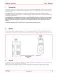
Overlander PEV
Power Wheelchair
Customer Manual
#8011
Uncontrolled Copy
Rev 7.0 Current 07/15/09
TABLE OF CONTENTS
DEFINITIONS OF SYMBOLS . . . . . . . . . . . . . . . . . . . . . . . . . . . . . . . . 1
INTRODUCTION
Description . . . . . . . . . . . . . . . . . . . . . . . . . . . . . . . . . . . . . . . 3
Specifications . . . . . . . . . . . . . . . . . . . . . . . . . . . . . . . . . . . . . . 4
PRE-USE INSPECTION AND SET UP
Safety Checklist . . . . . . . . . . . . . . . . . . . . . . . . . . . . . . . . . . . . . 5
Battery Installation and Removal . . . . . . . . . . . . . . . . . . . . . . . . . . . . 5
OPERATION OF MECHANISM
General . . . . . . . . . . . . . . . . . . . . . . . . . . . . . . . . . . . . . . . . . 8
Center of Balance . . . . . . . . . . . . . . . . . . . . . . . . . . . . . . . . . . . . 8
Curbs and Single Steps . . . . . . . . . . . . . . . . . . . . . . . . . . . . . . . . . 8
Doorways and Obstacles . . . . . . . . . . . . . . . . . . . . . . . . . . . . . . . . 9
Escalators . . . . . . . . . . . . . . . . . . . . . . . . . . . . . . . . . . . . . . . . 9
Motor Vehicle Safety . . . . . . . . . . . . . . . . . . . . . . . . . . . . . . . . . . 9
Reaching or Leaning . . . . . . . . . . . . . . . . . . . . . . . . . . . . . . . . . . 9
Slopes . . . . . . . . . . . . . . . . . . . . . . . . . . . . . . . . . . . . . . . . . 10
Street and Roadways . . . . . . . . . . . . . . . . . . . . . . . . . . . . . . . . . 11
Transfers . . . . . . . . . . . . . . . . . . . . . . . . . . . . . . . . . . . . . . . . 11
Transporting a Chair and Rider Up or Down Stairs . . . . . . . . . . . . . . . . . . 12
FEATURES
Anti-Tip Device . . . . . . . .
Armrest. . . . . . . . . . . .
Batteries . . . . . . . . . . .
Control System. . . . . . . .
Drive Motors . . . . . . . . .
Electric Wheel Lock Release.
Electrical Components . . . .
Footrest . . . . . . . . . . .
Manual Wheel Locks . . . . .
Pneumatic Tires . . . . . . .
Positioning Belts . . . . . . .
Upholstery Fabric . . . . . .
.
.
.
.
.
.
.
.
.
.
.
.
.
.
.
.
.
.
.
.
.
.
.
.
.
.
.
.
.
.
.
.
.
.
.
.
.
.
.
.
.
.
.
.
.
.
.
.
.
.
.
.
.
.
.
.
.
.
.
.
.
.
.
.
.
.
.
.
.
.
.
.
.
.
.
.
.
.
.
.
.
.
.
.
.
.
.
.
.
.
.
.
.
.
.
.
.
.
.
.
.
.
.
.
.
.
.
.
.
.
.
.
.
.
.
.
.
.
.
.
.
.
.
.
.
.
.
.
.
.
.
.
.
.
.
.
.
.
.
.
.
.
.
.
.
.
.
.
.
.
.
.
.
.
.
.
.
.
.
.
.
.
.
.
.
.
.
.
.
.
.
.
.
.
.
.
.
.
.
.
.
.
.
.
.
.
.
.
.
.
.
.
.
.
.
.
.
.
.
.
.
.
.
.
.
.
.
.
.
.
.
.
.
.
.
.
.
.
.
.
.
.
.
.
.
.
.
.
.
.
.
.
.
.
.
.
.
.
.
.
.
.
.
.
.
.
.
.
.
.
.
.
.
.
.
.
.
.
.
.
.
.
.
.
.
.
.
.
.
.
.
.
.
.
.
.
.
.
.
.
.
.
.
.
.
.
.
.
.
.
.
.
.
.
.
.
.
.
.
.
.
.
.
.
.
.
.
.
.
.
.
.
.
.
.
.
.
.
.
.
.
.
.
.
.
.
.
.
.
.
.
.
.
.
.
.
.
.
.
.
.
.
.
.
.
.
.
.
13
13
13
14
17
17
18
18
19
20
20
20
OPTIONS
Armrest. . . . . . . . . . . .
Elevating Footrest . . . . . .
Headrest . . . . . . . . . . .
Seating System Modifications
.
.
.
.
.
.
.
.
.
.
.
.
.
.
.
.
.
.
.
.
.
.
.
.
.
.
.
.
.
.
.
.
.
.
.
.
.
.
.
.
.
.
.
.
.
.
.
.
.
.
.
.
.
.
.
.
.
.
.
.
.
.
.
.
.
.
.
.
.
.
.
.
.
.
.
.
.
.
.
.
.
.
.
.
.
.
.
.
.
.
.
.
.
.
.
.
.
.
.
.
.
.
.
.
.
.
.
.
.
.
.
.
.
.
.
.
21
21
23
23
i
TABLE OF CONTENTS
SAFETY TIPS
Cleaning . . . . . . . . . . . . . .
Control System Care . . . . . . . .
Electromagnetic Interference (EMI)
Fasteners . . . . . . . . . . . . .
Maintenance . . . . . . . . . . . .
Storage . . . . . . . . . . . . . . .
.
.
.
.
.
.
.
.
.
.
.
.
.
.
.
.
.
.
.
.
.
.
.
.
.
.
.
.
.
.
.
.
.
.
.
.
.
.
.
.
.
.
.
.
.
.
.
.
.
.
.
.
.
.
.
.
.
.
.
.
.
.
.
.
.
.
.
.
.
.
.
.
.
.
.
.
.
.
.
.
.
.
.
.
.
.
.
.
.
.
.
.
.
.
.
.
.
.
.
.
.
.
.
.
.
.
.
.
.
.
.
.
.
.
.
.
.
.
.
.
.
.
.
.
.
.
.
.
.
.
.
.
.
.
.
.
.
.
.
.
.
.
.
.
.
.
.
.
.
.
.
.
.
.
.
.
24
24
24
26
26
27
WARRANTY INFORMATION
Limitations and Exclusions . . . . . . . . . . . . . . . . . . . . . . . . . . . . . . . 28
Governing Law . . . . . . . . . . . . . . . . . . . . . . . . . . . . . . . . . . . . . 28
Warranty Services Procedures. . . . . . . . . . . . . . . . . . . . . . . . . . . . . 29
MANUFACTURER DISCLAIMER
General Information . . . . . . . . . . . . . . . . . . . . . . . . . . . . . . . . . . 30
Trademarks and Patents . . . . . . . . . . . . . . . . . . . . . . . . . . . . . . . . 30
Copyright . . . . . . . . . . . . . . . . . . . . . . . . . . . . . . . . . . . . . . . . 30
ii
DEFINITIONS OF SYMBOLS
DEFINITIONS OF SYMBOLS
In the following sections you will find important instructions for your safety. The words
“WARNING” and “CAUTION” alert you to specific risk of personal injury or property damage.
They mean as follows:
WARNING
A hazard or unsafe practice that may cause severe injury or death
to you or to other persons.
CAUTION
A hazard or unsafe practice that may cause damage to this bed or
to other property.
Battery
Specification
Model
Information
Serial Number
MODEL
25061000 Overlander PEV Solid Seat
MANUFACTURE DATE
24VDC
BATTERY
ELECTRICAL RATING
DUTY CYCLE
WEIGHT CAPACITY
Int.
Indoor use only; Operate on flat surface.
MADE IN USA
Mode of
Operation
Date Manufactured
SERIAL NO.
Group 27 Gel 90 amp/hr
Access Restricted
XXXXXX
750 Cap.
MEDICAL ELECTRICAL
EQUIPMENT
Fuse
Specifications
1
ELLIS, KANSAS, USA
QS Doc. No. L-133, Rev. 1
Manufacture
Information
INTRODUCTION
You should make sure that persons who assist you read and follow all warnings and
instructions that apply to that use. Before using this powerchair, each attendant must know
what to do to ensure safety.
WARNING
If you fail to heed these warnings, severe injury may occur to you
or your attendant.
1. Put the user at ease. Tell the user what you plan to do and explain what you expect the
user to do.
2. Work with the user doctor, nurse or therapist to learn safe methods best suited to your
abilities and those of the user.
3. Always use good posture and proper body mechanics. When you lift or support the user,
bend your knees slightly and keep your back as upright and straight as you can.
DESCRIPTION
The Overlander PEV from Wheelchairs of Kansas offers dynamic performances for the
bariatric individual. It meets the mobility needs of the individual with rugged tires, a durable
steel frame for strength and the power of two 4-pole motors. The suspension is adjustable
allowing for fine-tuning of the individual rider. The gear belt drive system and 4-ply tires virtually
create an all terrain powerchairs. The PEV’s seating system can have a customized seating
system or a captain’s chair. The captain’s chair can not be customized and comes as is. The
customized seating system can individualized in the width, depth, and back height.
Flip Up
Armrests
Joystick
Adjustable
Headrest
Armrests
Joystick
Reclining
Back
Seat Belt
Elevating
Legrests
(optional)
Recline
Back Lever
Cradle
Footrests
Front
Wheels
Rear
Wheel
Rear
Wheel
Front
Wheels
2
INTRODUCTION
Right Motor Drive
Battery Box
Power
Module
Main
Frame
Drive Belt
Primary
Drive Belt
Sprocket
Rear
Shock
Manual
Wheel Lock
3
INTRODUCTION
SPECIFICATIONS
CUSTOMIZED SEATING SYSTEM
Overall Width - 18” - 24” . . . . . . . . . . . . . . . . . . . . . . . . . . . . 29.5”
24”. . . . . . . . . . . . . . . . . . . . . . . . . . . . . . . . . . 30”
26” . . . . . . . . . . . . . . . . . . . . . . . . . . . . . . . . 32.5”
28” . . . . . . . . . . . . . . . . . . . . . . . . . . . . . . . 34.75”
Overall Depth. . . . . . . . . . . . . . . . . . . . . . . . . . . . . . . . . . . . . . 35”
Overall Height - 19”-20” . . . . . . . . . . . . . . . . . . . . . . . . . . 19”-20”
21”-22” . . . . . . . . . . . . . . . . . . . . . . . . . . 21”-22”
Seat Depth . . . . . . . . . . . . . . . . . . . . . . . . . . . . . . . . . . . . 18”-24”
Seat Height - 19”-20” . . . . . . . . . . . . . . . . . . . . . . . . . . . . 19”-20”
21”-22” . . . . . . . . . . . . . . . . . . . . . . . . . . . . 21”-22”
Back Height. . . . . . . . . . . . . . . . . . . . . . . . . . . . . . . . . . . . 16”-24”
CAPTAIN’S CHAIR
Overall Width. . . . . . . . . . . . . . . . . . . . . . . . . . . . . . . . 28.5”-35.5”
DEPENDING ON ARMREST & JOYSTICK PLACEMENT
Overall Depth. . . . . . . . . . . . . . . . . . . . . . . . . . . . . . . . . . . . . . 35”
Overall Height - Floor to Top of Back . . . . . . . . . . . . . . . . . . . 41”
Floor to Top of Headrest . . . . . . . . . . . . . . . . 46”
Seat Width . . . . . . . . . . . . . . . . . . . . . . . . . . . . . . . . . . . . . . . . 25”
Seat Depth. . . . . . . . . . . . . . . . . . . . . . . . . . . . . . . . . . . . . . . . 21”
Seat Height from Floor . . . . . . . . . . . . . . . . . . . . . . . . . . . . . . 24”
Back Height - Back height. . . . . . . . . . . . . . . . . . . . . . . . . . . . 20”
Including Headrest . . . . . . . . . . . . . . . . . . . . 24.5”
Seat Thickness . . . . . . . . . . . . . . . . . . . . . . . . . . . . . . . . . . . . . 5”
Maximum Recline . . . . . . . . . . . . . . . . . . . . . . . . . . . . . . . . . . 40”
BOTH UNITS
Weight of Unit With Battery . . . . . . . . . . . . . . . . . . . . . . . . 385 lb.
Weight of Unit Without Battery. . . . . . . . . . . . . . . . . . . . . . 285 lb.
Battery Power . . . . . . . . . . . . . . . . . . . . . . . . . . 2 - Group 27 Gel
Battery Range. . . . . . . . . . . . . . . . . . . . . . . Varies (depending on
weight in chair & terrain)
Minimum Turning Radius. . . . . . . . . . . . . . . . . . . . . . . . . . . . . 41”
Maximum slope or incline . . . . . . . . . . . . . . . . . . . . . . 10 degrees
Weight Capacity . . . . . . . . . . . . . . . . . . . . . . . . . . . . . . . . . 750 lb.
(Exceeding this limit will void the warranty)
WARNING
If you fail to heed this warning, a fall may occur and cause severe
injury to you or your attendant, and may cause damage to this
wheelchair and to other property.
4
PRE-USE INSPECTION AND SETUP
SAFETY CHECKLIST
WARNING
If you fail to heed these warnings, severe injury may occur to you
or others. Before each use of your wheelchair you should:
1. Make sure all packing material is removed.
2. Check each connection to make sure all wires are secure after shipping.
3. Be sure batteries are fully charged before you operate the wheelchair.
4. Check that the anti-tip devices are not damaged. DO NOT OPERATE THIS WHEELCHAIR
WITHOUT THEM PROPERLY INSTALLED.
5. Install footrest/elevating legrests and armrests (including the joystick) before operating.
6. Make sure that your chair rolls easily and freely and that all parts work smoothly.
7. Check for excess noise, vibration or a change in ease of use. They may be signs of a
problem such as low tire pressure, loose fasteners or damage to the chair.
8. If you detect a problem, make sure to repair or adjust your chair before using it. Contact
your authorized Wheelchairs of Kansas dealer to help you find and correct the problem.
BATTERY INSTALLATION & REMOVAL
WARNINGS
If you fail to heed these warnings, improper installation may
cause personal injury or property damage if instructions are not
followed.
Tools Required:
5/8” Wrench
7/16” Wrench
To Module
Power Cable
WHEEL
#
#
1
Fuse
Holder
2
REAR OF CHAIR
TOP VIEW
5
WHEEL
To install the batteries in the PEV, follow
these steps in order. To remove the
batteries, follow these steps in reverse
order. If you have any questions regarding
these instructions, please contact 800-5376454.
PRE-USE INSPECTION AND SETUP
1. At the rear of the chair, there are two
shocks. Remove the top bolts on both
shocks, with a 5/8” wrench.
2. Undo velcro that is holding the top of the
battery box on.
3. Lift seating system up. The front of the seating system
will remain attached.
4. Disconnect wiring harness from the control
module.
6
PRE-USE INSPECTION AND SETUP
5. Remove battery box top.
6. With a 7/16“ wrench disconnect the black
(negative) wire and the red (positive) wire
from each of the batteries on the left side.
WARNING
Electric Shock
Hazard. Do not let
wires cross.
7. With a 7/16“ wrench disconnect the red
(positive) wire and the black (negative)
wire from each of the batteries on the
right side.
WARNING
Electric Shock
Hazard. Do not let
wires cross.
8. Remove Batteries.
WARNING
Each battery weighs
approximately 60 lbs.
Place hardware in battery box and replace
battery box lid for transport. Reattach
velcro that is holding the top of the battery
box on.
7
OPERATION OF MECHANISM
GENERAL
WARNING
If you fail to heed these warnings, a fall or tip over may occur and
cause severe injury to you:
1. Start off slowly. If you are not familiar with the maneuverability of this wheelchair you may
loose control and tip over.
2. Have someone help you until you know what can cause a tip over and how to avoid doing
so. Never try a new maneuver on your own until you are sure you can do it safely.
3. Your chair is most stable when you are moving forward. Be very careful when you move
your wheelchair backward. You may lose control or tip over if one of the rear wheels hits an
object and stops rolling.
CENTER OF BALANCE
WARNINGS
The point where the chair will tip forward, rearward or to the side
depends on its center of balance and stability. If you fail to heed
these warnings, a fall or tip over may occur and cause severe
injury to you.
1. To avoid a fall or tip over, you should have someone help you until you know the balance
points of your chair and how to avoid a tip over.
2. The center of balance and stability of your chair are affected by :
A. A shift in your body position, posture or weight distribution.
B. Riding your chair on a sloped surface.
CURBS AND SINGLE STEPS
WARNINGS
If you fail to heed these warnings, a fall or tip over may occur and
cause severe injury to you or others:
1. The anti-tip devices are not removable and may interfere.
2. Do not try to climb or descend a curb or a step, more than 1 1/2 inches high. Whenever
possible, seek a suitable ramp or access designed for electric wheelchairs.
CAUTION
The impact from dropping down from a curb or step can damage
the frame or other chair parts and may loosen fasteners. Check for
damage to the wheelchair or loose fasteners before each use.
8
OPERATION OF MECHANISM
DOORWAYS AND OBSTACLES
1. Make sure that the floor area where you use this chair is level and free of obstacles. You
may need to:
A. Remove or cover threshold strips between doors.
B. Install a ramp at some doors.
2. To help correct the center of balance of your wheelchair you should:
A. Lean your upper body forward slightly as you go up over an obstacle.
B. Press your upper body backward as you go down from a higher to a lower level.
ESCALATORS
WARNING
Never take a chair on an escalator, even with an attendant. Doing
so is likely to cause a fall or tip over and severe injury to you and
others.
MOTOR VEHICLE SAFETY
WARNING
Wheelchairs of Kansas wheelchairs do not meet the federal
standards for motor vehicle seating. If you fail to heed these
warnings, the rider may suffer a severe injury:
1. Never permit anyone to sit in this wheelchair while he or she is in a moving vehicle. The
rider may be thrown from the chair in an accident or sudden stop. Wheelchair positioning
belts will not prevent this.
2. Always move the rider to an approved vehicle seat. Secure the rider with proper motor
vehicle restraints.
3. Never transport this chair in the front seat of a vehicle. It may shift and interfere with the
driver. Always secure this chair so that it cannot roll or shift.
REACHING OR LEANING
(Example: Dressing or Changing Clothes)
WARNINGS
Reaching or leaning affects the center of balance of your
wheelchair. If you fail to heed these warnings, a fall or tip over may
occur and cause severe injury to you:
9
OPERATION OF MECHANISM
1. Avoid reaching or leaning if you must shift your weight to do so. Ask for help or use a
device to extend your reach.
2. Never try to reach an object if you must move forward in your seat to do so. This may
cause the wheelchair to tip forward. Always keep your buttocks in contact with the
backrest.
3. Never reach with both hands. If you do so, you may not be able
to catch yourself to prevent a fall if the chair tips.
4. Never lean backward to reach an object.
5. If you must reach or lean from your chair:
A. Place your chair as close as you can to the object you wish to
reach.
B. Avoid putting pressure on the footrests/elevating legrests
while you reach. This may cause the chair to tip forward.
Put Front Casters
in Position Shown
SLOPES
WARNINGS
Going up or down a slope will change the center of balance of your
chair. If you fail to heed these warnings, you may suffer a severe
injury from a tip over, fall or lose of control:
1. Lean or press your body uphill to help correct the change in the center of balance.
2. Avoid turning on a slope, as a tip over is likely. Always go as straight up and straight down
as you can.
3. The power drive mechanism WAS NOT designed to climb a slope and/or incline greater
than 10 degrees. (A 10% slope means: One foot of elevation for every ten feet in length of
the slope.) Ask for help if the slope is greater than 10 degrees.
4. Controlling speed when going downhill:
A. The power drive mechanism was designed to maintain a safe speed while going down a
10 degree or less slope. Ask for help if the slope is greater than 10 degrees.
B. Never use the rear wheel locks to try to slow or stop your wheelchair. Doing so is likely
to cause you to veer out of control or tip over.
10
OPERATION OF MECHANISM
STREETS AND ROADWAYS
WARNINGS
In most states, wheelchairs are not legal for use on public roads. Be
alert to the dangers of motor vehicle traffic on roads or in parking
lots.
1. At night, or when lighting is poor, use reflective tape on your wheelchair and clothing to
make it easier for drivers to see you.
2. Due to low position, it may be hard for drivers to see you. Make eye contact with drivers
before you go forward. When in doubt, yield until you are sure it is safe.
TRANSFERS
WARNINGS
If you fail to heed these warnings, a fall or tip over may occur and
cause severe injury to you:
1. Transfers require good balance and agility and are very dangerous. Be aware that there is
a point during each transfer when the chair seat is not below you.
2. Always lock the rear wheels before you transfer.
3. Locking the rear wheels will not keep your chair from sliding away from you or tipping. To
avoid a fall, you should:
A. Learn how to position your body and how to support yourself during a transfer.
B. Work with your doctor, nurse or therapist to learn safe transfer methods.
C. Have someone help you until you are sure you can perform
safe transfers on your own.
4. Rotate the front casters into position show to make the chair
more stable.
5. Be careful of the footrests. To avoid a trip or fall when you
transfer, you should:
A. Make sure your feet do not “hang up” or get caught in the
space between the footrests.
B. Avoid putting weight on the footrests as the chair may tip
forwards.
C. If you can, remove or swing the footrests out of the way.
Put Front Casters
in Position Shown
6. Removing armrest may be helpful.
11
OPERATION OF MECHANISM
TRANSPORTING A CHAIR AND RIDER UP OR DOWN STAIRS
WARNING
Wheelchairs of Kansas does not endorse or recommend the lifting
of the chair, with a person in it. Other means of transport must be
used to carry a person over stairs or obstructions in the pathway if
no ramp or other means is provided to properly roll the chair
around or over the stairs or obstructions.
12
FEATURES
ANTI-TIP DEVICE
WARNING
The anti-tip devices are not designed to bear the weight of the
wheelchair and rider. Failure to heed this warning when climbing or
descending stairs, curbs, steps or other objects could result in
damage to the wheelchair and cause the wheelchair to tip or fall
causing severe injury to you or others.
ARMREST
The armrests are detachable. They are not designed to bear the weight of the wheelchair.
WARNING
Never try to lift the wheelchair by its armrest. They may come loose
or break. If this occurs, the wheelchair may fall and cause severe
injury to you or others. Lift the wheelchair only by non-detachable
parts of the main frame.
BATTERIES
Never tamper with the batteries on this wheelchair.
WARNING
The type of batteries used on this wheelchair contain a highly
corrosive acid. Never let the acid come in contact with yourself or
any other object. If you fail to heed these warnings, you may suffer
severe burns or other injury and/or cause damage to anything that
comes into contact with the acid.
If the batteries become damaged, contact your authorized
Wheelchairs of Kansas dealer immediately for replacement. Always
read and follow battery manufacturer’s directions.
Your PEV Powerchair could have either Gel batteries (sealed) or Lead Acid. You and your
dealer, once having assessed your intended use of the powerchair, should make this choice.
The primary difference between the two types are, lead acid holds approximately 20% more
charge so they can go longer between charges. Lead acid can also be recharged in twice the
time of a sealed battery. Lead acid batteries require periodic maintenance. If tipped over they
can leak acid and need special handling if being transported by an airline.
Do not rely on the battery charger to tell whether or not the batteries are fully charged. Do not
rely on the voltage indicator on the joystick to tell whether or not the batteries have been fully
charged, or if the batteries can maintain a charge. Periodic inspection needs to be done with
the proper test equipment and trained service personnel. It is normal for batteries to gradually
wear down and require longer charging times. See maintenance section for additional care
instructions of battery.
13
FEATURES
CHARGING THE BATTERY:
Connect the charger to the bottom side of the joystick, then
connect to the wall outlet. Always connect the charger to the
powerchair first, then connect to the wall outlet.
Always keep your powerchair fully charged. Connect the
batteries to a charger every night and then disconnect them in
the morning. A charging pattern of 12 to 14 hours on a charger
and 12 to 14 hours off a charger will help to maintain strong fully
charged batteries.
When charging Gel or sealed batteries, do not exceed a 8-amp charge rate. Doing so runs the
risk of irreversible damage to the battery by causing it to split open or burst. The proper
charger is shipped with the powerchair.
When charging lead acid batteries do not exceed a 12-amp charge rate. Doing so runs the risk
of prematurely wearing out the batteries.
When charging is complete, disconnect the charger from the wall outlet first, then from the
powerchair. Always disconnect the charger from the wall outlet first, then from the powerchair.
CONTROL SYSTEM
The information in this manual is a brief overview. See the VR2 Control System Manual for
more details.
WARNING
The manufacturer of the VR2 and Wheelchairs of Kansas accepts no
liability for losses of any kind arising from unexpected stopping of
the powerchair or improper programming of the control system,
improper use of the powerchair, improper use of the control system
or if any of the criteria detailed in this document are not met.
The internal settings for the joystick and control module are preset at the factory for your safety
to insure proper power and operation of the wheelchair. Do not change any programmed
functions without authorization from Wheelchairs of Kansas. To do so will void any and
all warranties.
Joystick: This controls the speed and direction of the wheelchair. Push the joystick in the
direction you wish to go. The further you push it, the faster the speed. Releasing the joystick
stops the wheelchair and automatically applies the brakes.
Charger and programmer Socket: Only connect a PGDT Programmer or the charger
supplied with the wheelchair into this socket. The charger current must not exceed 12 Amps
14
FEATURES
and the charger must be fitted with a Neutrik NC3MX plug. This socket must not be used as a
power supply for any other electrical device.
Power Module and Joystick Cable: The Power Module contains most of the electronics for
controlling the wheelchair. It has three main connections to the batteries and each motor. The
Joystick Cable links the Power Module to the Joystick Module. For further information refer to
the wheelchair manufacturer’s documentation.
Battery Gauge: This is a 10 segment display
which indicates if the VR2 is switched on and gives
the state of charge of the battery. Additionally, any
faults in the wheelchair’s electrical system are
indicated by this display. Refer to the wheelchair’s
documentation for more details.
On/Off Button: This button
turns the VR2 on and off.
Do not use this button to
stop the wheelchair, except
in an emergency.
Horn Button: This button
operates the wheelchair’s
horn.
Maximum Speed / Profile
Indicator: This is a 5
segment display which
indicates the maximum
speed setting or which
drive profile is selected.
The wheelchair’s
documentation will state
whether the VR2 is set up
for maximum speed or
drive profile operation.
Speed/Profile Increase
Button: This button
increases the maximum
speed setting or selects a
higher drive profile.
Speed/Profile Decrease
Button: This button
decreases the maximum
speed setting or selects a
lower drive profile.
Actuator button and LED: If the wheelchair is fitted with
actuators, this button(s) will enter and exit actuator
adjustment mode. When in actuator adjustment mode,
the LED will be illuminated.
Daily Checks
Joystick: With the control system switched off, check that the joystick is not bent or damaged
and that it returns to center when you release it. If there is a problem do not use your
wheelchair and contact your dealer.
15
FEATURES
Cables: Check condition of all cables for damage.
Joystick Gaiter: Check the thin rubber gaiter around the base of the joystick for damage or
splitting. Check visually only, do not handle the gaiter.
Mounting: Make sure the controller is securely fixed to your wheelchair. Do not over tighten
any screws.
Weekly Checks
Electrical Brakes:
This test should be carried out on a level floor with at least one meter
clear space around the wheelchair.
Check that after 1 second the battery gauge remains on or flashes slowly.
Push the joystick slowly forwards until you hear the electrical brakes
operate. The chair may start to move.
Immediately release the joystick, you must be able to hear each electrical
brake operate within a few seconds.
Repeat the test three times, pushing the joystick backwards, lift and right
respectively.
If your wheelchair is fitted with lights, turn indicators or seat adjustment
actuator, checks the operation of these.
Precautions For Use
The VR2 control system has been designed with the user’s safety as the prime consideration.
It incorporates many sophisticated self-test features which search for potential problems at a
cycle of 100 times per second. If the control system detects a problem either in its own circuits,
or in the wheelchair’s electrical system, it may decide to halt the wheelchair depending on the
severity of the problem. The VR2 is designed to maximize the user’s safety under all normal
conditions.
In spite of its sophistication, the VR2 cannot take into account circumstances which put the
wheelchair and/or the controller outside of their specified operation conditions, and so it is
important that the user follows the precautions below:
1. Do not drive the wheelchair:
A. Beyond restrictions indicated in the wheelchair user manual, for example maximum
inclines, curb height etc.
16
FEATURES
B. In places or on surfaces where a loss of wheel grip could be hazardous, for example on
wet grassy slopes.
C. If the controller of other crucial components are known to require repair. In the event of
the wheelchair moving in an unexpected way RELEASE THE JOYSTICK. This action
will stop the wheelchair under any circumstances.
2. Although the VR2 control system is designed and manufactured to be extremely reliable
and each unit is rigorously tested, a system malfunction is always a possibility (however
with a small probability). Under some conditions the system may detect a malfunction, the
controller will (for safety reasons) stop the chair instantaneously. If the physical impairments
of the user are such that a sudden braking action could result in a fall from the chair, it is
imperative that a restraining device such as a seat belt be purchased and installed with the
chair. Restraining devices should be used at all times when the wheelchair is in motion.
DRIVE MOTORS
Note: The motors are equipped with an internal parking brake.
The PEV incorporates two 4-pole 24 VDC, high torque motors with automatic braking and
manual release. The brakes engage within two seconds of the joystick being placed in the
neutral position. The brakes will release immediately when the joystick is moved in any
direction.
When the power on the wheelchair is turned off (the controller turned off), the electric lock
brakes can be released manually by moving the release lever on the front of the chair. When
lever is in this position the chair is able to move freely without the use of the motors. As a
safety precaution, the wheelchair will not operate when the brake is being held in the
manual release position.
ELECTRIC WHEEL LOCK RELEASE
Move the lever to the left (when facing) to
disengage and right (when facing) to engage.
17
FEATURES
ELECTRICAL COMPONENTS
Never allow the electrical components to become wet.
WARNING
The electrical components of this wheelchair are not designed to be
moisture proof. If you allow these components to become wet, you
could suffer an electrical shock and/or cause severe damage to the
components.
FOOTRESTS
The footrests are detachable. They are not designed to bear the weight of this wheelchair.
WARNING
Never try to lift the wheelchair by its footrests/elevating legrest.
They may come loose or break. If this occurs, the wheelchair may
fall and cause severe injury to you or others. Lift the wheelchair
only by parts that do not detach from the main frame.
If you fail to heed these warnings, a fall or tip over may occur and cause severe injury to you:
The lowest point of the footrests should be at least 2-1/2 inches above the ground level on a
flat surface. If set too low, they may “hang up” on the types of obstacles you can expect to find
in normal use. This may cause the wheelchair to stop suddenly and tip forward. To Remove:
1. Pull up on the pin located at the top of the
footrest.
2. Using your other hand, swing the footrest outward. Pull
down pin and continue to pull out the footrest.
18
FEATURES
To Adjust Height:
Remove the two bolts located near the
bottom of the footrest. Slide the footrest
up or down to the desired height, then
replace the two bolts in the correct
aligning holes.
MANUAL WHEEL LOCKS
WARNING
The chair will not operate with manual wheel locks engaged. The
manual wheel locks are independent of the electric wheel locks, the
Overlander also has on each wheel an additional manual locking
mechanism. This system locks up the actual drive at the rear wheel
hub and so works regardless of tire condition for greater safety.
Manual wheel locks are not designed to slow or stop a moving
wheelchair. Use them only to keep the rear wheels from turning
when the chair is at a complete stop (such as, during transport). If
you fail to heed this warning, you may suffer a severe injury from a
tip over, fall or loss of control. For safety purpose, disengage
electric wheel lock when engaging manual wheel locks. The manual
wheel locks are accessed at the rear of the wheelchair.
When engaging the manual wheel locks, be
sure to lock both sides. The locks are located
on the inside of each rear tire.
To engage the manual wheel lock, pull down
the black lever located to the inside of each
tire. This locks up the actual drive at the rear
wheel hub, so it works regardless of tire
condition.
19
FEATURES
PNEUMATIC TIRES
Proper inflation extends the life of your tires and makes your wheelchair easier to operate.
1. Do not use this wheelchair if any of the tires are under or over inflated. Check weekly for
proper inflation level, as listed on the tire sidewall.
2. Low pressure in any of the tires may cause the chair to veer to one side and may result in
loss of control.
3. Over inflated tires may burst.
POSITIONING BELTS
Use positioning belts only to help support the rider’s posture.
WARNING
Improper use of positioning belts may cause severe injury or death
of the rider.
1. Make sure that the rider does not slide down in the wheelchair seat. If this occurs, the rider
may suffer chest compression or suffocate due to pressure from the belts.
2. The belts must be snug, but must not be so tight that they interfere with breathing. You
should be able to slide your open hand, flat, between the belt and the rider.
3. A pelvic wedge or similar device can help the rider from sliding down in the seat. Consult
with the rider’s doctor, nurse or therapist to find out if the rider needs such a device.
4. Use positioning belts only with a cooperative rider. Make sure that the rider can easily
remove the belts in an emergency.
5. Never use positioning belts:
A. As a patient restraint. A restraint requires a doctor’s order.
B. On a rider who is comatose or agitate.
UPHOLSTERY FABRIC
WARNING
Replace worn or torn fabric immediately. Failure to do so may result
in a fall and severe injury to you.
The standard upholstery features a breathable 100% nylon fabric. The material is urethane
coated for water resistance. The nylon fabric consists of 210 Denier which is soft, with low
shear properties. The upholstery makeup provides durability for our products.
20
OPTIONS
ARMREST
The armrests are detachable. They are not designed to bear the weight of the wheelchair.
WARNING
Never try to lift the wheelchair by its armrest. They may come
loose or break. If this occurs, the wheelchair may fall and cause
severe injury to you or others. Lift the wheelchair only by nondetachable parts of the main frame.
Adjustable height armrests are optional. To
adjust the height, hold down the pin located
on the inner part of the armrest. Pull the
armrest up to the desired height, then
release the pin back into the aligning hole
of the armrest.
ELEVATING LEGRESTS
The legrests are detachable. They are not designed to bear the weight of this wheelchair.
WARNING
Never try to lift the wheelchair by its elevating legrest. They may
come loose or break. If this occurs, the wheelchair may fall and
cause severe injury to you or others. Lift the wheelchair only by
parts that do not detach from the main frame.
If you fail to heed these warnings, a fall or tip over may occur and cause severe injury to you:
The lowest point of the legrest should be at least 2-1/2 inches above the ground level on a flat
surface. If set too low, they may “hang up” on the types of obstacles you can expect to find in
normal use. This may cause the wheelchair to stop suddenly and tip forward.
To Remove:
1. Pull up on the pin located at the top of the
legrest.
21
OPTIONS
2. Using your other hand, swing the legrest
outward. Pull down pin and continue to pull
out the legrest.
To Adjust Height:
Remove the two bolts located near the
bottom of the footrest. Slide the
footrest up or down to the desired
height, then replace the two bolts in
the correct aligning holes.
To Elevate:
Pull out the pin located on the underside
of the legrest. With your other hand, move
the legrest up or down to one of the five
height settings. Return the pin into the
new aligning holes.
22
OPTIONS
HEADREST
Adjustable Headrest
Height Adjustment:
1. Loosen bottom knob on back of headrest and slide
the headrest to the desired position.
2. Tighten the knob.
Depth Adjustment:
1. Loosen top knob on back of headrest and slide the
headrest to the desired position.
2. Tighten the knob.
10” Headrest Extension
To Remove or Install:
1. Pull pins 2-places and pull headrest up to
remove.
2. Reverse order to install.
SEATING SYSTEM MODIFICATIONS
WARNING
Use of a seating system not approved by Wheelchairs of Kansas
may alter the center of balance of the wheelchair. This may cause
the wheelchair to tip over and result in severe injury to you. Do not
make a change to the seating system of your wheelchair unless
you consult your authorized Wheelchairs of Kansas dealer first.
23
SAFETY TIPS
CLEANING
Periodic cleaning of the frame and upholstery is recommended. Hand wash with a nonabrasive cleaner and drip dry or wipe dry with a soft cloth. Do not put upholstery in a dryer.
The frame may be polished with a non-abrasive automotive wax.
Do not get electrical components wet.
CONTROL SYSTEM CARE
Avoid knocking your control system, especially the joystick.
When transporting your wheelchair ensure the control system is well protected.
To prolong the life of the control system, keep exposure to extreme conditions to a minimum.
Always clean your control system if it becomes contaminated with food or drink.
Use a damp cloth and washing with liquid mixed with water. Do not use abrasive or spirit
based cleaning agents.
ELECTROMAGNETIC INTERFERENCE (EMI)
WARNING
Radio wave sources, such as radio stations, TV stations, amateur
radio (HAM) transmitters, two-way radios, and cellular phones, can
affect powered wheelchairs. Following the warnings listed below
should reduce the chance of unintended brake release or powered
wheelchair movement which could result in serious injury.
1. Do not turn ON hand-held personal communication devices, such as citizens band (CB)
radios and cellular phones while the powered wheelchair is turned ON.
2. Be aware of nearby transmitters, such as radio or TV stations, and try to avoid coming close
to them.
3. If unintended movement or brake release occurs, turn the powered wheelchair OFF as soon
as it is safe.
4. Be aware that adding accessories or components, or modifying the powered wheelchair,
may make it more susceptible to interference from radio wave sources (Note: There is no
easy way to evaluate their effect on the overall immunity of the powered wheelchair).
5. Report all incidences of unintended movement or brake release to the powered wheelchair
manufacturer, and note whether there is a radio wave source nearby.
24
SAFETY TIPS
Important Information
The EMI value of this device was tested to 20 volts per meter (V/m), although if any
accessories are added the immunity level is unknown. (EUT tested February 2001)
CAUTION
IT IS VERY IMPORTANT THAT YOU READ THIS INFORMATION
REGARDING THE POSSIBLE EFFECTS OF ELECTROMAGNETIC
INTERFERENCE ON YOUR POWERED WHEELCHAIR.
Electromagnetic Interference (EMI) From Radio Wave Sources
Powered wheelchairs may be susceptible to electromagnetic interference (EMI), which is
interfering electromagnetic energy (EMI) emitted from sources such as radio stations, TV
stations, amateur radio (HAM) transmitters, two-way radios, and cellular phones. The
interference (from radio wave sources) can cause the powered wheelchair to release its
brakes, move by itself, or move in unintended directions. It can also permanently damage the
powered wheelchair’s control system. The intensity of the interfering EMI energy can be
measured in volts per meter (V/m). Each powered wheelchair can resist EMI up to a certain
intensity. This is called its “immunity level”. The higher the immunity level, the greater the
protection. At this time, current technology is capable of achieving at least a 20 V/m immunity
level, which would provide useful protection from the more common sources of radiated EMI.
This powered wheelchair model as shipped, with no further modification. The immunity level of
this product is not known.
There are a number of sources of relatively intense electromagnetic fields in the everyday
environment. Some of these sources are obvious and easy to avoid. Others are not apparent
and exposure is unavoidable. However, we believe that by following the warnings listed below,
your risk to EMI will be minimized. The sources of radiated EMI can be broadly classified into
three types:
1. Hand-held portable transceivers (transmitters-receivers) with the antenna mounted directly
on the transmitting unit. Examples include citizens band (CB) radios, “walkie talkies”,
security, fire, and police transceivers, cellular telephones and other personal
communication devices.
NOTE: Some cellular telephones and similar devices transmit signals while they are ON,
even when not being used.
2. Medium-range mobile transceivers, such as those used in police cars, fire trucks,
ambulances, and taxis. These usually have the antenna mounted on the outside of the
vehicle.
3. Long-range transmitters and transceivers, such as commercial broadcast transmitters
(radio and TV broadcast antenna towers) and amateur (HAM) radios.
NOTE: Other types of hand-held devices, such as cordless phones, laptop computers,
AM/FM radios, TV sets, CD players and cassette players, and small appliances, such as
electric shavers and hair dryers, so far as we know, are not likely to cause EMI problems to
your powered wheelchair.
25
SAFETY TIPS
FASTENERS
WARNINGS
Many of the screws and bolts used in your wheelchair are special
high-strength fasteners. If you fail to heed these warnings, a fall
may occur and cause severe injury to you:
1. Improper fasteners may fail. Use only screws and bolts provided by an authorized
Wheelchairs of Kansas dealer.
2. If screws or bolts become loose, tighten them as soon as possible.
MAINTENANCE
WARNING
Your wheelchair requires regular maintenance to maintain
performance and avoid premature wear, damage and injury.
You should check the items on this chart at the indicated intervals. If any or the items are
loose, worn, bent or distorted, immediately have them checked and/or repaired by your
authorized Wheelchairs of Kansas dealer. Frequent maintenance and servicing will improve
performance and extend wheelchair life.
Three Months
Six Months
Annually
Armrest
Drive Train
Fasteners
Frame
Upholstery
Wheels & Tires
Wheels Locks
Electrical Components
Batteries
Headrest
Legrest
Dealer Inspection
Batteries may take additional maintenance, such as visual inspection every three months.
When inspecting batteries look for any corrosion, leaking or bulging. Batteries should be
replaced after 18 months or sooner, depending on the care and usage.
26
SAFETY TIPS
The battery may require recycling in accordance with local laws. Contact you local recycling
center for proper battery disposal or local regulatory authorities for more information.
WARNING
Never dispose of batteries in a fire because they may explode.
TIRE PRESSURE
Check weekly for proper inflation level, as listed on the tire side wall.
STORAGE
Your wheelchair should be stored in a dry location so that the components do not rust. If your
wheelchair is stored for any period of time, remove the batteries and charge them once a
week. When bringing the wheelchair back into use after storage make sure it is adjusted
properly and that all components are in working order before operating.
27
WARRANTY INFORMATION
PRODUCT
Overlander/PEV
WEIGHT
CAPACITY
750 lbs.
WARRANTY
Five year warranty on frame; One year on all other
components.
LIMITATIONS AND EXCLUSIONS
1. Products which have been used for purposes other than the intended uses; or which have
been subject to negligence, abuse, improper storage or handling, improper operation,
unauthorized modifications or damages beyond normal wear and tear as determined by
Wheelchairs of Kansas are not covered by this warranty.
2. If weight capacity on any such product is exceeded, the warranty will be void. Any
unauthorized repairs to product/part, as well as tampering with any components, will void
the warranty.
3. Parts or materials which are subject to normal wear resulting from the use of these
products and which must be replaced/repaired due to such normal wear, are the owner’s
responsibility and are not covered by this warranty.
4. This warranty is exclusive and in lieu of all other express warranties, implied warranties,
including but not limited to the implied warranty of merchantability and fitness for a
particular purpose, and shall not extend beyond the duration of this warranty. Wheelchairs
of Kansas shall not be liable for any consequential or incidental damages whatsoever.
5. This warranty applies to the purchaser only and is non-transferable. Invoice/shipping date
is used as the start date for the warranty.
6. For warranty information in Canada please contact Canadian Medical Healthcare at 1-877850-1330.
GOVERNING LAW
This purchase order and warranty shall be deemed executed in the county of Ellis, state of
Kansas and the point of sale shall be deemed to be in the county of Ellis, state of Kansas. All
disputes relating hereto shall be exclusively governed by, and construed in accordance with,
the laws of the State of Kansas, without reference to its conflict of laws principles. Any legal
action or proceeding relating to this purchase shall be instituted solely in a state of federal
court in Ellis County, Kansas. Wheelchairs of Kansas and customer agree to submit to the
jurisdiction of, and agree that venue is proper in, these courts in any such legal action or
proceeding.
28
WARRANTY INFORMATION
WARRANTY SERVICES PROCEDURES
1. The product/part should be returned to the original selling dealer. To return the product/part
to the factory the dealer must call to request authorization. At this time a return
authorization number (RA#) will be issued. This RA# will be valid for 21 days from date
issued. If the product/part is shipped to the factory without a RA # it will be refused.
2. Wheelchairs of Kansas products, with the exception of the bath/shower aids, are identified
by a 6-digit serial number. Serial number identification is required for discussion of service.
Removal or defacing this serial number may void all warranty.
3. For headboards and footboards with the beds, which are not covered under warranty, the
customer will be responsible for shipping and return shipping costs. For all other products
and parts, customers will not be responsible for shipping or return shipping costs for
products and parts under this warranty returned within thirty (30) days of receipt; 31 - 60
days, customer will be responsible for shipping costs to Wheelchairs of Kansas; 61 days or
more, customer will be responsible for shipping and return shipping costs.
4. If the problem is a result of defective material or workmanship, the product/part will be
replaced or repaired at the discretion of Wheelchairs of Kansas, at no charge to the
customer.
5. For replacement or repair of a product/part not covered under this warranty or if warranty is
void the following applies: labor charges (minimum of $45/hour; minimum of 1 hour)
incurred and freight or delivery charges will be billed to the customer.
NOTE: Wheelchairs of Kansas will only pay regular ground freight on warranty product/parts.
29
MANUFACTURER DISCLAIMER
GENERAL INFORMATION
All specifications, equipment and prices are subject to change without notice. Wheelchairs of
Kansas reserves the right to make improvements from time to time. Photos and drawings are
representative of the products and may vary slightly from actual production models. Some
items photographed in this brochure may include optional equipment. Contact or consult with
your dealer to ensure proper equipment sizes, specifications and options.
Distributor is responsible for translation of this manual.
TRADEMARKS AND PATENTS
BCW and Wheelchairs of Kansas are registered trademarks of Raye’s Inc.
COPYRIGHT
Copyright © 2004 by Raye’s Inc.
dba Wheelchairs of Kansas
All rights reserved.
No part of the contents of this book may be reproduced, stored in a retrieval system or
transmitted in any form or by any means, electronic, mechanical, photocopying, recording or
otherwise, without the written permission of Raye’s Inc.
30
800-537-6454
785-726-4885
www.wheelchairsofkansas.com