1
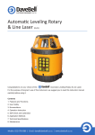
Electronic Auto-level
Rotating Laser
(RL400)
Congratulations on your choice of this
electronic auto-level rotating laser. For the
purpose of long-term use of this instrument, we suggest you to read this instruction manual carefully
before using it.
Contents
1. Features and Functions
2. Laser Safety
3. Nomenclature
4. Operation Instruction
5. Application Methods
6. Application Demonstration
7. Self-Check and Calibration
8. Technical Specifications
9. Packing List
10. Maintenance
1. Features
• Output the laser-new function, It extends the usage and survey range.
• Large electronic auto-level range. When beyond the range, laser blinks, and terminate rotation to
ensure the measurement.
•“Vertical”&”horizontal” two working modes,respectively able to project one laser horizontal plane and
one plumb line, and one plumb plane and one horizontal line.
• Able to adjust the laser rotating scan speed
• Scan function to adjust the scan angle and scan direction
• Slope operation function facilitates user to perform the slope scan at different inclinations.
• Calibration function
• Rainproof, dustproof and shockproof
• Timing auto-off function
• Optional detector and remote control will bring more convenient operations.
• Various accessories of elaborate design would expand instrument’s application range.
2. Laser Safety
• Laser output mark is attached beside the output aperture
• Do not look straight at the laser beam.
• Do not disassemble the instrument or attempt to perform any internal servicing. Repairs and
orm
anyinternal
internalservicing.
servicing.Repairs
Repairsand
and
rm any
servicing are to be performed only by authorized service centers.
ng
aretotobe
beperformed
performedonly
onlyby
by
g are
•
This
instrument
complies
with
the safety classification standards of laser radiation.
zedservice
servicecenters.
centers.
zed
strument
complieswith
withthe
thesafety
safety
trument complies
cation
cation
rds
of
ds of
adiation.
diation.
menclature
menclature
Verticallaser
laseroutput
outputwindow
window
Vertical
Rotatinglaser
laseroutput
outputwindow
window
Rotating
Handle
Handle
This instrument complies with the safety
classification
standards of
laser radiation.
3.Nomenclature
3. Nomenclature
Vertical laser output window
Rotating laser output window
Handle
Operation panel
4.Operation Instruction
Battery:
LS521II is equipped with one battery case for both
Battery cover DC 6v 5 plug
Ni-MH pile.
1.Ni-MH pile:
4. Operation Instruction
Using coin to unscrew the battery cover to open it.
Battery:
3
As
fig.
respectively
insert
the two rechargeable
LS521II is equipped with one battery case for both Ni-MH pile.
batteries into the battery case (note: inserting the
1.Ni-MH pile:
battery pack, the convex lead-line of the battery
• Using coin to unscrew the battery cover to open it. As fig. respectively insert the two rechargeable
pack
matches
with
thetheconcave
in the
battery
batteries into
the battery
case (note:
inserting
battery pack,slot
the convex
lead-line
of the battery
case.)
insert
thebattery
lead-line
jack beside
pack matches
with theand
concave
slot in the
case.) andinto
insertthe
the lead-line
into the jack beside
the
battery
pack.
Finally
screw
the
battery
case
the battery pack. Finally screw the battery case using coin. Turn on, the unit works normally.
using coin. Turn on, the unit works normally.
Concave slot of battery case
By using the special adapter, charge the pack
though external outlet jack. Now the charging
indicator lamp displays red, and after 5 hours
• By using the special adapter, charge the pack though external outlet jack. Now the charging indicator
lamp displays red, and after 5 hours or so, lamp will become green, which means the Ni-MH pile has
been fully charged.
Note : ( 1) We suggest you charge the pack for two more hours after completely charged to ensure its
capacity.
2.C Alkaline battery
Take out the special Ni-MH pack, put in 4 C
(3) The unit can still work, when charged with adapter.
alkaline battery according to the illustrated
polarity direction. Finally screw the battery
2.C Alkaline battery
cover using a coin. Press the ON key, the unit
2.Cout
Alkaline
battery
Take
the special
Ni-MH pack, put in 4 C There
alkaline battery
according to the illustrated polarity
Take out the works
special normally.
Ni-MH pack, put in is
4 no
C charging indicator
direction.
Finally
screw
the
battery
cover
using
a coin. Presswith
the ONthe
key,adapter.
the unit works normally.
lamp,
although
connected
alkaline
battery
according
to the
illustrated
There
is no charging
indicator
lamp, screw
although
connected
withwith
the adapter.
(If theCbattery case is filled
polarity
direction.
the
battery
(If
theFinally
battery
case
is
filled
normal
cover
using
a
coin.
Press
the
ON
key,
the
unit
batteries,
the
external
adapter
do not charge
with normal C batteries,
the external
adapter
do not charge
for them.)
works normally. There is no charging indicator
for them.)
(2) Suggest firstly charging the new battery for twelve hours.
lamp, although connected with the adapter.
(If the battery case is filled with normal C
and Remote
Operating Panel
batteries, Unit
the external
adapter Control
do not charge
for them.)
Unit and Remote Control Operating Panel
Instrument
Remote Control
InstrumentOperating Remote
panel Control
panel
Operating panel
panel
1.Power On/Off
1.Power On/Off
Press thetobutton
A. Press the A.
button
power on, and to
nowpower on, and now
the power
lamp
is lightened. See fig.
the power indicator
lamp indicator
is lightened.
See fig.
Then the
will be
Then the instrument
willinstrument
be
automaticallyautomatically
levelled.
levelled.
Note: When Note:
low voltage,
the
power
When low voltage, the power
indicator lamp blinks.(See fig.)
indicator lamp blinks.(See fig.)
Please replace the battery as soon.
5 to power off.
B. Press the button
5
2.Speed adjustment
After automatically levelled, the unit rotates
with high speed. Press button
to change
the rotating speed.
Please replace the battery as soon.
B. Press the button
to power off.
2.Speed adjustment
After automatically levelled, the unit rotates
with high speed. Press button
to change
the rotating speed.
High speed
low speed
Note: this button is useless when the unit is
automatically levelled.
3.Scan mode
Press the following button to
use the scan mode:
Scan status
Press the button
, the unit is changed into
scan status from rotating. The first status is
large scan angle.
Adjusting the scan angle
Press the button
to adjust the scan angle.
The alternant order is following :
Large scan angle
small scan angle
point
Adjusting the scan range
Press the button
, the scan area moves
counter-clockwise .
Press the button
, the scan area moves
clockwise
Exit from the scan status
Press the button
exit from the scan status,
.
6
and enter into continuous rotating status.
Note: these three buttons are useless when the
unit is automatically levelled.
4.Slope Adjusting Function
Press the following button
to use the slope adjusting
function:
Press the button
, enter into the slope
setting status, select X/Y direction slope.
See the following fig.:
1) Locate the unit horizontally:
before entering slope setting
press
enter X direction slope setting
and enter into continuous rotating status.
Note: these three buttons are useless when the
unit is automatically levelled.
4.Slope Adjusting Function
Press the following button
to use the slope adjusting
function:
Press the button
, enter into the slope
setting status, select X/Y direction slope.
See the following fig.:
1) Locate the unit horizontally:
before entering slope setting
press
enter X direction slope setting
press
enterY direction slope setting
Note:
1. When the unit is automatically levelled, press
button
, and the unit will be back to primary
working status (rotating or scan);
2. When the unit is in safety mode, press this
button to exit from the safety mode and enter
7
into the slope setting mode.
The inclined unit
does not change the current status.
2) Located the unit vertically:
press
before entering slope setting
enter Y direction slope setting
Note:
1. The unit in X direction slope adjusting function
is valid, and Z direction automatically levelled.
2. When the unit is working in vertical direction,
entering into slope adjusting function, the unit
can not enter into rotating or scan status
immediately. It will enter into rotating or scan
status after the unit have been levelled in Z
direction.
Exit from the slope setting status when the
unit located horizontally (see the following fig.)
before entering slope setting
enter Y direction slope setting
Note:
1. The unit in X direction slope adjusting function
is valid, and Z direction automatically levelled.
2. When the unit is working in vertical direction,
entering into slope adjusting function, the unit
can not enter into rotating or scan status
immediately. It will enter into rotating or scan
status after the unit have been levelled in Z
direction.
Exit from the slope setting status when the
unit located horizontally (see the following fig.)
press
before entering slope setting
enter X direction slope setting
Lasting appr,1s
Press
Lasting appr,1s
enterY direction slope setting
8
adjusting the slope angle
Make the operating panel face to yourself:
Press button
,the laser point
above the unit moves forward. Single
pressing for mini adjusting, and
continuous pressing for fast adjusting.
Press button
,the laser point
X slope adjusting
above the unit moves backward.
Single pressing for mini adjusting, and
continuous pressing for fast adjusting.
Press button
,the laser point
above the unit moves to left. Single
pressing for mini adjusting, and
continuous pressing for fast adjusting.
Press button
,the laser point
Y slope adjusting
above the unit moves to right. Single
pressing for mini adjusting, and
continuous pressing for fast adjusting.
Note:
1. The max. adjusting angle is 5 degree.
2. During the slope adjusting status, if the unit
is changed from vertical to horizontal or from
horizontal to vertical, it will enter into auto-level
status instead of slope adjusting status.
5.Safety Mode (TILT)
After power on, the unit enters into auto-level
status. Press button
,the indicator lamp is
lightened(see fig.).
The unit enters into safety mode.
When the unit is in safety mode,
if the unit is inclined by collision or strike, the
rotating head will stop rotating and both the
9
continuous pressing for fast adjusting.
Press button
,the laser point
Y slope adjusting
above the unit moves to right. Single
pressing for mini adjusting, and
continuous pressing for fast adjusting.
Note:
1. The max. adjusting angle is 5 degree.
2. During the slope adjusting status, if the unit
is changed from vertical to horizontal or from
horizontal to vertical, it will enter into auto-level
status instead of slope adjusting status.
5.Safety Mode (TILT)
After power on, the unit enters into auto-level
status. Press button
,the indicator lamp is
lightened(see fig.).
The unit enters into safety mode.
When the unit is in safety mode,
if the unit is inclined by collision or strike, the
rotating head will stop rotating and both the
laser
laser and
and indicator
indicator 9lamp
lamp blinks
blinks
(see
fig.),
and
the
unit
does
(see fig.), and the unit does
not
not auto-level.
auto-level. You
You must
must press
press
button
,then
the
unit
will
button
,then the unit will re-level
re-level
automatically,
automatically, entering
entering into
into primary
primary working
working
status.
status.
Press
to
Press button
button
to exit
exit from
from the
the safety
safety mode,
mode,
the
unit
enters
into
auto-level
mode.
the unit enters into auto-level mode.
6.Alarm
6.Alarm If
If Beyond
Beyond Range
Range
If
the
instrument
is
more
If the instrument is more tilted
tilted than
than auto-level
auto-level range
range
of
of 5
5 degree,
degree, the
the laser
laser blinking,
blinking, frequency
frequency becomes
becomes
slow
slow and
and an
an alarm
alarm is
is delivered
delivered as
as reminder.
reminder. Now
Now
please
re-position
the
instrument.
please re-position the instrument.
7.
7. Timing
Timing Auto-off
Auto-off function
function
After
power
on,
press
..
After power on, press button
button
The
unit
will
be
in
the
sleep
status.
The unit will be in the sleep status. The
The unit
unit is
is
unawakened
unawakened for
for lasting
lasting 30
30 minutes,
minutes, the
the unit
unit will
will be
be
auto-off.
During
the
sleep
status,
awake
the
unit
auto-off. During the sleep status, awake the unit by
by
remote
control.
remote control.
5.Application
5.Application Methods
Methods
5. Application Methods
Using
Using of
of Bracket
Bracket Accessory
Accessory
Needing
to
use
the
Needing to use the laser
laser vertical
vertical scan,
scan, the
the unit
unit can
can
be
connected
with
the
bracket
to
be
used
be connected with the bracket to be used
horizontally
horizontally (see
(see Fig.).
Fig.).
1.
Face
the
bottom
1. Face the bottom gap
gap to
to the
the bracket
bracket convex
convex part,
part,
then
switch
the
locking-knob
to
screw
the
then switch the locking-knob to screw the
bracket
bracket onto
onto the
the unit.
unit. Screw
Screw it
it to
to fix
fix the
the unit
unit on
on
the
bracket.
the bracket.
2.
2. Make
Make the
the bracket
bracket bubble
bubble centering
centering through
through the
the
two
leveling
knobs
of
the
rotary
bracket.
two leveling knobs of the rotary bracket.
10
10
3.3.
Power
with the
battery
the special
Power
with
theorbattery
battery
oradaptor.
the special
3.
Power
with
the
or
Turning on the unit, it works normally. the special
adaptor.
adaptor.
Turning on
on the
the unit,
unit, itit works
works normally.
normally.
Turning
Position part
Locking-knob
Position
part
Position part
Bubble
Locking-knob
Locking-knob
Bubble
Bubble
Levelling
knob
6.Application Demonstration
Levelling
Levelling
knob
knob
6.Application Demonstration
Demonstration
6.Application
6. Application Demonstration
Reference for ceiling
installation
Reference for frame
installation
Reference for
for frame
frame
Reference
Reference for for ceiling
Reference
Reference
for
ceiling
Reference
for
flooring
guardrail installation
installation
installation
installation
installation
11
Reference for
for
Reference
guardrail installation
installation
guardrail
Reference for
for flooring
flooring
Reference
11
11
Reference for square
leveling
Reference for
floorslab installation
Reference for
construction
Reference for land
leveling
12
7.
Self-check and Calibration
7.Self-check
and
Calibration
H1
D
20m
B
A
h
Accuracy Self-check
After using the unit for a period of time or before
take it to finish a large subject, the user needs to
self-check for the instrument. If the unit accuracy
error exceed, the user needs to self-check for the
instrument as follows methods.
C
1.Set up the instrument on a table 20m far away
from an indoor wall, and let X axis face against
the wall;
2.Press power switch, after the unit auto-level,
press button
make the unit inscan status.
Press button
to ensure the output laser
clear to be visible;
3 Press button
, let the laser beam moves
though the X direction and irradiate on the wall
and then make a mark A at the laser beam
projected;
4.Rotate the instrument by 90 in turn, and mark
B, C, D respectively on the wall(B,C,D should
be on one line with A);
5.Measure the distance h between the highest
and the lowest point among A, B, C, D;
6.If h 4mm the accuracy is qualified;
13
If 4 h 10mm, users can make accuracy
calibration by yourselves;
If h 10mm, please contact authorized servicing
centers or dealers for repair.
Accuracy Calibration
With reference to the above step 4 of Accuracy
Self-check, select h/2 position as datum line.
.Enter into self-calibration
In power-off status, press the button
and
on
the instrument, and then release the button
while still hold the press of
for 10 seconds or so.
After the self-calibration indicator lamps of X and
Y direction blink three times at the same time,
release
, and the instrument enters self-
If 4 h 10mm, users can make accuracy
calibration by yourselves;
If h 10mm, please contact authorized servicing
centers or dealers for repair.
Accuracy Calibration
With reference to the above step 4 of Accuracy
Self-check, select h/2 position as datum line.
.Enter into self-calibration
In power-off status, press the button
and
on
the instrument, and then release the button
while still hold the press of
for 10 seconds or so.
After the self-calibration indicator lamps of X and
Y direction blink three times at the same time,
release
, and the instrument enters selfcalibration mode. Remote control is an necessity
during self-calibration. Open the down cover of
the remote control, you can
see the operation panel for
calibration.
A. X-direction Self-calibration
.Select self-calibration direction:
Firstly make X-direction of the instrument face
against datum line, and then press
button
once to select self-calibration for X-direction.
Now the X-direction indicator lamp, in the
the unit panel CALIBRATOR range, is
lightened (see following fig.), and rotating
head begins to rotate.
14
Unit panel CALIBRATOR range
Calibrate the laser beam:
Press the two arrows
in the remote control,
let the laser beam superpose the datum line.
Confirm the value: Press button
in the remote
control for confirmation. Then the indicator lamp
of X direction will go out as follow fig.
Unit panel CALIBRATOR range
Note: After calibration, power off and power on
again, the calibration will take effect finally.
B. Y-direction Self-calibration
.Select self-calibration direction:
Firstly make Y-direction of the instrument face
against datum line, and then press
button
two time to select self-calibration for Y-direction.
Unit panel CALIBRATOR range
Calibrate the laser beam:
Press the two arrows
in the remote control,
let the laser beam superpose the datum line.
Confirm the value: Press button
in the remote
control for confirmation. Then the indicator lamp
of X direction will go out as follow fig.
Unit panel CALIBRATOR range
Note: After calibration, power off and power on
again, the calibration will take effect finally.
B. Y-direction Self-calibration
.Select self-calibration direction:
Firstly make Y-direction of the instrument face
against datum line, and then press
button
two time to select self-calibration for Y-direction.
Now the Y-direction indicator lamp, in the the
unit panel CALIBRATOR range, is lightened
(see following fig.), and rotating head begins to
rotate.
Unit panel CALIBRATOR range
Calibrate the laser beam:
Press the two arrows 15
in the remote control,
let the laser beam superpose the datum line.
Confirm the value: Press button
in the remote
control for confirmation. Then the indicator lamp
of Y direction will go out as follow fig.
Unit panel CALIBRATOR range
Note:
1. After calibration, power off and power on again,
the calibration will take effect finally.
2. After X-direction self- calibration, Y axis accuracy
must be check; after Y-direction self-caliration,
X axis accuracy must be checked, until all of the
X and Y axis accuracy complies with the request.
C. Z-direction Self-check & Self-calibration
A. Z-direction Self-check
1.According to <1> the accuracy checking fig.
Locating the instrument rotates horizontally
Unit panel CALIBRATOR range
Note:
1. After calibration, power off and power on again,
the calibration will take effect finally.
2. After X-direction self- calibration, Y axis accuracy
must be check; after Y-direction self-caliration,
X axis accuracy must be checked, until all of the
X and Y axis accuracy complies with the request.
C. Z-direction Self-check & Self-calibration
A. Z-direction Self-check
1.According to <1> the accuracy checking fig.
Locating the instrument rotates horizontally
lin the table, measure H1 between the laser
beam and table;
2.The instrument rotates vertically located on the
table, make the Z axis faces against the wall.
3 Power on, let the unit emit
16 point laser irradiates
to the wall, make mark E;
4.When the instrument located on the table rotates
vertically, measure H2 between the laser beam
and table. Count value H(H=H1-H2+h/2), make
out O in the position of H down the highest mark
in A, B, C, D. It is the datum mark in the vertically
rotating position;
5.Measure h between E and O ;
Ifh
6mm the accuracy is qualified;
If 6 h
10mm, users can make accuracy
calibration by themselves;
If h
10mm, please contact authorized
servicing centers or dealers for
repair.
B. Z-direction Self-calibration
According to the same step used in the X and Y
direction self-calibration
a. Press button
in the remote control to select
self-calibration for Z-direction. Now the Zdirection indicator lamp, in the unit panel
CALIBRATOR range, is lightened (see
following fig.)
Unit panel CALIBRATOR range
17
b. Press the two arrows
, let the laser
point move up and down until superpose the
datum mark O or in one with the datum mark O .
c. Press button
confirmation. Then the indicator
lamp of Z direction will go out as follow fig.
Z-direction self-calibration is end.
Unit panel CALIBRATOR range
Note : After X, Y or Z self-calibration, power off and
then power on again, the calibration will take
effect finally.
8.Technical Specifications
8.Technical Specifications
Wavelength:
635nm
• LaserLaser
Wavelength:
635nm
Laser Classification: Class 2/Class 3
Accuracy: horizontal: 1mm/10m
• Accuracy: horizontal: 1mm/10m vertical: 1.5mm/10m
vertical:
1.5mm/10m
• Self-leveling Range: 5
Self-leveling Range: 5
• Measuring Range: (1) 30m Indoor scan (radius) (2) 200m Detector
Measuring Range: (1) 30m Indoor scan
• Scan speed:
High-speed: 500(2)
50rpm
(radius)
200m Detector
• Slow-speed:
120
50rpm
Scan speed: High-speed: 500 50rpm
• Scan range: Large scan,
Small scan, 120
point 50rpm
Slow-speed:
• Power:
4XC range:
alkaline batteries
or 4.8V
Ni-MHscan,
pile orpoint
6V special adaptor
Scan
Large scan,
Small
4XC alkaline batteries or
• Size: Power:
188 150 207mm
4.8V battery)
Ni-MH pile or
• Weight: 2Kg (without
6V special
• Working Temperature:
0 +400adaptor
c
• Laser Classification: Class 2/Class 3
18
Size: 188 150 207mm
Weight: 2Kg (without battery)
Working Temperature: 0
+40
9.Packing List
9.Packing
List
10. Maintenance
NO.
Description
Qty
The instrument
should be carefully
1
1
with bracket
LS521
operated
and properly
preserved,
and
1
2
LS715 with bracket
any violent shock or falling will possibly
3
LS312 RC
1
result
in
the
damage
of
instrument.
4
LS306 glass
1
Do
not
attempt
to
disassemble
5
LS307 target
1the
instrument,
unprofessional
6
LS310-2and
(US) the
adaptor
1
7
Case
1
disassembly
will result in the damage
Instruction manual
1
of8 instrument.
Q.C.
Keep the cleanness of instrument,
especially the laser output window, and
remove dust by the gentle operation of
/
/
soft clean cloth.Date:
Take the batteries out when the
is not in use for a long time,
10. instrument
Maintenance
and
keep
thebeinstrument
carrying
• The
instrument
should
carefully operatedin
andthe
properly
preserved, and any violent shock or falling
unused.
willcase
possiblywhen
result in it
theis
damage
of instrument.
• Do not attempt to disassemble the instrument, and the unprofessional disassembly will result in the
damage of instrument.
• Keep the cleanness of instrument, especially the laser output window, and remove dust by the gentle
operation of soft clean cloth.
19
• Take the batteries out when the instrument is not in use for a long time, and keep the instrument in
the carrying case when it is unused.
20