1
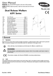
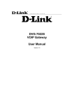
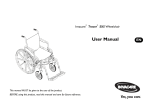
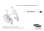
WALKER PLATFORM ATTACHMENT Assembly, Installation and Operating Instructions NOTE: Check ALL parts of the Platform Attachment for shipping damage. If shipping damage is found, DO NOT use. Contact Dealer/Carrier for further instruction. SAFETY SUMMARY (CONTINUED) WARNING The walker platform attachment does not fall under any weight limitation beyond that of the walker that you are attaching it to with a walker maximum weight limitation of 300 pounds. SAFETY SUMMARY The following recommendations are made for the safe installation and use of the Walker Platform Attachment: After platform attachment is installed, refer to your walker instruction sheet for proper use of walker. WARNING DO NOT INSTALL THIS EQUIPMENT UNLESS PRESCRIBED BY A HEALTHCARE PROFESSIONAL (DOCTOR-THERAPIST). Acquaint yourself fully with the use of the platform attachment in the presence of a health care professional (Doctor-Therapist). DO NOT install this equipment without first reading and understanding this instruction sheet. If you are unable to understand the Warnings, Cautions, and Instructions, contact a health care professional, dealer or technical personnel, if applicable, before attempting to install this equipment - otherwise, injury or damage may occur. ATTACHING THE UPPER HARDWARE (FIGURE 1) 1. Remove platform attachment from packaging. WARNING DO NOT USE THE WALKER PLATFORM ATTACHMENT WITH ANY OTHER WALKER ACCESSORIES UNLESS PRESCRIBED BY A HEALTH CARE PROFESSIONAL (DOCTOR-THERAPIST). Ensure that the walker is securely locked into the open position before installing the walker platform attachment. 2. Open walker and secure in locked position before installing the walker platform attachment. Invacare recommends that this walker platform attachment ONLY be attached to an Invacare walker. 3. Determine which side of the walker the platform attachment will be placed. Ensure that ALL attaching hardware is secure. 4. Remove adjustment knob and carriage bolt from U-clamp and half clamp. Ensure that the walker is securely locked into the open position before installing the walker platform attachment - otherwise, injury may occur. 5. Position half clamp over the hand rail with hinge placed toward the inside of the walker on the side of the walker determined in STEP 3. 6. On the outside of the walker side frame, align the mounting hole of the U-clamp with the mounting hole of the half clamp. The walker MUST be level to the ground. ALL four (4) legs of the walker MUST be in contact with the floor when exerting weight onto the walker with the platform attachment. 7. From the inside of the walker, place carriage bolt through the half clamp, U-clamp and into adjustment knob. DO NOT lean too far forward or to the side with the platform attachment as the walker may become unbalanced and injury may occur. 8. Tighten adjustment knob securely. 1 ATTACHING/ADJUSTING THE ARM TUBE (FIGURE 3) Hand Rail U-clamp Attaching Half Clamp 1. Loosen arm tube adjustment knob, located just below the arm pad. 2. Slide arm tube into slot provided located underneath arm pad. Adjustment Knob 3. Adjust arm tube to desired position. Carriage Bolt 4. Securely tighten the arm tube adjustment knob. Adjusting FIGURE 1 -ATTACHING THE UPPER HARDWARE 1. Loosen the arm tube adjustment knob, located just below the arm pad. 2. Slide arm tube in or out to the desired position. 3. Securely tighten the arm tube adjustment knob. ATTACHING THE LOWER HARDWARE (FIGURE 2) NOTE: Position the slides of the lower hardware just below the crossbrace. Arm Tube 1. Loosen adjustment knobs on both slides and place in horizontal position. Loosely tighten adjustment knobs. 2. Continue to adjust slides in or out to provide a tight fit on the frame of the walker. Securely tighten adjustment knobs Arm Pad Arm Tube Adjustment Knob Slot for Arm Tube Crossbrace Slide FIGURE 3 - ATTACHING/ADJUSTING THE ARM TUBE Frame of Walker HEIGHT/ANGLE/TILT ADJUSTMENT Slide Height Adjustment (FIGURE 4) 1. Loosen the adjustment knobs that secure the U-clamps to the half clamps. Adjustment Knob 2. Slide support tube through the U-clamps up or down until desired position is obtained. FIGURE 2 - ATTACHING THE LOWER HARDWARE 3. Securely tighten adjustment knobs that secure the U-clamps to the half clamps. 2 Tilt Adjustment (FIGURE 6) 1. Loosen tilt adjustment knob. NOTE: This is located where the support tube connects with the arm support. Support Tube Adjustment Knobs 2. Lift up or push down on arm tube to obtain the desired tilt. U-clamps 3. Retighten tilt adjustment knob securely. Arm Tube FIGURE 4 - HEIGHT ADJUSTMENT Angle Adjustment (FIGURE 5) Arm Support 1. Loosen the adjustment knobs that secure the support tube to the U-clamps. Angle Adjustment Knob WARNING DO NOT apply full weight while adjusting the angle, injury may result. Support Tube 2. Gently, lay arm on arm pad. 3. Turn the support tube until desired angle is obtained. FIGURE 6 - TILT ADJUSTMENT 4. Retighten adjustment knobs securing the support tube in position. SECURING THE ARM STRAP (FIGURE 7) 1. Unfasten arm strap, by pulling up on fastening strap. 2. Loosen arm strap by pulling through ring. 3. Slide arm into position. 4. Pull fastening strap until a snug fit is obtained. Adjustment Knobs 5. Fold fastening strap over ring and secure to arm strap. U-Clamp Fastening Strap Arm Strap Support Tube Ring U-Clamp FIGURE 5 - ANGLE ADJUSTMENT FIGURE 7 - SECURING THE ARM STRAP 3 NOTE: The sides of the cover are on the outside of the arm support, while the ends are tucked in. Refer to DETAIL "A" for correct orientation. REMOVING THE PLATFORM ATTACHMENT (FIGURE 8) 1. Loosen the adjustment knobs that secure the slides to the walker frame. 2. Adjust slides out away from walker frame. 3. Remove adjustment knob that secures the upper hardware to the walker hand rail. 4. Slide carriage bolt through U-clamp and the half clamp. 5. Remove platform attachment. 6. Lift half clamp off of hand rail. The ends of the cover remain tucked in. 7. For storage purposes, position the Half clamp along side U-clamp, slide carriage bolt through both components and secure with adjustment knob. The sides of the cover slip over outside DETAIL"A" NOTE: This will reduce the risk of losing components and/or hardware. 8. Retighten all adjustment knobs for safe storage. Hand Rail Half Clamp U-clamp Adjustment Knob Slide Adjustment Knob FIGURE 9 - ARM PAD REPLACEMENT Carriage Bolt FASTENING STRAP REPLACEMENT (FIGURE 10) Slide Walker Frame 1. Remove arm pad and cover. Refer to ARM PAD REPLACEMENT in this instruction sheet. NOTE: Note the orientation of the existing arm strap for installation of the new arm strap. FIGURE 8 - REMOVING THE PLATFORM ATTACHMENT 2. Pull on ring and remove fastening strap through arm support. ARM PAD REPLACEMENT (FIGURE 9) 3. Thread the end of the arm strap, without the ring, through slots in the arm support. Make sure the hook end is facing down or the arm strap will not secure properly. NOTE: Note the position of the existing arm pad for correct installation of the new arm pad. 4. Reinstall arm pad and cover Refer to ARM PAD REPLACEMENT in this instruction sheet. 1. Slip existing cover and pad off of arm support. 2. Place new cover and pad on arm support. 4 Ring STORAGE Arm Support The platform attachment does not require removal to fold the walker. Slots 1. Fold the walker per your walker recommendations. 2. Lower the height of the platform attachments if necessary. Refer to the HEIGHT ADJUSTMENT section in this instruction sheet. Hook End CARE AND MAINTENANCE 1. Use a mild soap or detergent to clean the arm pads and dry thoroughly. Pads can be removed refer to ARM PAD REPLACEMENT in this instruction sheet. FIGURE 10 -FASTENING STRAP REPLACEMENT 2. Lubricant can be applied to the threads of the adjustment knobs to aid in preventing rust. 5 2 PARTS LIST 1 3 4 7 5 8 19 2 20 11 10 12 13 6 15 14 11 18 6 16 8 14 17 15 6 ITEM 1 2 3 4 5 6 7 8 10 11 12 13 14 15 16 17 18 19 20 DESCRIPTION ARM STRAP PLUG GRAY PUSH HANDLE GRIP ARM TUBE DVG ARM SUPPORT THREADED INSERT KNOB PAD RD HD CARRIAGE BOLT SPRING PIN CARRIAGE BOLT SLV HALF CLAMP BRACKET SLV UPPER SUPPORT CLAMP SLIDE SUPPORT TUBE UNIVERSAL PLUG GRAY SLV BOTTOM SUPPORT CARRIAGE BOLT LOCKNUT 6 QUANTITY 1 2 1 1 2 6 1 3 1 2 1 1 2 2 1 1 1 2 1 LIMITED WARRANTY PLEASE NOTE: THE WARRANTY BELOW HAS BEEN DRAFTED TO COMPLY WITH FEDERAL LAW APPLICABLE TO PRODUCTS MANUFACTURED AFTER JULY 4, 1975. This warranty is extended only to the original purchaser/user of our product. This warranty gives you specific legal rights and you may also have other legal rights which vary from state to state. Invacare warrants the platform attachment to be free from defects in materials and workmanship for the lifetime of the original purchaser/user. If within such warranty period any such product shall be proven to be defective, such product shall be repaired or replaced, at Invacares option. This warranty does not include any labor or shipping charges incurred in replacement part installation or repair of any such product. Invacares sole obligation and your exclusive remedy under this warranty shall be limited to such repair and/or replacement. If within such warranty period any such product shall be proven to be defective, such product shall be repaired or replaced, at Invacares option. This warranty does not include any labor or shipping charges incurred in replacement part installation or repair of any such product. Invacares sole obligation and your exclusive remedy under this warranty shall be limited to such repair and/or replacement. For warranty service, please contact the dealer from whom you purchased your Invacare product. In the event you do not receive satisfactory warranty service, please write directly to Invacare at the address below, provide dealers name, address, and the date of purchase, indicate nature of the defect and, if the product is serialized, indicate the serial number. Do not return products to our factory without our prior consent. Limitations and Exclusions: The foregoing warranty shall not apply to serial numbered products if the serial number has been removed or defaced; products subjected to negligence, accident, improper operation, improper maintenance or storage, commercial or institutional use; products modified without Invacares express written consent including, but not limited to, modification through the use of unauthorized parts or attachments; products damaged by reason of repairs made to any component without the specific consent of Invacare; or to a product damaged by circumstances beyond Invacares control. Such evaluation will be solely determined by Invacare. The warranty shall not apply to problems arising from normal wear or failure to adhere to the following instructions. THE FOREGOING WARRANTY IS EXCLUSIVE AND IN LIEU OF ALL OTHER EXPRESS WARRANTIES. IMPLIED WARRANTIES, IF ANY, INCLUDING THE IMPLIED WARRANTIES OF MERCHANTABILITY AND FITNESS FOR A PARTICULAR PURPOSE, SHALL NOT EXTEND BEYOND THE DURATION OF THE EXPRESS WARRANTY PROVIDED HEREIN AND THE REMEDY FOR VIOLATIONS OF ANY IMPLIED WARRANTY SHALL BE LIMITED TO REPAIR OR REPLACEMENT OF THE DEFECTIVE PRODUCT PURSUANT TO THE TERMS CONTAINED HEREIN. INVACARE SHALL NOT BE LIABLE FOR ANY CONSEQUENTIAL OR INCIDENTAL DAMAGES WHATSOEVER. SOME STATES DO NOT ALLOW THE EXCLUSION OR LIMITATION OF INCIDENTAL OR CONSEQUENTIAL DAMAGE, OR LIMITATION ON HOW LONG AN IMPLIED WARRANTY LASTS, SO THE ABOVE EXCLUSIONS AND LIMITATIONS MAY NOT APPLY TO YOU. THIS WARRANTY SHALL BE EXTENDED TO COMPLY WITH STATE/PROVINCIAL LAWS AND REQUIREMENTS. 7 INVACARE CORPORATION l 899 Cleveland Street l P.O. Box 4028 l Elyria, Ohio 44036-2125 l Phone 1-(800)-333-6900 Form No. 97-169 (1064716) Rev. 8/97 Printed in U.S.A.