1
JY997D14001K
Side
B
B
Applicable standards
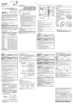
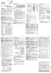
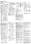
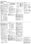
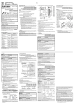
1.2 External Dimensions, Part Names, and Terminal Layout
FX3U-4DA-ADP units made in June, 2005 or later comply with the EC Directive (EMC
FX3U-4DA-ADP
USER'S MANUAL
Manual Number
JY997D14001
Revision
K
Date
April 2015
This manual describes the part names, dimensions, mounting, and specifications
of the product. Before use, read this manual and the manuals of all relevant
products fully to acquire proficiency in handling and operating the product. Make
sure to learn all the product information, safety information, and precautions.
Store this manual in a safe place so that it can be taken out and read whenever
necessary. Always forward it to the end user.
Registration:
The company and product names described in this manual are registered
trademarks or the trademarks of their respective companies.
Effective April 2015
Specifications are subject to change without notice.
© 2005 Mitsubishi Electric Corporation
and
.
Indicates that incorrect handling may cause hazardous
conditions, resulting in death or severe injury.
Indicates that incorrect handling may cause hazardous
conditions, resulting in medium or slight personal injury
or physical damage.
Depending on the circumstances, procedures indicated by
also cause severe injury.
It is important to follow all precautions for personal safety.
may
Manual No.
Description
FX 3S/FX 3G/FX 3GC/FX 3U/
FX3UC Series
User's Manual
- Analog Control Edition
JY997D16701
MODEL CODE:
09R619
Describes specifications for
analog control and
programming method for
FX3S/FX3G/FX3GC/FX3U/
FX3UC Series PLC.
FX 3S/FX 3G/FX 3GC/FX 3U/
FX3UC Series
Programming Manual
- Basic & Applied
Instruction Edition
JY997D16601
MODEL CODE:
09R517
Describes PLC programming
for basic/applied instructions
and devices.
FX3S Series
User’s Manual
- Hardware Edition
JY997D48601
MODEL CODE:
09R535
Explains FX 3S Series PLC
specifications for I/O, wiring,
installation, and maintenance.
FX3G Series
User’s Manual
- Hardware Edition
JY997D31301
MODEL CODE:
09R521
Explains FX 3G Series PLC
specifications for I/O, wiring,
installation, and maintenance.
FX3GC Series
User’s Manual
- Hardware Edition
JY997D45401
MODEL CODE:
09R533
Explains FX 3GC Series PLC
specifications for I/O, wiring,
installation, and maintenance.
FX3U Series
User’s Manual
- Hardware Edition
JY997D16501
MODEL CODE:
09R516
Explains FX 3U Series PLC
specifications for I/O, wiring,
installation, and maintenance.
FX3UC Series
User’s Manual
- Hardware Edition
JY997D28701
MODEL CODE:
09R519
Explains FX 3UC Series PLC
specifications for I/O, wiring,
installation, and maintenance.
[6]
[2]
[7]
V1+
[8]
[1]
I1+
COM1
V2+
I2+
COM2
V3+
I3+
Note
• Authorized Representative in the European Community:
Mitsubishi Electric Europe B.V.
Gothaer Str. 8, 40880 Ratingen, Germany
COM3
V4+
7(0.28")
Caution for EC Directive
The analog special adapters have been found to be compliant to the European
standards in the aforesaid manual and directive. However, for the very best performance from what are in fact delicate measuring and controlled output device
Mitsubishi Electric would like to make the following points;
As analog devices are sensitive by nature, their use should be considered carefully. For users of proprietary cables (integral with sensors or actuators), these
users should follow those manufacturers installation requirements.
Mitsubishi Electric recommend that shielded cables should be used. If NO other
EMC protection is provided, then users may experience temporary loss or
accuracy between ±10 % in very heavy industrial areas.
However, Mitsubishi Electric suggest that if adequate EMC precautions are followed for the users complete control system, users should expect accuracy as
specified in this manual.
• Sensitive analog cable should not be laid in the same trunking or cable
conduit as high voltage cabling. Where possible users should run analog
cables separately.
• Good cable shielding should be used. When terminating the shield at Earth
- ensure that no earth loops are accidentally created.
• When reading analog values, EMC accuracy can be improved out by
averaging the readings. This can be achieved either through functions on the
analog special adapters or through a users program.
1. Outline
The FX3U-4DA-ADP special adapter for analog output (hereinafter called 4DA-ADP) is
a special adapter to add four analog output points.
Verify that the following product and items are included in the package:
Manual name
24-
Attention
• This product is designed for use in industrial applications.
1.1 Incorporated Items
Associated Manuals
[4]
Product
FX3U-4DA-ADP analog output special adapter
Accessories
User’s manual (This manual)
74(2.92")
I4+
15.1
(0.6")
17.6
(0.7")
15.5
(0.62")
[11]
Special adapter
connector cover
is removed
[9]
This section describes the connection method to the PLC (FX3U Series PLC is
used for the following example).
For installation method to other PLCs, refer to the respective PLC User's manual
Hardware Edition.
Procedure
1) Turn off the power.
Disconnect all the cables connected to the PLC main unit and special adapter,
and demount the main unit and special adapter mounted on DIN rail or
mounted directly using screws.
2) Install an expansion board to the main unit.
For the expansion board installation procedure, refer to the following manual:
→ FX3U Series User's Manual - Hardware Edition
3) Remove the special adapter connector cover
on the expansion board (fig.A).
When connecting this product to another
4)
special adapter, please replace the
'expansion board' in the above description
with a 'special adapter' and perform the
procedure as indicated.
3)
B
4) Slide the special adapter slide lock
3U
FX
-48M
3U
N
RU
OP
COM4
Weight: Approx. 0.1 kg (0.22 lbs)
[1] DIN rail mounting groove (DIN rail: DIN46277)
[2] Name plate
[3] Special adapter slide lock:
Used to connect additional special adapters onto the left side of this special
adapter.
[4] Special adapter connector cover:
Remove this cover to connect additional special adapters to the left side.
[5] Direct mounting hole:2 holes of φ4.5 (0.18") (mounting screw: M4 screw)
Not used when connecting to FX3GC/FX3UC Series PLC.
[6] POWER LED (green):
Lit while 24 V DC power is supplied properly to terminals '24+' and '24-'.
[7] Terminal block (European type):
Connect the analog output voltage/current signal, and 24 V DC power supply.
[8] Special adapter connector:
Used to connect this special adapter to PLC main unit or special adapter.
[9] DIN rail mounting hook
[10] Special adapter fixing hook
[11] Special adapter connector:
Used to connect communication or analog special adapters to the left side of the
4DA-ADP.
ST
(fig.B) of the main unit.
When connecting this product to another
special adapter, please replace the 'main
unit' in the above description with a 'special
adapter' and perform the procedure as
indicated. (Please replace the following
procedures similarly.)
5) Connect the
special adapter
C
(fig.C) to the
main unit as
shown on the
right.
6) Slide back the
special adapter
slide lock (fig.B)
of the main unit
to fix the special
adapter (fig.C).
FX
4)
A
B
B
FX3U-48M
S
R/E
8M
3U
***
***
-48M FX3U-4
3U
FX
R
E
W
O
This manual classifies the safety precautions into two categories:
[3]
2.1 Connection to the PLC
24+
P
Safety Precaution (Read these precautions before use.)
Directive) and UL standards (UL, cUL). Further information can be found in the
following manual.
→ FX3S Series Hardware Manual (Manual No. JY997D48301)
→ FX3G Series Hardware Manual (Manual No. JY997D46001)
→ FX3GC Series Hardware Manual (Manual No. JY997D45201)
→ FX3U Series Hardware Manual (Manual No. JY997D18801)
→ FX3UC (D, DS, DSS) Series Hardware Manual (Manual No. JY997D28601)
→ FX3UC-32MT-LT-2 Hardware Manual (Manual No. JY997D31601)
Regarding the standards that relate to the main unit, please refer to either the FX
series product catalog or consult with your nearest Mitsubishi product provider.
[10]
[5]
-4
8M
R
/E
S
ENGLISH
A
FX
JAPANESE
Side
90(3.55")
98(3.86")
(mounting hole pitch)
106(4.18")
Side
6)
N
RU
OP
ST
5)
6)
5)
5)
B
Connection precautions
Connect all the high-speed I/O special adapters before connecting other
special adapters when they are used in combination.
Do not connect a high-speed I/O special adapter on the left side of any
special adapters other than other high-speed I/O special adapters.
2. Installation
For installation/uninstallation details, refer to the respective PLC User's manual
Hardware Edition.
INSTALLATION
PRECAUTIONS
• Make sure to cut off all phases of the power supply externally before attempting
installation or wiring work.
Failure to do so may cause electric shock or damage to the product.
INSTALLATION
PRECAUTIONS
• Use the product within the generic environment specifications described in PLC
main unit manual (Hardware Edition).
Never use the product in areas with excessive dust, oily smoke, conductive dusts,
corrosive gas (salt air, Cl 2 , H 2 S, SO 2 , or NO 2 ), flammable gas, vibration or
impacts, or expose it to high temperature, condensation, or rain and wind.
If the product is used in such conditions, electric shock, fire, malfunctions,
deterioration or damage may occur.
• When drilling screw holes or wiring, make sure cutting or wire debris does not
enter the ventilation slits.
Failure to do so may cause fire, equipment failures or malfunctions.
• Do not touch the conductive parts of the product directly.
Doing so may cause device failures or malfunctions.
• Connect special adapter securely to their designated connectors.
Loose connections may cause malfunctions.
How to obtain manuals
For product manuals or documents, consult with the Mitsubishi Electric dealer
from who you purchased your product.
3. Wiring
3.2 Power Supply Wiring
WIRING
PRECAUTIONS
• When drilling screw holes or wiring, make sure cutting or wire debris does
not enter the ventilation slits.
Failure to do so may cause fire, equipment failures or malfunctions.
• Make sure to observe the following precautions in order to prevent any
damage to the machinery or accidents due to abnormal data written to the
PLC under the influence of noise:
1) Do not bundle the power line or shield of the analog input/output cable
together with or lay it close to the main circuit, high-voltage line, or load
line.
Otherwise, noise disturbance and/or surge induction are likely to take
place. As a guideline, lay the control line at least 100mm (3.94") or more
away from the main circuit, high-voltage line, or load line.
2) Ground the shield of the analog input/output cable at one point on the
signal receiving side. However, do not use common grounding with heavy
electrical systems.
• Make sure to properly wire to the terminal block (European type) in
accordance with the following precautions.
Failure to do so may cause electric shock, equipment failures, a short-circuit,
wire breakage, malfunctions, or damage to the product.
- The disposal size of the cable end should follow the dimensions
described in the manual.
- Tightening torque should follow the specifications in the manual.
- Twist the end of strand wire and make sure that there are no loose wires.
- Do not solder-plate the electric wire ends.
- Do not connect more than the specified number of wires or electric wires
of unspecified size.
- Affix the electric wires so that neither the terminal block nor the connected
parts are directly stressed.
• Make sure to properly wire the terminal block in accordance with the
following precautions.
Failure to do so may cause electric shock, equipment failures, a short-circuit,
wire breakage, malfunctions, or damage to the product.
- The disposal size of the cable end should follow the dimensions
described in the manual of the PLC main unit.
- Tightening torque should follow the specifications in the manual of the
PLC main unit.
3.1 Applicable cable and terminal tightening torque
Terminal block (European type)
Type
2-wire
2 pieces of 0.3 mm2 (AWG22)
3) Termination of cable end
Strip the coating of strand wire and twist the cable core before connecting it,
or strip the coating of single wire before connecting it.
An alternative connection is to use a ferrule with insulating sleeve.
<Reference>
Manufacturer
Model
Caulking tool
Phoenix Contact Co., Ltd.
AI 0.5-8WH
CRIMPFOX 6*1
(or CRIMPFOX 6T-F*2)
Ver. 1.00 or later (from first production)
FX3GC Series PLC
Ver. 1.40 or later (from first production)
FX3U Series PLC
Ver. 2.20 or later (from first production)
FX3UC Series PLC
Ver. 1.20 or later (from the production manufactured in May,
2004 with SER No. 45****)
The version number can be checked by monitoring D8001/D8101 as the last three
digits indicate it.
V +
I +
ch
COM
*3
+15 V
External power
supply wiring
represents the channel number.
*2 24 V DC service power supply of the FX3S/FX3G/FX3U Series PLC can also be
used.
*3 Ground the shielded wire at one point on the signal receiving side.
3.4 Grounding
Grounding should be performed as stated below.
• The grounding resistance should be 100 Ω or less.
• Independent grounding should be performed for best results.
When independent grounding is not performed, perform "shared grounding" of the
following figure.
For details, refer to the respective PLC User's manual Hardware Edition.
PLC
Other
equipment
PLC
Other
equipment
4.3 Power Supply Specifications
Item
Specification
D/A conversion
24 V DC +20 %/-15 %, 150 mA for 24 V DC
circuit driving power Connect a 24 V DC power supply to the terminal block.
5 V DC, 15 mA
5 V DC power is supplied from the internal power supply of
main unit.
Interface driving
power
4.4 Performance Specifications
Description
Item
Analog output
range
Voltage output
Current output
0 to 10 V DC
(External load: 5 kΩ to 1 MΩ)
4 to 20 mA DC
(External load: 500 Ω or less)
Digital input
Independent grounding
Best condition
Shared grounding
Good condition
Common grounding
Not allowed
Total accuracy
• Do not disassemble or modify the PLC.
Doing so may cause fire, equipment failures, or malfunctions.
* For repair, contact your local Mitsubishi Electric representative.
• Do not drop the product or exert strong impact to it.
Doing so may cause damage.
4 μA(16 mA/4000)
2.5 mV(10 V/4000)
• ±0.5 % (±50 mV) for full
scale of 10 V (when
ambient temperature is
25 °C±5 °C)
• ±1.0 % (±100 mV) for full
scale of 10 V (when
ambient temperature is
0 °C to 55 °C)
• The grounding wire size should be AWG 22-20 (0.3-0.5 mm2).
• The grounding point should be close to the PLC, and all grounding wire should be
as short as possible.
If the external load resistance
(Rs) is less than 5 kΩ, the
value calculated from the
following formula will be
added: (Addition will be
100 mV per %.)
• ±0.5 % (±80 μA) for full scale
of 16 mA (when ambient
temperature is 25 °C±5 °C)
• ±1.0 % (±160 μA) for full scale
of 16 mA (when ambient
temperature is 0 °C to 55 °C)
47×100
0.9 %
Rs+47
for full scale of 10 V
DISPOSAL
PRECAUTIONS
• Please contact a certified electronic waste disposal company for the
environmentally safe recycling and disposal of your device.
12 bits, binary
Resolution
D/A conversion
time
• FX3U/FX3UC Series PLC: 200 μs
(The data will be updated at every scan time of the PLC.)
• FX3S/FX3G/FX3GC Series PLC: 250 μs
(The data will be updated at every scan time of the PLC.)
9mm
(0.35")
• The product is a precision instrument. During transportation, avoid any impacts.
Failure to do so may cause failures in the product. After transportation, verify the
operations of the product.
Output
characteristics
8mm
(0.31")
14mm(0.55")
When using a stick terminal with insulating sleeve, choose a wire with proper
cable sheath referring to the above outside dimensions, or otherwise, the wire
cannot be inserted easily.
The tightening torque must be 0.22 to 0.25 N•m. Do not tighten terminal
screws exceeding the specified torque. Failure to do so may cause equipment
failures or malfunctions.
10V
20mA
Analog output
- Stick terminal with insulating sleeve
Insulation sleeve
Contact area
(Crimp area)
Analog output
*2 Old model name: CRIMPFOX UD 6
2.6mm(0.1")
Specification
500 V AC for one minute
Between all terminals and
ground terminal of PLC
5 M Ω o r m o r e b y 5 0 0 V D C main unit
Insulation resistance
megger
*1 Use 2-core shielded twisted pair cable for the analog output lines, and separate
the analog output lines from other power lines or inductive lines.
Other
equipment
Items other than the following are equivalent to the those of the PLC main unit.
For general specifications, refer to the respective PLC User's manual Hardware
Edition.
Dielectric withstand
voltage
Grounding
(Ground resistance:
100 Ω or less)
:
4.2 General Specifications
Item
24+
24-
24 V DC
*2
PLC
FX3G Series PLC
COM
*3
Using current
output
V +, I +, ch
Applicability
Ver. 1.00 or later (from first production)
TRANSPORTATION AND
STORAGE PRECAUTIONS
*1 Old model name: CRIMPFOX ZA 3
- Strand wire/single wire
ch
STARTUP AND
MAINTENANCE
PRECAUTIONS
Wire size
0.3 mm2 to 0.5 mm2 (AWG22 to 20)
Terminal
block
V +
I +
4DA-ADP
4. Specifications
1) Wire size
Wiring to analog device should use 20-22 AWG wire.
2) Applicable cable
Single-wire
→ For the terminal configuration, refer to Section 1.2
Using voltage
output
*1 Shielded
Model name
FX3S Series PLC
3.3 Wiring of Analog Output
• Make sure to cut off all phases of the power supply externally before
attempting installation or wiring work.
Failure to do so may cause electric shock or damage to the product.
3.1.1
4.1 Applicable PLC
For the power supply wiring, refer to the following manual.
→ FX3S/FX3G/FX3GC/FX3U/FX3UC Series User’s Manual - Analog Control Edition
WIRING
PRECAUTIONS
4000 4080
Digital input
Warranty
Mitsubishi will not be held liable for damage caused by factors found not to be
the cause of Mitsubishi; opportunity loss or lost profits caused by faults in the
Mitsubishi products; damage, secondary damage, accident compensation
caused by special factors unpredictable by Mitsubishi; damages to products
other than Mitsubishi products; and to other duties.
For safe use
4mA
0
This manual confers no industrial property rights or any rights of any other kind,
nor does it confer any patent licenses. Mitsubishi Electric Corporation cannot be
held responsible for any problems involving industrial property rights which may
occur as a result of using the contents noted in this manual.
0
4000 4080
Digital input
Insulation
method
• The photocoupler is adopted to insulate the analog output area
from the PLC.
• The DC/DC converter is adopted to insulate the power supply
line from the analog output area.
• Channels are not insulated from each other.
Occupied
points
0 point (This number is not related to the maximum number of
input/output points of the PLC.)
• This product has been manufactured as a general-purpose part for general
industries, and has not been designed or manufactured to be incorporated in
a device or system used in purposes related to human life.
• Before using the product for special purposes such as nuclear power, electric
power, aerospace, medicine or passenger movement vehicles, consult with
Mitsubishi Electric.
• This product has been manufactured under strict quality control. However
when installing the product where major accidents or losses could occur if the
product fails, install appropriate backup or failsafe functions in the system.
HEAD OFFICE : TOKYO BUILDING, 2-7-3 MARUNOUCHI, CHIYODA-KU, TOKYO 100-8310, JAPAN
JY997D14001K
Side
B
B
Applicable standards
1.2 External Dimensions, Part Names, and Terminal Layout
FX3U-4DA-ADP units made in June, 2005 or later comply with the EC Directive (EMC
FX3U-4DA-ADP
USER'S MANUAL
Manual Number
JY997D14001
Revision
K
Date
April 2015
This manual describes the part names, dimensions, mounting, and specifications
of the product. Before use, read this manual and the manuals of all relevant
products fully to acquire proficiency in handling and operating the product. Make
sure to learn all the product information, safety information, and precautions.
Store this manual in a safe place so that it can be taken out and read whenever
necessary. Always forward it to the end user.
Registration:
The company and product names described in this manual are registered
trademarks or the trademarks of their respective companies.
Effective April 2015
Specifications are subject to change without notice.
© 2005 Mitsubishi Electric Corporation
and
.
Indicates that incorrect handling may cause hazardous
conditions, resulting in death or severe injury.
Indicates that incorrect handling may cause hazardous
conditions, resulting in medium or slight personal injury
or physical damage.
Depending on the circumstances, procedures indicated by
also cause severe injury.
It is important to follow all precautions for personal safety.
may
Manual No.
Description
FX 3S/FX 3G/FX 3GC/FX 3U/
FX3UC Series
User's Manual
- Analog Control Edition
JY997D16701
MODEL CODE:
09R619
Describes specifications for
analog control and
programming method for
FX3S/FX3G/FX3GC/FX3U/
FX3UC Series PLC.
FX 3S/FX 3G/FX 3GC/FX 3U/
FX3UC Series
Programming Manual
- Basic & Applied
Instruction Edition
JY997D16601
MODEL CODE:
09R517
Describes PLC programming
for basic/applied instructions
and devices.
FX3S Series
User’s Manual
- Hardware Edition
JY997D48601
MODEL CODE:
09R535
Explains FX 3S Series PLC
specifications for I/O, wiring,
installation, and maintenance.
FX3G Series
User’s Manual
- Hardware Edition
JY997D31301
MODEL CODE:
09R521
Explains FX 3G Series PLC
specifications for I/O, wiring,
installation, and maintenance.
FX3GC Series
User’s Manual
- Hardware Edition
JY997D45401
MODEL CODE:
09R533
Explains FX 3GC Series PLC
specifications for I/O, wiring,
installation, and maintenance.
FX3U Series
User’s Manual
- Hardware Edition
JY997D16501
MODEL CODE:
09R516
Explains FX 3U Series PLC
specifications for I/O, wiring,
installation, and maintenance.
FX3UC Series
User’s Manual
- Hardware Edition
JY997D28701
MODEL CODE:
09R519
Explains FX 3UC Series PLC
specifications for I/O, wiring,
installation, and maintenance.
[6]
[2]
[7]
V1+
[8]
[1]
I1+
COM1
V2+
I2+
COM2
V3+
I3+
Note
• Authorized Representative in the European Community:
Mitsubishi Electric Europe B.V.
Gothaer Str. 8, 40880 Ratingen, Germany
COM3
V4+
7(0.28")
Caution for EC Directive
The analog special adapters have been found to be compliant to the European
standards in the aforesaid manual and directive. However, for the very best performance from what are in fact delicate measuring and controlled output device
Mitsubishi Electric would like to make the following points;
As analog devices are sensitive by nature, their use should be considered carefully. For users of proprietary cables (integral with sensors or actuators), these
users should follow those manufacturers installation requirements.
Mitsubishi Electric recommend that shielded cables should be used. If NO other
EMC protection is provided, then users may experience temporary loss or
accuracy between ±10 % in very heavy industrial areas.
However, Mitsubishi Electric suggest that if adequate EMC precautions are followed for the users complete control system, users should expect accuracy as
specified in this manual.
• Sensitive analog cable should not be laid in the same trunking or cable
conduit as high voltage cabling. Where possible users should run analog
cables separately.
• Good cable shielding should be used. When terminating the shield at Earth
- ensure that no earth loops are accidentally created.
• When reading analog values, EMC accuracy can be improved out by
averaging the readings. This can be achieved either through functions on the
analog special adapters or through a users program.
1. Outline
The FX3U-4DA-ADP special adapter for analog output (hereinafter called 4DA-ADP) is
a special adapter to add four analog output points.
Verify that the following product and items are included in the package:
Manual name
24-
Attention
• This product is designed for use in industrial applications.
1.1 Incorporated Items
Associated Manuals
[4]
Product
FX3U-4DA-ADP analog output special adapter
Accessories
User’s manual (This manual)
74(2.92")
I4+
15.1
(0.6")
17.6
(0.7")
15.5
(0.62")
[11]
Special adapter
connector cover
is removed
[9]
This section describes the connection method to the PLC (FX3U Series PLC is
used for the following example).
For installation method to other PLCs, refer to the respective PLC User's manual
Hardware Edition.
Procedure
1) Turn off the power.
Disconnect all the cables connected to the PLC main unit and special adapter,
and demount the main unit and special adapter mounted on DIN rail or
mounted directly using screws.
2) Install an expansion board to the main unit.
For the expansion board installation procedure, refer to the following manual:
→ FX3U Series User's Manual - Hardware Edition
3) Remove the special adapter connector cover
on the expansion board (fig.A).
When connecting this product to another
4)
special adapter, please replace the
'expansion board' in the above description
with a 'special adapter' and perform the
procedure as indicated.
3)
B
4) Slide the special adapter slide lock
3U
FX
-48M
3U
N
RU
OP
COM4
Weight: Approx. 0.1 kg (0.22 lbs)
[1] DIN rail mounting groove (DIN rail: DIN46277)
[2] Name plate
[3] Special adapter slide lock:
Used to connect additional special adapters onto the left side of this special
adapter.
[4] Special adapter connector cover:
Remove this cover to connect additional special adapters to the left side.
[5] Direct mounting hole:2 holes of φ4.5 (0.18") (mounting screw: M4 screw)
Not used when connecting to FX3GC/FX3UC Series PLC.
[6] POWER LED (green):
Lit while 24 V DC power is supplied properly to terminals '24+' and '24-'.
[7] Terminal block (European type):
Connect the analog output voltage/current signal, and 24 V DC power supply.
[8] Special adapter connector:
Used to connect this special adapter to PLC main unit or special adapter.
[9] DIN rail mounting hook
[10] Special adapter fixing hook
[11] Special adapter connector:
Used to connect communication or analog special adapters to the left side of the
4DA-ADP.
ST
(fig.B) of the main unit.
When connecting this product to another
special adapter, please replace the 'main
unit' in the above description with a 'special
adapter' and perform the procedure as
indicated. (Please replace the following
procedures similarly.)
5) Connect the
special adapter
C
(fig.C) to the
main unit as
shown on the
right.
6) Slide back the
special adapter
slide lock (fig.B)
of the main unit
to fix the special
adapter (fig.C).
FX
4)
A
B
B
FX3U-48M
S
R/E
8M
3U
***
***
-48M FX3U-4
3U
FX
R
E
W
O
This manual classifies the safety precautions into two categories:
[3]
2.1 Connection to the PLC
24+
P
Safety Precaution (Read these precautions before use.)
Directive) and UL standards (UL, cUL). Further information can be found in the
following manual.
→ FX3S Series Hardware Manual (Manual No. JY997D48301)
→ FX3G Series Hardware Manual (Manual No. JY997D46001)
→ FX3GC Series Hardware Manual (Manual No. JY997D45201)
→ FX3U Series Hardware Manual (Manual No. JY997D18801)
→ FX3UC (D, DS, DSS) Series Hardware Manual (Manual No. JY997D28601)
→ FX3UC-32MT-LT-2 Hardware Manual (Manual No. JY997D31601)
Regarding the standards that relate to the main unit, please refer to either the FX
series product catalog or consult with your nearest Mitsubishi product provider.
[10]
[5]
-4
8M
R
/E
S
ENGLISH
A
FX
JAPANESE
Side
90(3.55")
98(3.86")
(mounting hole pitch)
106(4.18")
Side
6)
N
RU
OP
ST
5)
6)
5)
5)
B
Connection precautions
Connect all the high-speed I/O special adapters before connecting other
special adapters when they are used in combination.
Do not connect a high-speed I/O special adapter on the left side of any
special adapters other than other high-speed I/O special adapters.
2. Installation
For installation/uninstallation details, refer to the respective PLC User's manual
Hardware Edition.
INSTALLATION
PRECAUTIONS
• Make sure to cut off all phases of the power supply externally before attempting
installation or wiring work.
Failure to do so may cause electric shock or damage to the product.
INSTALLATION
PRECAUTIONS
• Use the product within the generic environment specifications described in PLC
main unit manual (Hardware Edition).
Never use the product in areas with excessive dust, oily smoke, conductive dusts,
corrosive gas (salt air, Cl 2 , H 2 S, SO 2 , or NO 2 ), flammable gas, vibration or
impacts, or expose it to high temperature, condensation, or rain and wind.
If the product is used in such conditions, electric shock, fire, malfunctions,
deterioration or damage may occur.
• When drilling screw holes or wiring, make sure cutting or wire debris does not
enter the ventilation slits.
Failure to do so may cause fire, equipment failures or malfunctions.
• Do not touch the conductive parts of the product directly.
Doing so may cause device failures or malfunctions.
• Connect special adapter securely to their designated connectors.
Loose connections may cause malfunctions.
How to obtain manuals
For product manuals or documents, consult with the Mitsubishi Electric dealer
from who you purchased your product.
3. Wiring
3.2 Power Supply Wiring
WIRING
PRECAUTIONS
• When drilling screw holes or wiring, make sure cutting or wire debris does
not enter the ventilation slits.
Failure to do so may cause fire, equipment failures or malfunctions.
• Make sure to observe the following precautions in order to prevent any
damage to the machinery or accidents due to abnormal data written to the
PLC under the influence of noise:
1) Do not bundle the power line or shield of the analog input/output cable
together with or lay it close to the main circuit, high-voltage line, or load
line.
Otherwise, noise disturbance and/or surge induction are likely to take
place. As a guideline, lay the control line at least 100mm (3.94") or more
away from the main circuit, high-voltage line, or load line.
2) Ground the shield of the analog input/output cable at one point on the
signal receiving side. However, do not use common grounding with heavy
electrical systems.
• Make sure to properly wire to the terminal block (European type) in
accordance with the following precautions.
Failure to do so may cause electric shock, equipment failures, a short-circuit,
wire breakage, malfunctions, or damage to the product.
- The disposal size of the cable end should follow the dimensions
described in the manual.
- Tightening torque should follow the specifications in the manual.
- Twist the end of strand wire and make sure that there are no loose wires.
- Do not solder-plate the electric wire ends.
- Do not connect more than the specified number of wires or electric wires
of unspecified size.
- Affix the electric wires so that neither the terminal block nor the connected
parts are directly stressed.
• Make sure to properly wire the terminal block in accordance with the
following precautions.
Failure to do so may cause electric shock, equipment failures, a short-circuit,
wire breakage, malfunctions, or damage to the product.
- The disposal size of the cable end should follow the dimensions
described in the manual of the PLC main unit.
- Tightening torque should follow the specifications in the manual of the
PLC main unit.
3.1 Applicable cable and terminal tightening torque
Terminal block (European type)
Type
2-wire
2 pieces of 0.3 mm2 (AWG22)
3) Termination of cable end
Strip the coating of strand wire and twist the cable core before connecting it,
or strip the coating of single wire before connecting it.
An alternative connection is to use a ferrule with insulating sleeve.
<Reference>
Manufacturer
Model
Caulking tool
Phoenix Contact Co., Ltd.
AI 0.5-8WH
CRIMPFOX 6*1
(or CRIMPFOX 6T-F*2)
Ver. 1.00 or later (from first production)
FX3GC Series PLC
Ver. 1.40 or later (from first production)
FX3U Series PLC
Ver. 2.20 or later (from first production)
FX3UC Series PLC
Ver. 1.20 or later (from the production manufactured in May,
2004 with SER No. 45****)
The version number can be checked by monitoring D8001/D8101 as the last three
digits indicate it.
V +
I +
ch
COM
*3
+15 V
External power
supply wiring
represents the channel number.
*2 24 V DC service power supply of the FX3S/FX3G/FX3U Series PLC can also be
used.
*3 Ground the shielded wire at one point on the signal receiving side.
3.4 Grounding
Grounding should be performed as stated below.
• The grounding resistance should be 100 Ω or less.
• Independent grounding should be performed for best results.
When independent grounding is not performed, perform "shared grounding" of the
following figure.
For details, refer to the respective PLC User's manual Hardware Edition.
PLC
Other
equipment
PLC
Other
equipment
4.3 Power Supply Specifications
Item
Specification
D/A conversion
24 V DC +20 %/-15 %, 150 mA for 24 V DC
circuit driving power Connect a 24 V DC power supply to the terminal block.
5 V DC, 15 mA
5 V DC power is supplied from the internal power supply of
main unit.
Interface driving
power
4.4 Performance Specifications
Description
Item
Analog output
range
Voltage output
Current output
0 to 10 V DC
(External load: 5 kΩ to 1 MΩ)
4 to 20 mA DC
(External load: 500 Ω or less)
Digital input
Independent grounding
Best condition
Shared grounding
Good condition
Common grounding
Not allowed
Total accuracy
• Do not disassemble or modify the PLC.
Doing so may cause fire, equipment failures, or malfunctions.
* For repair, contact your local Mitsubishi Electric representative.
• Do not drop the product or exert strong impact to it.
Doing so may cause damage.
4 μA(16 mA/4000)
2.5 mV(10 V/4000)
• ±0.5 % (±50 mV) for full
scale of 10 V (when
ambient temperature is
25 °C±5 °C)
• ±1.0 % (±100 mV) for full
scale of 10 V (when
ambient temperature is
0 °C to 55 °C)
• The grounding wire size should be AWG 22-20 (0.3-0.5 mm2).
• The grounding point should be close to the PLC, and all grounding wire should be
as short as possible.
If the external load resistance
(Rs) is less than 5 kΩ, the
value calculated from the
following formula will be
added: (Addition will be
100 mV per %.)
• ±0.5 % (±80 μA) for full scale
of 16 mA (when ambient
temperature is 25 °C±5 °C)
• ±1.0 % (±160 μA) for full scale
of 16 mA (when ambient
temperature is 0 °C to 55 °C)
47×100
0.9 %
Rs+47
for full scale of 10 V
DISPOSAL
PRECAUTIONS
• Please contact a certified electronic waste disposal company for the
environmentally safe recycling and disposal of your device.
12 bits, binary
Resolution
D/A conversion
time
• FX3U/FX3UC Series PLC: 200 μs
(The data will be updated at every scan time of the PLC.)
• FX3S/FX3G/FX3GC Series PLC: 250 μs
(The data will be updated at every scan time of the PLC.)
9mm
(0.35")
• The product is a precision instrument. During transportation, avoid any impacts.
Failure to do so may cause failures in the product. After transportation, verify the
operations of the product.
Output
characteristics
8mm
(0.31")
14mm(0.55")
When using a stick terminal with insulating sleeve, choose a wire with proper
cable sheath referring to the above outside dimensions, or otherwise, the wire
cannot be inserted easily.
The tightening torque must be 0.22 to 0.25 N•m. Do not tighten terminal
screws exceeding the specified torque. Failure to do so may cause equipment
failures or malfunctions.
10V
20mA
Analog output
- Stick terminal with insulating sleeve
Insulation sleeve
Contact area
(Crimp area)
Analog output
*2 Old model name: CRIMPFOX UD 6
2.6mm(0.1")
Specification
500 V AC for one minute
Between all terminals and
ground terminal of PLC
5 M Ω o r m o r e b y 5 0 0 V D C main unit
Insulation resistance
megger
*1 Use 2-core shielded twisted pair cable for the analog output lines, and separate
the analog output lines from other power lines or inductive lines.
Other
equipment
Items other than the following are equivalent to the those of the PLC main unit.
For general specifications, refer to the respective PLC User's manual Hardware
Edition.
Dielectric withstand
voltage
Grounding
(Ground resistance:
100 Ω or less)
:
4.2 General Specifications
Item
24+
24-
24 V DC
*2
PLC
FX3G Series PLC
COM
*3
Using current
output
V +, I +, ch
Applicability
Ver. 1.00 or later (from first production)
TRANSPORTATION AND
STORAGE PRECAUTIONS
*1 Old model name: CRIMPFOX ZA 3
- Strand wire/single wire
ch
STARTUP AND
MAINTENANCE
PRECAUTIONS
Wire size
0.3 mm2 to 0.5 mm2 (AWG22 to 20)
Terminal
block
V +
I +
4DA-ADP
4. Specifications
1) Wire size
Wiring to analog device should use 20-22 AWG wire.
2) Applicable cable
Single-wire
→ For the terminal configuration, refer to Section 1.2
Using voltage
output
*1 Shielded
Model name
FX3S Series PLC
3.3 Wiring of Analog Output
• Make sure to cut off all phases of the power supply externally before
attempting installation or wiring work.
Failure to do so may cause electric shock or damage to the product.
3.1.1
4.1 Applicable PLC
For the power supply wiring, refer to the following manual.
→ FX3S/FX3G/FX3GC/FX3U/FX3UC Series User’s Manual - Analog Control Edition
WIRING
PRECAUTIONS
4000 4080
Digital input
Warranty
Mitsubishi will not be held liable for damage caused by factors found not to be
the cause of Mitsubishi; opportunity loss or lost profits caused by faults in the
Mitsubishi products; damage, secondary damage, accident compensation
caused by special factors unpredictable by Mitsubishi; damages to products
other than Mitsubishi products; and to other duties.
For safe use
4mA
0
This manual confers no industrial property rights or any rights of any other kind,
nor does it confer any patent licenses. Mitsubishi Electric Corporation cannot be
held responsible for any problems involving industrial property rights which may
occur as a result of using the contents noted in this manual.
0
4000 4080
Digital input
Insulation
method
• The photocoupler is adopted to insulate the analog output area
from the PLC.
• The DC/DC converter is adopted to insulate the power supply
line from the analog output area.
• Channels are not insulated from each other.
Occupied
points
0 point (This number is not related to the maximum number of
input/output points of the PLC.)
• This product has been manufactured as a general-purpose part for general
industries, and has not been designed or manufactured to be incorporated in
a device or system used in purposes related to human life.
• Before using the product for special purposes such as nuclear power, electric
power, aerospace, medicine or passenger movement vehicles, consult with
Mitsubishi Electric.
• This product has been manufactured under strict quality control. However
when installing the product where major accidents or losses could occur if the
product fails, install appropriate backup or failsafe functions in the system.
HEAD OFFICE : TOKYO BUILDING, 2-7-3 MARUNOUCHI, CHIYODA-KU, TOKYO 100-8310, JAPAN
JY997D14001K
Side
B
B
Applicable standards
1.2 External Dimensions, Part Names, and Terminal Layout
FX3U-4DA-ADP units made in June, 2005 or later comply with the EC Directive (EMC
FX3U-4DA-ADP
USER'S MANUAL
Manual Number
JY997D14001
Revision
K
Date
April 2015
This manual describes the part names, dimensions, mounting, and specifications
of the product. Before use, read this manual and the manuals of all relevant
products fully to acquire proficiency in handling and operating the product. Make
sure to learn all the product information, safety information, and precautions.
Store this manual in a safe place so that it can be taken out and read whenever
necessary. Always forward it to the end user.
Registration:
The company and product names described in this manual are registered
trademarks or the trademarks of their respective companies.
Effective April 2015
Specifications are subject to change without notice.
© 2005 Mitsubishi Electric Corporation
and
.
Indicates that incorrect handling may cause hazardous
conditions, resulting in death or severe injury.
Indicates that incorrect handling may cause hazardous
conditions, resulting in medium or slight personal injury
or physical damage.
Depending on the circumstances, procedures indicated by
also cause severe injury.
It is important to follow all precautions for personal safety.
may
Manual No.
Description
FX 3S/FX 3G/FX 3GC/FX 3U/
FX3UC Series
User's Manual
- Analog Control Edition
JY997D16701
MODEL CODE:
09R619
Describes specifications for
analog control and
programming method for
FX3S/FX3G/FX3GC/FX3U/
FX3UC Series PLC.
FX 3S/FX 3G/FX 3GC/FX 3U/
FX3UC Series
Programming Manual
- Basic & Applied
Instruction Edition
JY997D16601
MODEL CODE:
09R517
Describes PLC programming
for basic/applied instructions
and devices.
FX3S Series
User’s Manual
- Hardware Edition
JY997D48601
MODEL CODE:
09R535
Explains FX 3S Series PLC
specifications for I/O, wiring,
installation, and maintenance.
FX3G Series
User’s Manual
- Hardware Edition
JY997D31301
MODEL CODE:
09R521
Explains FX 3G Series PLC
specifications for I/O, wiring,
installation, and maintenance.
FX3GC Series
User’s Manual
- Hardware Edition
JY997D45401
MODEL CODE:
09R533
Explains FX 3GC Series PLC
specifications for I/O, wiring,
installation, and maintenance.
FX3U Series
User’s Manual
- Hardware Edition
JY997D16501
MODEL CODE:
09R516
Explains FX 3U Series PLC
specifications for I/O, wiring,
installation, and maintenance.
FX3UC Series
User’s Manual
- Hardware Edition
JY997D28701
MODEL CODE:
09R519
Explains FX 3UC Series PLC
specifications for I/O, wiring,
installation, and maintenance.
[6]
[2]
[7]
V1+
[8]
[1]
I1+
COM1
V2+
I2+
COM2
V3+
I3+
Note
• Authorized Representative in the European Community:
Mitsubishi Electric Europe B.V.
Gothaer Str. 8, 40880 Ratingen, Germany
COM3
V4+
7(0.28")
Caution for EC Directive
The analog special adapters have been found to be compliant to the European
standards in the aforesaid manual and directive. However, for the very best performance from what are in fact delicate measuring and controlled output device
Mitsubishi Electric would like to make the following points;
As analog devices are sensitive by nature, their use should be considered carefully. For users of proprietary cables (integral with sensors or actuators), these
users should follow those manufacturers installation requirements.
Mitsubishi Electric recommend that shielded cables should be used. If NO other
EMC protection is provided, then users may experience temporary loss or
accuracy between ±10 % in very heavy industrial areas.
However, Mitsubishi Electric suggest that if adequate EMC precautions are followed for the users complete control system, users should expect accuracy as
specified in this manual.
• Sensitive analog cable should not be laid in the same trunking or cable
conduit as high voltage cabling. Where possible users should run analog
cables separately.
• Good cable shielding should be used. When terminating the shield at Earth
- ensure that no earth loops are accidentally created.
• When reading analog values, EMC accuracy can be improved out by
averaging the readings. This can be achieved either through functions on the
analog special adapters or through a users program.
1. Outline
The FX3U-4DA-ADP special adapter for analog output (hereinafter called 4DA-ADP) is
a special adapter to add four analog output points.
Verify that the following product and items are included in the package:
Manual name
24-
Attention
• This product is designed for use in industrial applications.
1.1 Incorporated Items
Associated Manuals
[4]
Product
FX3U-4DA-ADP analog output special adapter
Accessories
User’s manual (This manual)
74(2.92")
I4+
15.1
(0.6")
17.6
(0.7")
15.5
(0.62")
[11]
Special adapter
connector cover
is removed
[9]
This section describes the connection method to the PLC (FX3U Series PLC is
used for the following example).
For installation method to other PLCs, refer to the respective PLC User's manual
Hardware Edition.
Procedure
1) Turn off the power.
Disconnect all the cables connected to the PLC main unit and special adapter,
and demount the main unit and special adapter mounted on DIN rail or
mounted directly using screws.
2) Install an expansion board to the main unit.
For the expansion board installation procedure, refer to the following manual:
→ FX3U Series User's Manual - Hardware Edition
3) Remove the special adapter connector cover
on the expansion board (fig.A).
When connecting this product to another
4)
special adapter, please replace the
'expansion board' in the above description
with a 'special adapter' and perform the
procedure as indicated.
3)
B
4) Slide the special adapter slide lock
3U
FX
-48M
3U
N
RU
OP
COM4
Weight: Approx. 0.1 kg (0.22 lbs)
[1] DIN rail mounting groove (DIN rail: DIN46277)
[2] Name plate
[3] Special adapter slide lock:
Used to connect additional special adapters onto the left side of this special
adapter.
[4] Special adapter connector cover:
Remove this cover to connect additional special adapters to the left side.
[5] Direct mounting hole:2 holes of φ4.5 (0.18") (mounting screw: M4 screw)
Not used when connecting to FX3GC/FX3UC Series PLC.
[6] POWER LED (green):
Lit while 24 V DC power is supplied properly to terminals '24+' and '24-'.
[7] Terminal block (European type):
Connect the analog output voltage/current signal, and 24 V DC power supply.
[8] Special adapter connector:
Used to connect this special adapter to PLC main unit or special adapter.
[9] DIN rail mounting hook
[10] Special adapter fixing hook
[11] Special adapter connector:
Used to connect communication or analog special adapters to the left side of the
4DA-ADP.
ST
(fig.B) of the main unit.
When connecting this product to another
special adapter, please replace the 'main
unit' in the above description with a 'special
adapter' and perform the procedure as
indicated. (Please replace the following
procedures similarly.)
5) Connect the
special adapter
C
(fig.C) to the
main unit as
shown on the
right.
6) Slide back the
special adapter
slide lock (fig.B)
of the main unit
to fix the special
adapter (fig.C).
FX
4)
A
B
B
FX3U-48M
S
R/E
8M
3U
***
***
-48M FX3U-4
3U
FX
R
E
W
O
This manual classifies the safety precautions into two categories:
[3]
2.1 Connection to the PLC
24+
P
Safety Precaution (Read these precautions before use.)
Directive) and UL standards (UL, cUL). Further information can be found in the
following manual.
→ FX3S Series Hardware Manual (Manual No. JY997D48301)
→ FX3G Series Hardware Manual (Manual No. JY997D46001)
→ FX3GC Series Hardware Manual (Manual No. JY997D45201)
→ FX3U Series Hardware Manual (Manual No. JY997D18801)
→ FX3UC (D, DS, DSS) Series Hardware Manual (Manual No. JY997D28601)
→ FX3UC-32MT-LT-2 Hardware Manual (Manual No. JY997D31601)
Regarding the standards that relate to the main unit, please refer to either the FX
series product catalog or consult with your nearest Mitsubishi product provider.
[10]
[5]
-4
8M
R
/E
S
ENGLISH
A
FX
JAPANESE
Side
90(3.55")
98(3.86")
(mounting hole pitch)
106(4.18")
Side
6)
N
RU
OP
ST
5)
6)
5)
5)
B
Connection precautions
Connect all the high-speed I/O special adapters before connecting other
special adapters when they are used in combination.
Do not connect a high-speed I/O special adapter on the left side of any
special adapters other than other high-speed I/O special adapters.
2. Installation
For installation/uninstallation details, refer to the respective PLC User's manual
Hardware Edition.
INSTALLATION
PRECAUTIONS
• Make sure to cut off all phases of the power supply externally before attempting
installation or wiring work.
Failure to do so may cause electric shock or damage to the product.
INSTALLATION
PRECAUTIONS
• Use the product within the generic environment specifications described in PLC
main unit manual (Hardware Edition).
Never use the product in areas with excessive dust, oily smoke, conductive dusts,
corrosive gas (salt air, Cl 2 , H 2 S, SO 2 , or NO 2 ), flammable gas, vibration or
impacts, or expose it to high temperature, condensation, or rain and wind.
If the product is used in such conditions, electric shock, fire, malfunctions,
deterioration or damage may occur.
• When drilling screw holes or wiring, make sure cutting or wire debris does not
enter the ventilation slits.
Failure to do so may cause fire, equipment failures or malfunctions.
• Do not touch the conductive parts of the product directly.
Doing so may cause device failures or malfunctions.
• Connect special adapter securely to their designated connectors.
Loose connections may cause malfunctions.
How to obtain manuals
For product manuals or documents, consult with the Mitsubishi Electric dealer
from who you purchased your product.
3. Wiring
3.2 Power Supply Wiring
WIRING
PRECAUTIONS
• When drilling screw holes or wiring, make sure cutting or wire debris does
not enter the ventilation slits.
Failure to do so may cause fire, equipment failures or malfunctions.
• Make sure to observe the following precautions in order to prevent any
damage to the machinery or accidents due to abnormal data written to the
PLC under the influence of noise:
1) Do not bundle the power line or shield of the analog input/output cable
together with or lay it close to the main circuit, high-voltage line, or load
line.
Otherwise, noise disturbance and/or surge induction are likely to take
place. As a guideline, lay the control line at least 100mm (3.94") or more
away from the main circuit, high-voltage line, or load line.
2) Ground the shield of the analog input/output cable at one point on the
signal receiving side. However, do not use common grounding with heavy
electrical systems.
• Make sure to properly wire to the terminal block (European type) in
accordance with the following precautions.
Failure to do so may cause electric shock, equipment failures, a short-circuit,
wire breakage, malfunctions, or damage to the product.
- The disposal size of the cable end should follow the dimensions
described in the manual.
- Tightening torque should follow the specifications in the manual.
- Twist the end of strand wire and make sure that there are no loose wires.
- Do not solder-plate the electric wire ends.
- Do not connect more than the specified number of wires or electric wires
of unspecified size.
- Affix the electric wires so that neither the terminal block nor the connected
parts are directly stressed.
• Make sure to properly wire the terminal block in accordance with the
following precautions.
Failure to do so may cause electric shock, equipment failures, a short-circuit,
wire breakage, malfunctions, or damage to the product.
- The disposal size of the cable end should follow the dimensions
described in the manual of the PLC main unit.
- Tightening torque should follow the specifications in the manual of the
PLC main unit.
3.1 Applicable cable and terminal tightening torque
Terminal block (European type)
Type
2-wire
2 pieces of 0.3 mm2 (AWG22)
3) Termination of cable end
Strip the coating of strand wire and twist the cable core before connecting it,
or strip the coating of single wire before connecting it.
An alternative connection is to use a ferrule with insulating sleeve.
<Reference>
Manufacturer
Model
Caulking tool
Phoenix Contact Co., Ltd.
AI 0.5-8WH
CRIMPFOX 6*1
(or CRIMPFOX 6T-F*2)
Ver. 1.00 or later (from first production)
FX3GC Series PLC
Ver. 1.40 or later (from first production)
FX3U Series PLC
Ver. 2.20 or later (from first production)
FX3UC Series PLC
Ver. 1.20 or later (from the production manufactured in May,
2004 with SER No. 45****)
The version number can be checked by monitoring D8001/D8101 as the last three
digits indicate it.
V +
I +
ch
COM
*3
+15 V
External power
supply wiring
represents the channel number.
*2 24 V DC service power supply of the FX3S/FX3G/FX3U Series PLC can also be
used.
*3 Ground the shielded wire at one point on the signal receiving side.
3.4 Grounding
Grounding should be performed as stated below.
• The grounding resistance should be 100 Ω or less.
• Independent grounding should be performed for best results.
When independent grounding is not performed, perform "shared grounding" of the
following figure.
For details, refer to the respective PLC User's manual Hardware Edition.
PLC
Other
equipment
PLC
Other
equipment
4.3 Power Supply Specifications
Item
Specification
D/A conversion
24 V DC +20 %/-15 %, 150 mA for 24 V DC
circuit driving power Connect a 24 V DC power supply to the terminal block.
5 V DC, 15 mA
5 V DC power is supplied from the internal power supply of
main unit.
Interface driving
power
4.4 Performance Specifications
Description
Item
Analog output
range
Voltage output
Current output
0 to 10 V DC
(External load: 5 kΩ to 1 MΩ)
4 to 20 mA DC
(External load: 500 Ω or less)
Digital input
Independent grounding
Best condition
Shared grounding
Good condition
Common grounding
Not allowed
Total accuracy
• Do not disassemble or modify the PLC.
Doing so may cause fire, equipment failures, or malfunctions.
* For repair, contact your local Mitsubishi Electric representative.
• Do not drop the product or exert strong impact to it.
Doing so may cause damage.
4 μA(16 mA/4000)
2.5 mV(10 V/4000)
• ±0.5 % (±50 mV) for full
scale of 10 V (when
ambient temperature is
25 °C±5 °C)
• ±1.0 % (±100 mV) for full
scale of 10 V (when
ambient temperature is
0 °C to 55 °C)
• The grounding wire size should be AWG 22-20 (0.3-0.5 mm2).
• The grounding point should be close to the PLC, and all grounding wire should be
as short as possible.
If the external load resistance
(Rs) is less than 5 kΩ, the
value calculated from the
following formula will be
added: (Addition will be
100 mV per %.)
• ±0.5 % (±80 μA) for full scale
of 16 mA (when ambient
temperature is 25 °C±5 °C)
• ±1.0 % (±160 μA) for full scale
of 16 mA (when ambient
temperature is 0 °C to 55 °C)
47×100
0.9 %
Rs+47
for full scale of 10 V
DISPOSAL
PRECAUTIONS
• Please contact a certified electronic waste disposal company for the
environmentally safe recycling and disposal of your device.
12 bits, binary
Resolution
D/A conversion
time
• FX3U/FX3UC Series PLC: 200 μs
(The data will be updated at every scan time of the PLC.)
• FX3S/FX3G/FX3GC Series PLC: 250 μs
(The data will be updated at every scan time of the PLC.)
9mm
(0.35")
• The product is a precision instrument. During transportation, avoid any impacts.
Failure to do so may cause failures in the product. After transportation, verify the
operations of the product.
Output
characteristics
8mm
(0.31")
14mm(0.55")
When using a stick terminal with insulating sleeve, choose a wire with proper
cable sheath referring to the above outside dimensions, or otherwise, the wire
cannot be inserted easily.
The tightening torque must be 0.22 to 0.25 N•m. Do not tighten terminal
screws exceeding the specified torque. Failure to do so may cause equipment
failures or malfunctions.
10V
20mA
Analog output
- Stick terminal with insulating sleeve
Insulation sleeve
Contact area
(Crimp area)
Analog output
*2 Old model name: CRIMPFOX UD 6
2.6mm(0.1")
Specification
500 V AC for one minute
Between all terminals and
ground terminal of PLC
5 M Ω o r m o r e b y 5 0 0 V D C main unit
Insulation resistance
megger
*1 Use 2-core shielded twisted pair cable for the analog output lines, and separate
the analog output lines from other power lines or inductive lines.
Other
equipment
Items other than the following are equivalent to the those of the PLC main unit.
For general specifications, refer to the respective PLC User's manual Hardware
Edition.
Dielectric withstand
voltage
Grounding
(Ground resistance:
100 Ω or less)
:
4.2 General Specifications
Item
24+
24-
24 V DC
*2
PLC
FX3G Series PLC
COM
*3
Using current
output
V +, I +, ch
Applicability
Ver. 1.00 or later (from first production)
TRANSPORTATION AND
STORAGE PRECAUTIONS
*1 Old model name: CRIMPFOX ZA 3
- Strand wire/single wire
ch
STARTUP AND
MAINTENANCE
PRECAUTIONS
Wire size
0.3 mm2 to 0.5 mm2 (AWG22 to 20)
Terminal
block
V +
I +
4DA-ADP
4. Specifications
1) Wire size
Wiring to analog device should use 20-22 AWG wire.
2) Applicable cable
Single-wire
→ For the terminal configuration, refer to Section 1.2
Using voltage
output
*1 Shielded
Model name
FX3S Series PLC
3.3 Wiring of Analog Output
• Make sure to cut off all phases of the power supply externally before
attempting installation or wiring work.
Failure to do so may cause electric shock or damage to the product.
3.1.1
4.1 Applicable PLC
For the power supply wiring, refer to the following manual.
→ FX3S/FX3G/FX3GC/FX3U/FX3UC Series User’s Manual - Analog Control Edition
WIRING
PRECAUTIONS
4000 4080
Digital input
Warranty
Mitsubishi will not be held liable for damage caused by factors found not to be
the cause of Mitsubishi; opportunity loss or lost profits caused by faults in the
Mitsubishi products; damage, secondary damage, accident compensation
caused by special factors unpredictable by Mitsubishi; damages to products
other than Mitsubishi products; and to other duties.
For safe use
4mA
0
This manual confers no industrial property rights or any rights of any other kind,
nor does it confer any patent licenses. Mitsubishi Electric Corporation cannot be
held responsible for any problems involving industrial property rights which may
occur as a result of using the contents noted in this manual.
0
4000 4080
Digital input
Insulation
method
• The photocoupler is adopted to insulate the analog output area
from the PLC.
• The DC/DC converter is adopted to insulate the power supply
line from the analog output area.
• Channels are not insulated from each other.
Occupied
points
0 point (This number is not related to the maximum number of
input/output points of the PLC.)
• This product has been manufactured as a general-purpose part for general
industries, and has not been designed or manufactured to be incorporated in
a device or system used in purposes related to human life.
• Before using the product for special purposes such as nuclear power, electric
power, aerospace, medicine or passenger movement vehicles, consult with
Mitsubishi Electric.
• This product has been manufactured under strict quality control. However
when installing the product where major accidents or losses could occur if the
product fails, install appropriate backup or failsafe functions in the system.
HEAD OFFICE : TOKYO BUILDING, 2-7-3 MARUNOUCHI, CHIYODA-KU, TOKYO 100-8310, JAPAN