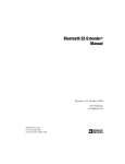
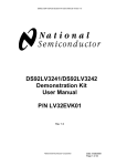
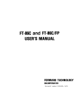
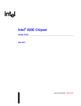
1
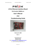
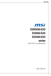
FPD-Link Evaluation Kit User Manual
FPD-Link Demonstration Kit
User Manual
P/N: FLINK3V10BT-TX/RX
Rev 0.6
Flat Panel Displays
National Semiconductor Corporation
Flat Panel Displays
LIT# FLINK3V10BT-TX/RX
-UM Rev 0.6
5/16/2008
Page 1 of 40
FPD-Link Evaluation Kit User Manual
Table of Contents
TABLE OF CONTENTS......................................................................................................................... 2
INTRODUCTION: ................................................................................................................................... 3
CONTENTS OF THE EVALUATION KIT: ............................................................................................. 4
FPD-LINK TYPICAL APPLICATION:.................................................................................................... 4
HOW TO SET UP THE EVALUATION KIT: .......................................................................................... 6
POWER CONNECTION:........................................................................................................................ 6
FPD-LINK TRANSMITTER BOARD DESCRIPTION:........................................................................... 7
CONFIGURATION SETTINGS FOR THE TX BOARD ..................................................................................... 8
TX LVTTL/LVCMOS AND LVDS PINOUT BY IDC CONNECTOR .............................................................. 9
BOM (BILL OF MATERIALS) TRANSMITTER PCB:.................................................................................. 10
RX FPD-LINK RECEIVER BOARD: ....................................................................................................12
CONFIGURATION SETTINGS FOR THE RX BOARD .................................................................................. 13
RX LVDS PINOUT AND LVTTL/LVCMOS BY IDC CONNECTOR ............................................................ 14
BOM (BILL OF MATERIALS) RECEIVER PCB:........................................................................................ 15
TYPICAL CONNECTION AND TEST EQUIPMENT ........................................................................... 17
TWO-WIRE SERIAL COMMUNICATION INTERFACE DESCRIPTION ............................................................ 19
LVDS DATA MAPPING ........................................................................................................................ 19
LVDS DATA MAPPING (CONT’D) ......................................................................................................... 20
LVDS DATA MAPPING (CONT’D) ......................................................................................................... 21
6-BIT, 8-BIT, 10-BIT APPLICATION ........................................................................................................ 22
TROUBLESHOOTING ......................................................................................................................... 24
ADDITIONAL INFORMATION ............................................................................................................. 25
EQUIPMENT REFERENCES ................................................................................................................... 25
APPENDIX ........................................................................................................................................... 26
National Semiconductor Corporation
Flat Panel Displays
LIT# FLINK3V10BT-TX/RX
-UM Rev 0.6
5/16/2008
Page 2 of 40
FPD-Link Evaluation Kit User Manual
Introduction:
National Semiconductor’s Flat Panel Displays FPD-Link evaluation kit contains a
Transmitter (Tx) board, a Receiver (Rx) board along with interfacing cables. This kit
will demonstrate the chipsets interfacing from test equipment or a graphics controller
using Low Voltage Differential Signaling (LVDS) to a receiver board. The
DS90C3201 and DS90C3202 are a 10-bit color Transmitter and Receiver chipset
designed to transmit data at clocks speeds from 8 to 135 MHz. Using a 10-bit color
depth system, the 30-bit RGB color produces over 1.07 billion colors to represent
high definition displays in their most natural color. The dual high speed LVDS
channels supports single pixel in-single pixel out and dual pixel in-dual pixel out
transmission modes.
The Transmitter board accepts LVTTL/LVCMOS RGB signals from the graphics
controller along with the clock signal. The LVDS Transmitter converts the
LVTTL/LVCMOS parallel lines into ten serialized LVDS data pairs plus a LVDS
clock. The serial data streams toggle at 3.5 times the clock rate. With an input clock
at 135 MHz, the maximum transmission rate of each LVDS line is 945Mbps, for an
aggregate throughput rate of 9.45Gbps. This allows the 10-bit color LVDS Receiver
to support resolutions up to HDTV.
The Receiver board accepts the LVDS serialized data streams plus clock and
converts the data back into parallel LVTTL/LVCMOS RGB signals and clock for the
panel timing controller.
The user needs to provide the proper RGB inputs and clock to the Transmitter and
also provide a proper interface from the Receiver output to the LCD panel or test
equipment. The transmitter and receiver boards can be used to evaluate device
parameters. A cable conversion board or harness scramble may be necessary
depending on type of cable/connector interface used. A power down feature is also
provided that reduces current draw when the link is not required. Other device
features and configurations can be programmed via 2-wire serial interface
National Semiconductor Corporation
Flat Panel Displays
LIT# FLINK3V10BT-TX/RX
-UM Rev 0.6
5/16/2008
Page 3 of 40
FPD-Link Evaluation Kit User Manual
Contents of the Evaluation Kit:
1) One Transmitter board with the DS90C3201
2) One Receiver board with the DS90C3202
3) One 50-pin IDC Flat Ribbon Cable
4) Evaluation Kit Documentation (this manual)
5) DS90C3201/3202 Datasheet
FPD-Link Typical Application:
Host
Display
(PC, Graphics Board, Video Processor)
(LCD Monitor, LCD TV, Digital TV)
(LVDS)
5 Pairs
DE
Pixel Data
Clock
Video
Source
HSYNC
5 Pairs
DS90C3201
FPD-Link
Transmitter
DE
DS90C3202
FPD-Link
Receiver
Pixel Data
Clock
Digital
Display
HSYNC
LVDS Clock
VSYNC
VSYNC
(LVCMOS/LVTTL)
(LVCMOS/LVTTL)
I2C
Figure 1a. Typical FPD-Link Application (Dual 30-bit RGB Color)
Video Processor Board
Digital
Input
TMDS Rx
Analog
Input
ADC
Video
Input
NTSC/PAL
Decoder
Digital Video
Processor /
Graphics Controller
FPD-Link Tx
(LVCMOS/LVTLL)
(LVDS)
LCD Monitor, LCD TV, Digital TV
FPD-Link Rx
(LVCMOS/LVTLL)
LCD Drivers
LCD Controller
-Timing
-Custom Logic
Figure 1b. Typical FPD-Link System Diagram
National Semiconductor Corporation
Flat Panel Displays
LIT# FLINK3V10BT-TX/RX
-UM Rev 0.6
5/16/2008
Page 4 of 40
FPD-Link Evaluation Kit User Manual
The diagrams above illustrate the use of the Chipset (Tx/Rx) in a Host to Flat Panel
Interface.
Chipsets support up to 18-bit, 24-bit, and 30-bit color depth TFT LCD Panels for any
VGA (640X480), SVGA (800X600), XGA (1024X768), WXGA (1280X768) SXGA
(1280X1024), SXGA+ (1400X1050), HDTV (1920X1080) resolutions.
Refer to the proper datasheet information on Chipsets (Tx/Rx) provided on each
board for more detailed information.
National Semiconductor Corporation
Flat Panel Displays
LIT# FLINK3V10BT-TX/RX
-UM Rev 0.6
5/16/2008
Page 5 of 40
FPD-Link Evaluation Kit User Manual
How to set up the Evaluation Kit:
The PCB routing for the Tx input pins (TxIN) have been laid out to accept incoming
data from IDC connectors. The TxOUT/RxIN interface uses a 50-pin IDC connector
through a IDC ribbon cable. Please follow these steps to set up the evaluation kit for
bench testing and performance measurements:
1) Connect one end of the 50-pin IDC cable to the transmitter board and the other
end to the receiver board. Longer lengths can be used.
2) Jumpers and switches have been configured at the factory; they should not
require any changes for operation of the chipset. See text on Configuration
settings for more details.
3) From the Video Decoder board, connect a flat cable (not supplied) to the
transmitter board and connect another flat cable (not supplied) from the receiver
board to the panel (Note: Refer Page 19 for suggested mapping schemes). A
scramble cable may be required.
4) Power for the Tx and Rx boards must be supplied externally through Power Jack
(VDD). Grounds for both boards are connected through Power Jack (VSS) (see
section below).
5) 2-wire serial interface for external EEPROM circuitry power is supplied through
Power jack (VDDE) and Ground for Power Jack (VSSE).
Power Connection:
The Transmitter and Receiver boards must be powered by supplying power
externally through J2 (VDD) and J3 (VSS) on Transmitter Board and J4 (VDD) and
J5 (VSS) on Receiver board. The maximum voltage that should ever be applied to
the FPD-Link Transmitter (DS90C3201) or Receiver (DS90C3202) VDD terminal is
+4V MAXIMUM. Optional EEPROM circuitry power is supplied through J4 (VDDE),
J5 (VSSE) or JP79 on Transmitter Board and J2 (VDDE), J3 (VSSE) or JP74 on
Receiver Board.
National Semiconductor Corporation
Flat Panel Displays
LIT# FLINK3V10BT-TX/RX
-UM Rev 0.6
5/16/2008
Page 6 of 40
FPD-Link Evaluation Kit User Manual
FPD-Link Transmitter Board Description:
JP1 to JP71 IDC connectors accepts 70 bits of LVTTL/LVCMOS RGB data along
with the clock input.
The FPD-Link Transmitter board is powered externally from the J2 and J3
connectors shown below. For the transmitter to be operational, the Power Down
(PWDN) switch on S2 must be set HIGH. Rising or falling edge reference clock is
also selected by S2 tied to HIGH (rising) or LOW (falling). Other device features and
configurations can be programmed via 2-wire serial interface through JP79.
The 50-pin IDC connector (J1) provides the interface for LVDS signals for the
Receiver board.
TDK EMC common-mode filters have been added in series on the LVDS signals for
high-frequency noise suppression.
g J4, J5
f J2, J3
Note: Vcc and Gnd MUST
be applied externally here
d
c LVDS OUTPUTS
d LVTTL/LVCMOS INTPUTS
e FUNCTION CONTROLS
f POWER SUPPLY
g 2-WIRE INTERFACE
d
c J1
JP1-JP21
JP22-JP49
JP72, JP73
JP50-JP71
d
S1
e
g
g JP79
g JP74
National Semiconductor Corporation
Flat Panel Displays
g
J6
e
S2
LIT# FLINK3V10BT-TX/RX
-UM Rev 0.6
5/16/2008
Page 7 of 40
FPD-Link Evaluation Kit User Manual
Configuration Settings for the Tx Board
Reference
WRITE PORT
(J74)
Description
2-wire Serial Interface
Write Protect
Open
Write Enabled
Closed
Write-Protected
Default setting for J74 is set Open (to VSS), Write Enabled.
S1: Transmitter Features Selection
Reference
Description
ENY
ENable “Y” Bank
(MODE1)
“ODD” Data Channels
ENX
ENable “X” Bank
(MODE0)
“EVEN” Data Channels
RFB
Rising or Falling Data
Strobe
PWDNB
PoWerDowN Bar
S2: External EEPROM Slave Address
Reference
Description
A2
Slave Address A2
(Default LOW)
A1
Slave Address A1
(Default LOW)
A0
Slave Address A0
(Default LOW)
L
Disabled
Disabled
Falling
(Default)
Powers
Down
H
Enabled
(Default)
Enabled
(Default)
Rising
S1
Operational
(Default)
S2
Default setting for S2 is set to all LOW, External EEPROM Slave Address
A[2:0]=000
National Semiconductor Corporation
Flat Panel Displays
LIT# FLINK3V10BT-TX/RX
-UM Rev 0.6
5/16/2008
Page 8 of 40
FPD-Link Evaluation Kit User Manual
Tx LVTTL/LVCMOS and LVDS Pinout by IDC Connector
The following two figures illustrate how the Tx inputs are mapped to the IDC
connectors J1P to JP71 (Note – labels are also printed on the demo boards). The
LVDS outputs for the 50-pin IDC (J1) connector pinout are also shown.
BANK X INPUTS
EVEN Data Channels
Pin
Symbol
No.
REF (Pin Name)
JP36 DIXA0 (TXEE0)
JP37 DIXA1 (TXEE1)
JP38 DIXA2 (TXEE2)
JP39 DIXA3 (TXEE3)
JP40 DIXA4 (TXEE4)
JP41 DIXA5 (TXEE5)
JP42 DIXA6 (TXEE6)
JP43 DIXB0 (TXED0)
JP44 DIXB1 (TXED1)
JP45 DIXB2 (TXED2)
JP46 DIXB3 (TXED3)
JP47 DIXB4 (TXED4)
JP48 DIXB5 (TXED5)
JP49 DIXB6 (TXED6)
JP50 DIXC0 (TXEC0)
JP51 DIXC1 (TXEC1)
JP52 DIXC2 (TXEC2)
JP53 DIXC3 (TXEC3)
JP54 DIXC4 (TXEC4)
JP55 DIXC5 (TXEC5)
JP56 DIXC6 (TXEC6)
JP57 DIXD0 (TXEB0)
JP58 DIXD1 (TXEB1)
JP59 DIXD2 (TXEB2)
JP60 DIXD3 (TXEB3)
JP61 DIXD4 (TXEB4)
JP62 DIXD5 (TXEB5)
JP63 DIXD6 (TXEB6)
JP64 DIXE0 (TXEA0)
JP65 DIXE1 (TXEA1)
JP66 DIXE2 (TXEA2)
JP67 DIXE3 (TXEA3)
JP68 DIXE4 (TXEA4)
JP69 DIXE5 (TXEA5)
JP70 DIXE6 (TXEA6)
BANK Y INPUTS
ODD Data Channels
Pin
Symbol
No.
REF (Pin Name)
DIYA0 (TXOE0)
JP1
DIYA1 (TXOE1)
JP2
DIYA2 (TXOE2)
JP3
DIYA3 (TXOE3)
JP4
DIYA4 (TXOE4)
JP5
DIYA5 (TXOE5)
JP6
DIYA6 (TXOE6)
JP7
DIYB0 (TXOD0)
JP8
DIYB1 (TXOD1)
JP9
JP10 DIYB2 (TXOD2)
JP11 DIYB3 (TXOD3)
JP12 DIYB4 (TXOD4)
JP13 DIYB5 (TXOD5)
JP14 DIYB6 (TXOD6)
JP15 DIYC0 (TXOC0)
JP16 DIYC1 (TXOC1)
JP17 DIYC2 (TXOC2)
JP18 DIYC3 (TXOC3)
JP19 DIYC4 (TXOC4)
JP20 DIYC5 (TXOC5)
JP21 DIYC6 (TXOC6)
JP22 DIYD0 (TXOB0)
JP23 DIYD1 (TXOB1)
JP24 DIYD2 (TXOB2)
JP25 DIYD3 (TXOB3)
JP26 DIYD4 (TXOB4)
JP27 DIYD5 (TXOB5)
JP28 DIYD6 (TXOB6)
JP29 DIYE0 (TXOA0)
JP30 DIYE1 (TXOA1)
JP31 DIYE2 (TXOA2)
JP32 DIYE3 (TXOA3)
JP33 DIYE4 (TXOA4)
JP34 DIYE5 (TXOA5)
JP35 DIYE6 (TXOA6)
JP71
TXCLK (TCLKIN)
LVDS OUTPUTS (J1)
ODD Data Channels
EVEN Data Channels
Pin
Symbol
Pin
Symbol
No.
REF (Pin Name)
No. REF (Pin Name)
XE - (TXEA-)
1
GND
26
YE - (TXOA-)
XE+ (TXEA+)
2
27
YE+ (TXOA+)
3
28
GND
4
GND
29
GND
XD - (TXEB-)
5
GND
30
YD - (TXOB-)
XD+ (TXEB+)
6
31
YD+ (TXOB+)
7
32
GND
8
GND
33
GND
XC - (TXEC-)
9
GND
34
YC - (TXOC-)
XC+ (TXEC+)
10
35
YC+ (TXOC+)
11
36
GND
12
GND
37
GND
XB - (TXED-)
13
GND
38
YB - (TXOD-)
XB+ (TXED+)
14
39
YB+ (TXOD+)
15
40
GND
16
GND
41
GND
XA - (TXEA-)
17
GND
42
YA - (TXOE-)
XA+ (TXEA+)
18
43
YA+ (TXOE+)
19
44
GND
20
GND
45
GND
21
GND
46
GND
CK - (TCLKOUT-)
22
47
GND
CK+ (TCLKOUT+)
23
48
GND
24
GND
49
GND
25
GND
50
GND
National Semiconductor Corporation
Flat Panel Displays
LIT# FLINK3V10BT-TX/RX
-UM Rev 0.6
5/16/2008
Page 9 of 40
FPD-Link Evaluation Kit User Manual
BOM (Bill of Materials) Transmitter PCB:
DS90C3201 Apps TX Demo Board
Bill Of Materials
February 18,2005
Item
Qty
Revision: 0c
17:00:16
Reference
Part
PCB Footprint
1
2
C1,C2
2.2uF
CAP/EIA-B
2
3
C3,C5,C40
0.1uF
CAP/HDC-1206
3
14
C4,C6,C7,C8,C9,C12,C21,
C22,C25,C28,C29,C38,C39,
C42
22uF
CAP/EIA-D
4
11
C10,C13,C16,C18,C19,C23,
C26,C30,C34,C36,C37
0.1uF
CAP/HDC-0603
5
11
C11,C14,C15,C17,C20,C24,
C27,C31,C32,C33,C35
0.01uF
CAP/HDC-0603
6
7
1
2
C41
F1,F2
0.01uF
32VDC1A
CAP/HDC-0805
Fuse/0603 (1608)
8
1
JP74
2-Pin Header
Header/2P
8a
1
JP1-JP21,
21X2-Pin Header
Header/42P
8b
1
JP22-JP49,
28X2-Pin Header
Header/56P
8c
1
JP50-JP71
22X2-Pin Header
Header/44P
9
4
JP72,JP73,JP77,JP78
3 pin Jumper
JUMP/3P
10
11
2
1
JP76,JP75
JP79
IDC2X2_Unshrouded
HEADER 4x1
CON/HDR-4P-A
HDR/4P
12
13
14
15
1
1
4
1
JP80
J1
J2,J3,J4,J5
J6
3 pin Jumper OPEN
IDC25X2_Shrouded
BANANA
DIP 4X2
JUMP/3P
IDC-50
CON/BANANA-S
DIP-8
16
11
L1,L2,L3,L4,L5,L6,L7,L8,
L9,L10,L11
Z = 90 ohm
20mm x 12mm
17
70
R1,R2,R3,R4,R5,R6,R7,R8,
R9,R10,R11,R12,R13,R14,
49.9ohmOPEN
RES/HDC-0201
National Semiconductor Corporation
Flat Panel Displays
LIT# FLINK3V10BT-TX/RX
-UM Rev 0.6
5/16/2008
Page 10 of 40
FPD-Link Evaluation Kit User Manual
R15,R16,R17,R18,R19,R20,
R21,R22,R23,R24,R25,R26,
R27,R28,R29,R30,R31,R32,
R33,R34,R35,R36,R37,R38,
R39,R40,R41,R42,R43,R44,
R45,R46,R47,R48,R49,R50,
R51,R52,R53,R54,R55,R56,
R57,R58,R59,R60,R61,R62,
R63,R64,R65,R66,R67,R68,
R69,R70
18
1
R71
49.9ohmOPEN
RES/HDC-0805
19
20
21
1
1
11
R72
R73
R74,R75,R76,R77,R78,R79,
R80,R81,R82,R83,R84
R85,R86,R87,R88,R89,R90,
R91,R92,R95,R96,R97
R93,R94,R98,R99,R100,
R101,R102,R103
R104,R105,R106,R107,R108,
R109,R110
10K OPEN
0 Ohm,0805 OPEN
100ohm,0805
RES/HDC-0805
RES/HDC-0805
RES/HDC-0805
22
11
0 Ohm,0402
RES/HDC-0402
23
8
4.75K
RES/HDC-0805
24
7
10K
RES/HDC-0805
25
1
S1
SW DIP-4
DIP-8
26
1
S2
SW DIP-3
DIP-6
27
1
U1
DS90C3201
128ldTQFP_VJX128A
National Semiconductor Corporation
Flat Panel Displays
LIT# FLINK3V10BT-TX/RX
-UM Rev 0.6
5/16/2008
Page 11 of 40
FPD-Link Evaluation Kit User Manual
Rx FPD-Link Receiver Board:
Reference JP1 to JP71 provides access to the 70 bit LVTTL/LVCMOS and clock
outputs.
The FPD-Link Receiver board is powered externally from the J4 and J5 connectors
shown below. For the receiver to be operational, the Power Down (PWDN) switch
on S2 must be set. Rising or falling edge reference clock is also selected by S2 tied
to HIGH (rising) or LOW (falling). Other device features and configurations can be
programmed via 2-wire serial interface interface through J74.
The 50-pin IDC connector (J1) provides the interface for LVDS signals for the
Receiver board.
TDK EMC common-mode filters have been added in series on the LVDS signals for
high-frequency noise suppression.
f J4, J5
g J2, J3
Note: Vcc and Gnd MUST
be applied externally here
c LVDS INPUTS
d LVTTL/LVCMOS OUTPUTS
e FUNCTION CONTROLS
f POWER SUPPLY
g 2-WIRE INTERFACE
d JP1-JP28
d JP29-JP50
c
J1
g JP72, JP73
g
d JP51-JP71
e S2
JP74
g
JP79
National Semiconductor Corporation
Flat Panel Displays
g e
J6
S1
LIT# FLINK3V10BT-TX/RX
-UM Rev 0.6
5/16/2008
Page 12 of 40
FPD-Link Evaluation Kit User Manual
Configuration Settings for the Rx Board
Reference
WRITE PORT
(J79)
Description
2-wire Serial Interface
Write Protect
Open
Write Enabled
Closed
Write-Protected
Default setting for J79 is set Open (to VSS), Write Enabled.
S2: Receiver Features Selection
Reference
Description
ENY
ENable “Y” Bank
(MODE1)
“ODD” Data Channels
ENX
ENable “X” Bank
(MODE0)
“EVEN” Data Channels
RFB
Rising or Falling Data
Strobe
PWDNB
PoWerDowN Bar
S2: External EEPROM Slave Address
Reference
Description
A2
Slave Address A2
(Default LOW)
A1
Slave Address A1
(Default LOW)
A0
Slave Address A0
(Default LOW)
L
Disabled
Disabled
Falling
(Default)
Powers
Down
H
Enabled
(Default)
Enabled
(Default)
Rising
S2
Operational
(Default)
S1
Default setting for S1 is set to all LOW, External EEPROM Slave Address
A[2:0]=000
National Semiconductor Corporation
Flat Panel Displays
LIT# FLINK3V10BT-TX/RX
-UM Rev 0.6
5/16/2008
Page 13 of 40
FPD-Link Evaluation Kit User Manual
Rx LVDS Pinout and LVTTL/LVCMOS by IDC Connector
The following two figures illustrate how the Rx outputs are mapped to the IDC
connectors JP1 to JP71 (Note – labels are also printed on the demo boards). The
LVDS 50-pin IDC connector (J1) pinout is also shown.
LVDS INPUTS (J1)
ODD Data Channels
EVEN Data Channels
Pin
Symbol
Pin
Symbol
No.
REF (Pin Name)
No.
REF (Pin Name)
XE - (RXEA-)
1
GND
26
YE - (RXOA-)
XE+ (RXEA+)
2
27
YE+ (RXOA+)
3
28
GND
4
GND
29
GND
XD - (RXEB-)
5
GND
30
YD - (RXOB-)
XD+ (RXEB+)
6
31
YD+ (RXOB+)
7
32
GND
8
GND
33
GND
XC - (RXEC-)
9
GND
34
YC - (RXOC-)
XC+ (RXEC+)
10
35
YC+ (RXOC+)
11
36
GND
12
GND
37
GND
XB - (RXED-)
13
GND
38
YB - (RXOD-)
XB+ (RXED+)
14
39
YB+ (RXOD+)
15
40
GND
16
GND
41
GND
XA - (RXEA-)
17
GND
42
YA - (RXOE-)
XA+ (RXEA+)
18
43
YA+ (RXOE+)
19
44
GND
20
GND
45
GND
21
GND
46
GND
CK - (RCLKIN-)
22
47
GND
CK+ (RCLKIN+)
23
48
GND
24
GND
49
GND
25
GND
50
GND
BANK X OUTPUTS
EVEN Data Channels
Pin
Symbol
No.
REF (Pin Name)
JP71 ROXA0 (RXEE0)
JP70 ROXA1 (RXEE1)
JP69 ROXA2 (RXEE2)
JP68 ROXA3 (RXEE3)
JP67 ROXA4 (RXEE4)
JP66 ROXA5 (RXEE5)
JP65 ROXA6 (RXEE6)
JP64 ROXB0 (RXED0)
JP63 ROXB1 (RXED1)
JP62 ROXB2 (RXED2)
JP61 ROXB3 (RXED3)
JP60 ROXB4 (RXED4)
JP59 ROXB5 (RXED5)
JP58 ROXB6 (RXED6)
JP57 ROXC0 (RXEC0)
JP56 ROXC1 (RXEC1)
JP55 ROXC2 (RXEC2)
JP54 ROXC3 (RXEC3)
JP53 ROXC4 (RXEC4)
JP52 ROXC5 (RXEC5)
JP51 ROXC6 (RXEC6)
JP50 ROXD0 (RXEB0)
JP49 ROXD1 (RXEB1)
JP48 ROXD2 (RXEB2)
JP47 ROXD3 (RXEB3)
JP46 ROXD4 (RXEB4)
JP45 ROXD5 (RXEB5)
JP44 ROXD6 (RXEB6)
JP42 ROXE0 (RXEA0)
JP41 ROXE1 (RXEA1)
JP40 ROXE2 (RXEA2)
JP39 ROXE3 (RXEA3)
JP38 ROXE4 (RXEA4)
JP37 ROXE5 (RXEA5)
JP36 ROXE6 (RXEA6)
BANK Y OUTPUTS
ODD Data Channels
Pin
Symbol
No.
REF (Pin Name)
JP35 ROYA0 (RXOE0)
JP34 ROYA1 (RXOE1)
JP33 ROYA2 (RXOE2)
JP32 ROYA3 (RXOE3)
JP31 ROYA4 (RXOE4)
JP30 ROYA5 (RXOE5)
JP29 ROYA6 (RXOE6)
JP28 ROYB0 (RXOD0)
JP27 ROYB1 (RXOD1)
JP26 ROYB2 (RXOD2)
JP25 ROYB3 (RXOD3)
JP24 ROYB4 (RXOD4)
JP23 ROYB5 (RXOD5)
JP22 ROYB6 (RXOD6)
JP21 ROYC0 (RXOC0)
JP20 ROYC1 (RXOC1)
JP19 ROYC2 (RXOC2)
JP18 ROYC3 (RXOC3)
JP17 ROYC4 (RXOC4)
JP16 ROYC5 (RXOC5)
JP15 ROYC6 (RXOC6)
JP14 ROYD0 (RXOB0)
JP13 ROYD1 (RXOB1)
JP12 ROYD2 (RXOB2)
JP11 ROYD3 (RXOB3)
JP10 ROYD4 (RXOB4)
ROYD5 (RXOB5)
JP9
ROYD6 (RXOB6)
JP8
ROYE0 (RXOA0)
JP7
ROYE1 (RXOA1)
JP6
ROYE2 (RXOA2)
JP5
ROYE3 (RXOA3)
JP4
ROYE4 (RXOA4)
JP3
ROYE5 (RXOA5)
JP2
ROYE6 (RXOA6)
JP1
JP43
RCLKOUT (RCLKOUT)
National Semiconductor Corporation
Flat Panel Displays
LIT# FLINK3V10BT-TX/RX
-UM Rev 0.6
5/16/2008
Page 14 of 40
FPD-Link Evaluation Kit User Manual
BOM (Bill of Materials) Receiver PCB:
DS90C3202 APPS RX Demo Board
Bill Of Materials
February 16,2005
Item
Qty
Revision: 1
13:19:22
Reference
Part
PCB Footprint
1
2
C4,C1
2.2uF
CAP/EIA-B
2
3
C2,C5,C108
0.1uF
CAP/HDC-1206
3
13
C3,C6,C35,C36,C41,C42,
C47,C52,C55,C62,C63,C64,
C110
22uF
CAP/EIA-D
4
71
C7,C8,C9,C10,C11,C12,C13,
C14,C15,C16,C17,C18,C19,
C20,C21,C22,C23,C24,C25,
C26,C27,C28,C29,C30,C31,
C32,C33,C34,C65,C66,C67,
C68,C69,C70,C71,C72,C73,
C74,C75,C76,C77,C78,C79,
C80,C81,C82,C83,C84,C85,
C86,C87,C88,C89,C90,C91,
C92,C93,C94,C95,C96,C97,
C98,C99,C100,C101,C102,
C103,C104,C105,C106,C107
open0402
CAP/HDC-0402
5
10
C37,C39,C43,C46,C48,C51,
C53,C57,C59,C61
0.01uF
CAP/HDC-0603
6
10
C38,C40,C44,C45,C49,C50,
C54,C56,C58,C60
0.1uF
CAP/HDC-0603
7
8
1
2
C109
F2,F1
0.01uF
32VDC1A
CAP/HDC-0805
Fuse/0603 (1608)
9
1
JP79
2-Pin Header
Header/2P
9a
1
JP1-JP28,
28X2-Pin Header
Header/56P
9b
1
JP29-JP50,
22X2-Pin Header
Header/44P
9c
1
JP51-JP71
21X2-Pin Header
Header/42P
10
11
4
1
JP72,JP73,JP75,JP76
JP74
3 pin Jumper
HEADER 4x1
JUMP/3P
HDR/4P
National Semiconductor Corporation
Flat Panel Displays
LIT# FLINK3V10BT-TX/RX
-UM Rev 0.6
5/16/2008
Page 15 of 40
FPD-Link Evaluation Kit User Manual
12
2
JP78,JP77
IDC2X2_Unshrouded
CON/HDR-4P-A
13
14
15
16
1
1
4
1
JP80
J1
J2,J3,J4,J5
J6
3 pin Jumper OPEN
IDC25X2_Shrouded
BANANA
DIP 4X2
JUMP/3P
IDC-50
CON/BANANA-S
DIP-8
17
11
Z = 90 ohm
20mm x 12mm
18
11
L1,L2,L3,L4,L5,L6,L7,L8,
L9,L10,L11
R1,R2,R3,R4,R5,R6,R7,R8,
R9,R10,R11
100ohm,0201
RES/HDC-0201
19
71
R12,R13,R14,R15,R16,R17,
R18,R19,R20,R21,R22,R23,
R24,R25,R26,R27,R28,R29,
R30,R31,R32,R33,R34,R35,
R36,R37,R38,R39,R40,R41,
R42,R43,R44,R45,R46,R47,
R48,R49,R50,R51,R52,R53,
R54,R55,R56,R57,R58,R59,
R60,R61,R62,R63,R64,R65,
R66,R67,R68,R69,R70,R71,
R72,R73,R74,R75,R76,R77,
R78,R79,R80,R81,R82
open,0201
RES/HDC-0201
20
21
22
1
1
10
10K OPEN
0 Ohm,0805 OPEN
0 Ohm,0402
RES/HDC-0805
RES/HDC-0805
RES/HDC-0402
23
8
4.75K
RES/HDC-0805
24
7
R83
R84
R85,R86,R87,R88,R89,R90,
R91,R92,R95,R96
R93,R94,R97,R98,R103,
R104,R105,R106
R99,R100,R101,R102,R107,
R108,R109
10K
RES/HDC-0805
25
1
S1
SW DIP-3
DIP-6
26
1
S2
SW DIP-4
DIP-8
27
1
U1
DS90C3202
128ldTQFP_VJX128A
National Semiconductor Corporation
Flat Panel Displays
LIT# FLINK3V10BT-TX/RX
-UM Rev 0.6
5/16/2008
Page 16 of 40
FPD-Link Evaluation Kit User Manual
Typical Connection and Test Equipment
The following is a list of typical test equipment that may be used to generate signals
for the TX inputs:
1) Digital Video Source – for generation of specific display timing such as Digital
Video Processor or Graphics Controller with digital RGB (LVTTL) output.
2) Astro Systems VG-835 - This video generator may be used for both video signal
sources for 10-bit Digital RGB and 10-bit LVDS.
3) Any other signal / video generator that generates the correct input levels as
specified in the datasheet.
4) Optional – Logic Analyzer or Oscilloscope
The following is a list of typically test equipment that may be used to monitor the
output signals from the RX:
1) LCD Display Panel which supports digital RGB (LVTTL) inputs.
2) Astro Systems VG-835 - This video generator may be used for both video signal
sources for 10-bit Digital RGB and 10-bit LVDS.
3) Optional – Logic Analyzer or Oscilloscope
4) Any SCOPE with 50 Ohm inputs or high impedance probes.
LVDS signals may be easily measured with high impedance / high bandwidth
differential probes such as the TEK P6247 or P6248 differential probes.
EEPROM Programming:
1) Future Designs, Inc. PC-I2C-KIT – This kit interfaces with IBM PC Compatible
and allows bi-directional communications with 2-wire serial interface peripherals.
The picture below shows a typical test set up using a Graphics Controller and LCD
Panel.
Transmitter
Board
Receiver
Board
LCD Panel
Digital RGB (TTL)
from Graphic
Contoller
LVDS Interface
Cable
Digital RGB
(TTL) to Panel
Contents of Demo Kit
Graphics Controller /
Video Processor Board
Figure 2. Typical FPD-Link Setup of LCD Panel Application
LIT# FLINK3V10BT-TX/RX
National Semiconductor Corporation
Flat Panel Displays
-UM Rev 0.6
5/16/2008
Page 17 of 40
FPD-Link Evaluation Kit User Manual
The picture below shows a typical test set up using a generator and scope.
Transmitter
Board
Receiver
Board
I2 C
Digital RGB
LVDS Interface
Cable
Digital RGB
PC Compatible
DIGITAL
VIDEO
GENERATOR
Logic Analyzer / Oscilloscope
Contents of Demo Kit
DIGITAL VIDEO GENERATOR
Digital Video Source
Figure 3. Typical FPD-Link Test Setup for Evaluation
National Semiconductor Corporation
Flat Panel Displays
LIT# FLINK3V10BT-TX/RX
-UM Rev 0.6
5/16/2008
Page 18 of 40
FPD-Link Evaluation Kit User Manual
Two-Wire Serial Communication Interface Description
Optional 2-wire serial interface programming allows fine tuning in development and
production environments. The DS90C3201/3202 is programmed through a 2-wire
serial interface. The 2-wire protocol features a serial clock (S2CLK) and a bidirectional serial data line (S2DATA). The DS90C3201/3202 operates as a slave on
the Serial Bus, so the S2CLK line is an input (no clock is generated by the
DS90C3201/3202). DS90C3201/3202 has a fixed 7-bit slave address, which is set to
7E’h (1111110’d) and 7C’h (1111100’d) for DS903201/3202 respectively. The PC
interface connector JP79 (Tx) and JP74 (Rx) is a 4 pin connector pin header for
interfacing with external EEPROM. J79 (Tx) / JP74 (Rx) is designed to interface
with the FDI PC-I2C kit through connector or an equivalent type as described.
Register values are programmed and stored in an onboard EEPROM via a two wire
serial interface and a PC compatible system. Upon power-up, default control
register values will be loaded into Tx/Rx. Otherwise, registers may be programmed
directly from the EEPROM into the Tx/Rx control registers via this same two wire
serial interface method.
LVDS Data Mapping
The FPD-Link Receiver which receives video data and timing through 10 pairs of
LVDS channels plus 1 LVDS clock to provide 30-bit dual color depth. The
Transmitter converts the LVTTL/LVCMOS parallel lines into ten serialized LVDS
data pairs plus a LVDS clock. The video data stream is then converted to
LVTTL/LVCMOS parallel data. The device accepts 10-bit / 8-bit / 6-bit single/dual
input data mapping as shown and also supports the JEIDA standard for 10-bit
LVDS.
Red
10-bit MSB
8-bit MSB*
6-bit MSB
LSB
Single
R9
R8
R7
R6
R5
R4
R3
R2
R1
R0
Dual
OR9 / ER9
OR8 / ER8
OR7 / ER7
OR6 / ER6
OR5 / ER5
OR4 / ER4
OR3 / ER3
OR2 / ER2
OR1 / ER1
OR0 / ER0
Single
G9
G8
G7
G6
G5
G4
G3
G2
G1
G0
Green
Dual
OG9 / EG9
OG8 / EG8
OG7 / EG7
OG6 / EG6
OG5 / EG5
OG4 / EG4
OG3 / EG3
OG2 / EG2
OG1 / EG1
OG0 / EG0
Blue
Single
B9
B8
B7
B6
B5
B4
B3
B2
B1
B0
Dual
OB9 / EB9
OB8 / EB8
OB7 / EB7
OB6 / EB6
OB5 / EB5
OB4 / EB4
OB3 / EB3
OB2 / EB2
OB1 / EB1
OB0 / EB0
Note: OR0-OR9, OG0-OG9, OB0-OB9 represents ODD pixel data,
ER0-OR9, EG0-OG9, EB0-OB9 represents EVEN pixel data.
*8-bit conventional color mapping
National Semiconductor Corporation
Flat Panel Displays
LIT# FLINK3V10BT-TX/RX
-UM Rev 0.6
5/16/2008
Page 19 of 40
FPD-Link Evaluation Kit User Manual
LVDS Data Mapping (Cont’d)
TCLK OUT /
RCLK IN
ODD
EVEN
V DIFF = 0V
V DIFF = 0V
6
5
4
3
2
1
0
TXOA /
RXOA
OG4
OR9
OR8
OR7
OR6
OR5
OR4
TXOB /
RXOB
OB5
OB4
OG9
OG8
OG7
OG6
OG5
TXOC /
RXOC
DE
VS
HS
OB9
OB8
OB7
OB6
TXOD /
RXOD
-----
OB3
OB2
OG3
OG2
OR3
OR2
TXOE /
RXOE
-----
OB1
OB0
OG1
OG0
OR1
OR0
TXEA /
RXEA
EG4
ER9
ER8
ER7
ER6
ER5
ER4
TXEB /
RXEB
EB5
EB4
EG9
EG8
EG7
EG6
EG5
TXEC /
RXEC
DE
-----
-----
EB9
EB8
EB7
EB6
TXED /
RXED
-----
EB3
EB2
EG3
EG2
ER3
ER2
TXEE /
RXEE
-----
EB1
EB0
EG1
EG0
ER1
ER0
COLOR BIT
MSB RGB9
RGB8
RGB7
RGB6
RGB5
RGB4
RGB3
RGB2
RGB1
LSB RGB0
ODD = 1st Pixel
EVEN = 2nd Pixel
Figure 1. Dual 10-Bit Input Mapping - JEIDA Compatible
TCLK OUT /
RCLK IN
V DIFF = 0V
V DIFF = 0V
6
5
4
3
2
1
0
TXOA /
RXOA
G4
R9
R8
R7
R6
R5
R4
TXOB /
RXOB
B5
B4
G9
G8
G7
G6
G5
TXOC /
RXOC
DE
VS
HS
B9
B8
B7
B6
TXOD /
RXOD
-----
B3
B2
G3
G2
R3
R2
TXOE /
RXOE
-----
B1
B0
G1
G0
R1
R0
COLOR BIT
MSB RGB9
RGB8
RGB7
RGB6
RGB5
RGB4
RGB3
RGB2
RGB1
LSB RGB0
Figure 2. Single 10-Bit Input Mapping - JEIDA Compatible
National Semiconductor Corporation
Flat Panel Displays
LIT# FLINK3V10BT-TX/RX
-UM Rev 0.6
5/16/2008
Page 20 of 40
FPD-Link Evaluation Kit User Manual
LVDS Data Mapping (Cont’d)
TCLK OUT/
RCLK IN
V DIFF = 0V
V DIFF = 0V
6
5
4
3
2
1
0
TXOA /
RXOA
G2
R7
R6
R5
R4
R3
R2
TXOB /
RXOB
B3
B2
G7
G6
G5
G4
G3
TXOC /
RXOC
DE
VS
HS
B7
B6
B5
B4
TXOD /
RXOD
-----
B1
B0
G1
G0
R1
R0
COLOR BIT
MSB RGB7
RGB6
RGB5
RGB4
RGB3
RGB2
RGB1
LSB RGB0
Figure 3a. Single 8-Bit Input Mapping – Conventional Color Mapping
TCLK OUT/
RCLK IN
V DIFF = 0V
V DIFF = 0V
6
5
4
3
2
1
0
TXOA /
RXOA
G0
R5
R4
R3
R2
R1
R0
TXOB /
RXOB
B1
B0
G5
G4
G3
G2
G1
TXOC /
RXOC
DE
VS
HS
B5
B4
B3
B2
TXOD /
RXOD
-----
B7
B6
G7
G6
R7
R6
COLOR BIT
LSB RGB7
RGB6
RGB5
RGB4
RGB3
RGB2
RGB1
MSB RGB0
Figure 3b. Single 8-Bit Input Mapping – Alternative Color Mapping
TCLK OUT/
RCLK IN
V DIFF = 0V
V DIFF = 0V
6
5
4
3
2
1
0
TXOA /
RXOA
G0
R5
R4
R3
R2
R1
R0
TXOB /
RXOB
B1
B0
G5
G4
G3
G2
G1
TXOC /
RXOC
DE
VS
HS
B5
B4
B3
B2
Figure 4. Single 6-Bit Input Mapping
National Semiconductor Corporation
Flat Panel Displays
LIT# FLINK3V10BT-TX/RX
-UM Rev 0.6
5/16/2008
Page 21 of 40
FPD-Link Evaluation Kit User Manual
6-bit, 8-bit, 10-bit Application
TXCLK OUT / RCLK IN
(Differential)
VDIFF= 0V
VDIFF= 0V
Previous
cycle
LVDS Data
Outputs / Inputs
Next
cycle
1 cycle
Bit6
Bit5
Bit4
Bit3
Bit2
Bit1
Bit0
Single LVDS Data Mapping
LVDS Bit
TXO/RXO
A0
A1
A2
A3
A4
A5
A6
B0
B1
B2
B3
B4
B5
B6
C0
C1
C2
C3
C4
C5
C6
D0
D1
D2
D3
D4
D5
D6
E0
E1
E2
E3
E4
E5
E6
1 x 6-bit
1 x 8-bit
1 x 8-bit*
1 x 10-bit
R0
R1
R2
R3
R4
R5
G0
G1
G2
G3
G4
G5
B0
B1
B2
B3
B4
B5
HS
VS
DE
R2
R3
R4
R5
R6
R7
G2
G3
G4
G5
G6
G7
B2
B3
B4
B5
B6
B7
HS
VS
DE
R0
R1
G0
G1
B0
B1
N/A
R0
R1
R2
R3
R4
R5
G0
G1
G2
G3
G4
G5
B0
B1
B2
B3
B4
B5
HS
VS
DE
R6
R7
G6
G7
B6
B7
N/A
R4
R5
R6
R7
R8
R9
G4
G5
G6
G7
G8
G9
B4
B5
B6
B7
B8
B9
HS
VS
DE
R2
R3
G2
G3
B2
B3
N/A
R0
R1
G0
G1
B0
B1
N/A
*Alternative Input Color Mapping
National Semiconductor Corporation
Flat Panel Displays
LIT# FLINK3V10BT-TX/RX
-UM Rev 0.6
5/16/2008
Page 22 of 40
FPD-Link Evaluation Kit User Manual
Dual LVDS Data Mapping
LVDS Bit
TXO/RXO
A0
A1
A2
A3
A4
A5
A6
B0
B1
B2
B3
B4
B5
B6
C0
C1
C2
C3
C4
C5
C6
D0
D1
D2
D3
D4
D5
D6
E0
E1
E2
E3
E4
E5
E6
2 x 6-bit
R0
R1
R2
R3
R4
R5
G0
G1
G2
G3
G4
G5
B0
B1
B2
B3
B4
B5
HS
VS
DE
2 x 8-bit
2 x 8-bit*
ODD Pixel Data
R2
R0
R3
R1
R4
R2
R5
R3
R6
R4
R7
R5
G2
G0
G3
G1
G4
G2
G5
G3
G6
G4
G7
G5
B2
B0
B3
B1
B4
B2
B5
B3
B6
B4
B7
B5
HS
HS
VS
VS
DE
DE
R0
R6
R1
R7
G0
G6
G1
G7
B0
B6
B1
B7
N/A
N/A
2 x 10-bit
LVDS Bit
R4
R5
R6
R7
R8
R9
G4
G5
G6
G7
G8
G9
B4
B5
B6
B7
B8
B9
HS
VS
DE
R2
R3
G2
G3
B2
B3
N/A
R0
R1
G0
G1
B0
B1
N/A
TXE/RXE
A0
A1
A2
A3
A4
A5
A6
B0
B1
B2
B3
B4
B5
B6
C0
C1
C2
C3
C4
C5
C6
D0
D1
D2
D3
D4
D5
D6
E0
E1
E2
E3
E4
E5
E6
2 x 6-bit
R0
R1
R2
R3
R4
R5
G0
G1
G2
G3
G4
G5
B0
B1
B2
B3
B4
B5
HS
VS
DE
2 x 8-bit
2 x 8-bit*
EVEN Pixel Data
R2
R0
R3
R1
R4
R2
R5
R3
R6
R4
R7
R5
G2
G0
G3
G1
G4
G2
G5
G3
G6
G4
G7
G5
B2
B0
B3
B1
B4
B2
B5
B3
B6
B4
B7
B5
HS
HS
VS
VS
DE
DE
R0
R6
R1
R7
G0
G6
G1
G7
B0
B6
B1
B7
N/A
N/A
*Alternative Input Color Mapping
National Semiconductor Corporation
Flat Panel Displays
LIT# FLINK3V10BT-TX/RX
-UM Rev 0.6
5/16/2008
Page 23 of 40
2 x 10-bit
R4
R5
R6
R7
R8
R9
G4
G5
G6
G7
G8
G9
B4
B5
B6
B7
B8
B9
HS
VS
DE
R2
R3
G2
G3
B2
B3
N/A
R0
R1
G0
G1
B0
B1
N/A
FPD-Link Evaluation Kit User Manual
Troubleshooting
If the demo boards are not performing properly, use the following as a guide for
quick solutions to potential problems. If the problem persists, please contact the
local Sales Representative for assistance.
QUICK CHECKS:
1. Check that Power and Ground are connected to both Tx AND Rx boards.
2. Check the supply voltage (typical 3.3V) and also current draw with both Tx and
Rx boards (should be about 100mA with clock and one data bit at 135MHz).
3. Verify input clock and input data signals meet requirements (VIL, VIH, tset,
thold), Also verify that data is strobed on the selected rising/falling (RFB pin)
edge of the clock.
4. Check that the Jumpers and Switches are set correctly.
5. Check that the cable is properly connected.
TROUBLESHOOTING CHART
Problem…
There is only the output clock.
There is no output data.
Solution…
Make sure the data is applied to the correct input pin.
Make sure data is valid at the input.
No output data and clock.
Make sure Power is on. Input data and clock are
active and connected correctly.
Power, ground, input data and
input clock are connected
correctly, but no outputs.
Make sure that the cable is secured to both demo
boards.
Check the Power Down pins of both boards and
make sure that the devices are enabled (/PD=Vcc) for
operation.
The devices are pulling more
than 1A of current.
Check for shorts in the cables connecting the TX and
RX boards.
After powering up the demo
boards, the power supply
reads less than 3V when it is
set to 3.3V.
Use a larger power supply that will provide enough
current for the demo boards, a 500mA power supply
is recommended.
National Semiconductor Corporation
Flat Panel Displays
LIT# FLINK3V10BT-TX/RX
-UM Rev 0.6
5/16/2008
Page 24 of 40
FPD-Link Evaluation Kit User Manual
Additional Information
For more information on FPD-Link Transmitters/Receivers, refer to the National’s
LVDS website at:
www.national.com/appinfo/fpd
Equipment References
Note: Please note that the following references are supplied only as a courtesy to
our valued customers. It is not intended to be an endorsement of any particular
equipment supplier.
Digital Video Pattern Generator – Astro Systems VG-835 (or equivalent):
Astro Systems
425 S. Victory Blvd. Suite A
Burbank, CA 91502
Phone: (818) 848-7722
Fax: (818) 848-7799
www.astro-systems.com
EEPROM Programming – FDI PC-I2C kit (or equivalent):
Future Designs, Inc.
2702 Triana Boulevard SW
Huntsville, AL 35805
Sales: (800) 278-0293
Information: (256) 883-1240
FAX: (256) 883-1241
www.teamfdi.com
Optional EMI Filters – TDK Chip Beads (or equivalent)
TDK Corporation of America
1740 Technology Drive, Suite 510
San Jose, CA 95110
Phone: (408) 437-9585
Fax: (408) 437-9591
www.component.tdk.com
Local U.S.A. direct contact:
Kazuhiko (Kevin) Umeda
Phone: (408) 467-5222
Email: [email protected]
National Semiconductor Corporation
Flat Panel Displays
LIT# FLINK3V10BT-TX/RX
-UM Rev 0.6
5/16/2008
Page 25 of 40
FPD-Link Evaluation Kit User Manual
Appendix
National Semiconductor Corporation
Flat Panel Displays
LIT# FLINK3V10BT-TX/RX
-UM Rev 0.6
5/16/2008
Page 26 of 40
FPD-Link Evaluation Kit User Manual
Tx PCB Schematic:
National Semiconductor Corporation
Flat Panel Displays
LIT# FLINK3V10BT-TX/RX
-UM Rev 0.6
5/16/2008
Page 27 of 40
FPD-Link Evaluation Kit User Manual
National Semiconductor Corporation
Flat Panel Displays
LIT# FLINK3V10BT-TX/RX
-UM Rev 0.6
5/16/2008
Page 28 of 40
FPD-Link Evaluation Kit User Manual
National Semiconductor Corporation
Flat Panel Displays
LIT# FLINK3V10BT-TX/RX
-UM Rev 0.6
5/16/2008
Page 29 of 40
FPD-Link Evaluation Kit User Manual
National Semiconductor Corporation
Flat Panel Displays
LIT# FLINK3V10BT-TX/RX
-UM Rev 0.6
5/16/2008
Page 30 of 40
FPD-Link Evaluation Kit User Manual
National Semiconductor Corporation
Flat Panel Displays
LIT# FLINK3V10BT-TX/RX
-UM Rev 0.6
5/16/2008
Page 31 of 40
FPD-Link Evaluation Kit User Manual
National Semiconductor Corporation
Flat Panel Displays
LIT# FLINK3V10BT-TX/RX
-UM Rev 0.6
5/16/2008
Page 32 of 40
FPD-Link Evaluation Kit User Manual
National Semiconductor Corporation
Flat Panel Displays
LIT# FLINK3V10BT-TX/RX
-UM Rev 0.6
5/16/2008
Page 33 of 40
FPD-Link Evaluation Kit User Manual
Rx PCB Schematic:
National Semiconductor Corporation
Flat Panel Displays
LIT# FLINK3V10BT-TX/RX
-UM Rev 0.6
5/16/2008
Page 34 of 40
FPD-Link Evaluation Kit User Manual
National Semiconductor Corporation
Flat Panel Displays
LIT# FLINK3V10BT-TX/RX
-UM Rev 0.6
5/16/2008
Page 35 of 40
FPD-Link Evaluation Kit User Manual
National Semiconductor Corporation
Flat Panel Displays
LIT# FLINK3V10BT-TX/RX
-UM Rev 0.6
5/16/2008
Page 36 of 40
FPD-Link Evaluation Kit User Manual
National Semiconductor Corporation
Flat Panel Displays
LIT# FLINK3V10BT-TX/RX
-UM Rev 0.6
5/16/2008
Page 37 of 40
FPD-Link Evaluation Kit User Manual
National Semiconductor Corporation
Flat Panel Displays
LIT# FLINK3V10BT-TX/RX
-UM Rev 0.6
5/16/2008
Page 38 of 40
FPD-Link Evaluation Kit User Manual
National Semiconductor Corporation
Flat Panel Displays
LIT# FLINK3V10BT-TX/RX
-UM Rev 0.6
5/16/2008
Page 39 of 40
FPD-Link Evaluation Kit User Manual
National Semiconductor Corporation
Flat Panel Displays
LIT# FLINK3V10BT-TX/RX
-UM Rev 0.6
5/16/2008
Page 40 of 40