1
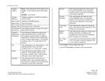
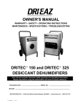
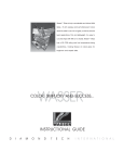
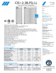
General Purpose Laboratory Freezer with Alarms 316981H01 • Rev. A 1 Table of Contents Introduction..........................................................................................................................................................3 Warning ........................................................................................................................................................3 Installation ..........................................................................................................................................................4 Unpacking ....................................................................................................................................................4 Visible Loss or Damage................................................................................................................................4 Concealed Loss or Damage ........................................................................................................................4 Packing List ..................................................................................................................................................5 Selecting a Location ....................................................................................................................................5 Leveling Unit ................................................................................................................................................5 Installing and Leveling Casters ....................................................................................................................6 Lamps ..........................................................................................................................................................6 Shelves ........................................................................................................................................................7 Electrical Connection ....................................................................................................................................8 Controls ..............................................................................................................................................................9 Panel Controls ..............................................................................................................................................9 Performance Characteristics ........................................................................................................................9 Displays and Features ..................................................................................................................................9 Key Switch............................................................................................................................................10 Temperature Display ............................................................................................................................10 Unit’s LED’s ..........................................................................................................................................10 Mode LED ............................................................................................................................................10 Cool LED ..............................................................................................................................................10 Alarm LED’s ..........................................................................................................................................10 Keypads ..............................................................................................................................................11 Interior Light Switch..............................................................................................................................11 Operation ..........................................................................................................................................................12 Temperature Set point .........................................................................................................................12 Units ....................................................................................................................................................13 High Alarm Set Point ............................................................................................................................13 Low Alarm Set Point ............................................................................................................................13 Alarm Silencing Menu ..........................................................................................................................13 Alarm Test Menu ..................................................................................................................................14 Control Mode ..............................................................................................................................................14 Loading ................................................................................................................................................14 Temperature Digression ......................................................................................................................15 Alarms ........................................................................................................................................................15 Over Temp Alarm..................................................................................................................................15 Under Temp Alarm................................................................................................................................15 Door Ajar Alarm (swinging door models only) ......................................................................................16 Power Loss Alarm ................................................................................................................................16 Alarm Silencing ....................................................................................................................................16 Alarm Test ............................................................................................................................................16 Remote Alarm Contacts ......................................................................................................................17 Open Sensor ........................................................................................................................................18 Battery Back Up ..........................................................................................................................................18 Controller Service (Menus) .........................................................................................................................19 Calibration Offset..................................................................................................................................19 Hold-Off Time ......................................................................................................................................19 Temperature Offset ……………………........................................................................................................20 Defrost Timer ..............................................................................................................................................20 Maintenance + Cleaning........................................................................................................................................21 Cabinet …………............................................................................................................................................21 Condenser ……………...................................................................................................................................21 Condensate Evaporator Pan .............................................................................................................................21 Troubleshooting ...................................................................................................................................................22 Replacement Parts...........................................................................................................................23 Wiring Diagrams................................................................................................................................................24 2 Introduction Warning Warnings alert you to a possibility of personal injury. Caution Cautions alert you to a possibility of damage to the equipment. Note Notes alert you to pertinent facts and conditions. Hot surfaces alert you to a possibility of personal injury if you come in contact with a surface during use or for a period of time after use. Caution Risk of electric shock. Warning These freezers are not approved for the storage of blood or blood products! Warning This product is not intended, nor can it be used, as a sterile or patient connected device. In addition, this apparatus is not designed for use in Class I,II or III locations as defined by the National Electrical Code, unless otherwise noted. Warning As a routine laboratory precaution, always wear safety glasses when working with this apparatus. DANGER: RISK OF CHILD ENTRAPMENT. BEFORE YOU THROW AWAY YOUR OLD FREEZER: • TAKE OFF DOORS • LEAVE THE SHELVES IN PLACE SO THAT CHILDREN MAY NOT EASILY CLIMB INTO UNIT. Warning High voltage is supplied to PC board when key switch is OFF. This manual is intended to provide installation and operating instructions for your general purpose laboratory freezer. Your satisfaction and safety are important to us. A complete understanding of this unit is necessary to attain these objectives. As the ultimate user of this apparatus, it is your responsibility to understand its proper function and operational characteristics. This instruction manual should be thoroughly read and all operators given adequate training before attempting to place this unit in service. Awareness of the stated cautions and warnings, and compliance with recommended operating parameters together with maintenance requirements - are important for safe and satisfactory operation. The unit should be used for its intended application; alterations or modifications will void the Warranty. Warning • This manual must be carefully read and thoroughly understood before operating the unit. Failure to follow directions or precautionary measures could result in serious adverse effects. • This equipment must be used only as specified in these instructions. If used in a manner other than as specified, the protection provided by the equipment may be impaired. • This equipment is intended for indoor use only. • This equipment must be earth grounded for safe operation. • Disconnect unit line cord from power source before performing any servicing or maintenance. 3 Installation Unpacking Save all packing material if apparatus is received damaged. This merchandise was carefully packed and thoroughly inspected before leaving our factory. Responsibility for its safe delivery was assumed by the carrier upon acceptance of the shipment; therefore, claims for loss or damage sustained in transit must be made upon the carrier by the recipient as follows: Visible Loss or Damage Note any external evidence of loss or damage on the freight bill, or express receipt, and have it signed by the carrier’s agent. Failure to adequately describe such external evidence of loss or damage may result in the carrier’s refusing to honor your damage claim. The carrier will supply the form required to file such a claim. Concealed Loss or Damage Concealed loss or damage refers to loss or damage, which does not become apparent until the merchandise has been unpacked and inspected. Should either occur, make a written request to the carrier’s agent within 15 days of the delivery date; then file a claim with the carrier since the damage is the carrier’s responsibility. If you follow the above instructions carefully, we will guarantee our full support of your claim to be compensated for loss from concealed damage. DO NOT – FOR ANY REASON – RETURN THIS UNIT WITHOUT FIRST OBTAINING AUTHORIZATION 4 INSTALLATION Packing List The following items are located inside the freezer chamber. If any of the following items are not present, report the missing item to your local representative. • Instruction Manual • Warranty information • Door Lock and Power Switch Keys • Shelves and Casters Selecting a Location Choose a location for the freezer that will provide at least three inches of clearance between the cabinet and any adjacent vertical surface at the sides and rear. At least 12 inches of clearance is needed above the unit for air circulation. Appropriate electrical power must be available. Locate the freezer within 6 feet of the power outlet so that no extension cord is required. Note The freezer must be level in order to provide adequate condensation drainage as well as proper door alignment and operation. The freezer should be in its final operating location and set so that it is firmly positioned on the floor. Leveling the Unit The freezer must be level in order to provide adequate condensation drainage as well as proper door alignment and operation. The freezer should be in its final operating location and set so that it is firmly positioned on the floor. 5 INSTALLATION Caution If the unit was tilted in excess of 30 degrees, level it and do not apply electrical power for a minimum of 12 hours. Installing and Leveling Casters Freezers come with four casters, which thread into the base of the unit, one in each corner. Remove the leveling screws from the unit and use the wrench provided to thread the casters completely into the base of the unit. See Figure 1. Tighten using wrench provided Freezer Base Thread casters directly into base at four corners Figure 1 Caution Improperly installed lamps may cause damage to the lighting circuit. 6 Lamps Prior to applying power to the unit, verify that all of the internal lamps are properly installed and fully engaged in the lamp holders. INSTALLATION Shelves Shipped inside each cabinet are shelves packed in plastic and a bag of shelf supports. Note Note the numbers on the pilasters. Place supports on the same numbers on each pilaster to ensure the shelf will be level. Two different shelf supports are provided. The shorter tab length version is used on the front of the shelf. Shelf spacing is adjustable to suit user requirements. Insert four shelf supports for each shelf into the pilasters as shown. Place the shelf on the pilasters as shown in Fig’s 2 and 3. Replacement shelves are available individually. Call Technical Service at 8004384851 for shelf part numbers. Proper shelf orientation is illustrated in Figures 2 & 3. Figure 2 Figure 3 - Place shelves at desired height on four shelf supports. 7 INSTALLATION Warning Insufficient line voltage is often the cause of compressor start-up failure. It is strongly recommended that a dedicated circuit, conforming to the National Electrical Code, Article 440, be used for powering the freezer. Caution Be sure that the power supply is the same voltage that is specified on the freezer's data plate. Warning For personal safety this unit must be properly grounded. Warning DO NOT under any circumstances cut or remove the third (ground) prong from the power cord. DO NOT use a two-prong adapter plug. Warning Do not use an extension cord. Use of an ungrounded cord or an overloaded circuit VOIDS the compressor warranty. 8 Electrical Connection The frequency and nominal voltage requirements for the unit are specified on the data plate, which is located on the interiors upper left side. Only plug the unit into a power source that meets these requirements. Low line voltage is often the cause of service complaints. With the unit running, check that the line voltage is within ±10% of that specified on the data plate. The power cord on most units has a three prong (grounding) plug (NEMA 5-15P). This plug mates with a standard three prong (grounding) wall receptacle (NEMA 5-15R) to minimize the potential of an electrical shock hazard. Where necessary models are equipped with a linecord and NEMA 5-20P plug. This plug requires a NEMA 5-20R receptacle. Where necessary models are equiped with a linecord and NEMA L1420P plug. This plug requires a L1420R receptacle. The customer should have the wall receptacle and circuit checked by a qualified electrician to verify the receptacle is properly grounded and meets power requirements specified on the data plate. Where a two prong wall receptacle is encountered, it is the personal responsibility and obligation of the user to have it replaced with a properly grounded three prong receptacle. During compressor start-up, the unit will momentarily draw more current than under normal running conditions. To avoid nuisance tripping of circuit breakers, it may be necessary to install an HACR rated breaker. Controls Panel Controls The control system provides both audible and visual indication of alarm conditions in an easy to read display format. In addition, there are two sets of contacts available for remote alarm switching. Temperature and alarm set points are directly entered in °C or °F. Before operation, it is necessary to become familiar with the freezer controls. All the freezer controls are located on the header panel. A layout of the controller and LED’s are given below. Performance Characteristics Temperature Range: -30.0° to 0°C (-22.0° to 32.0°F) Temperature Stability: ±3°C Warning High voltage is supplied to PC board when key switch is OFF. Displays and Features On the right side of the header panel is the key switch. The key switch has three positions, OFF (O), Set-up (I) and Alarm Enable ( ). With the freezer plugged in and the key switch in the OFF position, the displays and 9 CONTROLS refrigeration system are off. The control board remains energized in order to supply a charge to the battery. Key Switch Note The key can be removed in the Off or the Alarm Enabled position. Turning the key switch to the middle position energizes the circulation fans and the controller display. When the controller is in the Set-Up mode, the menu items can be set to the desired values. See Controller Set Up for a description of each. Once all menu items are set, the freezer should then be switched to the Alarm Enabled position. While in the Alarm Enabled position, the menu items can be viewed but not changed. The key can be removed to secure the values entered. Temperature Display The temperature display indicates chamber temperature while in the control mode of operation and menu titles and values while entering menu items (see Menus). Units LED’S The temperature display indicates chamber temperature in both °C and °F. The current units are indicated by the corresponding LED located to the right of the temperature display. Mode LED The Mode LED is lit when the Menu keypad has been pressed. It indicates to the user that the controller is in the menu selection mode. Cool LED Caution Alarms will only activate with the key in the Alarm Enabled position. The Cool LED is lit when the controller calls for cooling. When this LED comes on the compressor should energize. Alarm LED’S Door Ajar - This LED is illuminated when a freezer door(s) is opened. Over Temp – Indicates the current chamber temperature exceeds the high alarm temperature set point. Under Temp – Indicates the current chamber temperature is lower than the low alarm temperature set point. Power Out – Indicates AC power to the freezer is disrupted. Alarm Test – Indicates the controller is running an alarm test. 10 CONTROLS Keypads Menu Keypad – Pressing the Menu keypad enters the controller into the menu selection mode, designated by the illumination of the MODE LED. Repeatedly pressing the Menu keypad cycles through the list of menu items (see Menus). After the final menu, the controller returns to the control mode and the MODE LED turns off. Up Arrow Keypad – Increases or changes menu values. Down Arrow Keypad - Decreases or changes menu values. Interior Light Switch The interior lamp(s) is controlled by a rocker switch located on the control panel. This light may be operated any time the cabinet power is turned on at the keyed power switch. If the interior lamp fails, replace with the same size and wattage lamp. DO NOT USE REDUCED WATTAGE LAMPS. The reduced wattage lamps generally fail to light below 60°F (15°C). Be sure that lamps are properly installed. Failure to install lamps properly may cause damage to the lighting circuit. • Solid door models – The control panel light switch controls the interior light when the doors are open. 11 Operation Note The “Pout” display is a normal occurrence when power is first applied to the controller. Press any key to clear it. The freezer is started by inserting the power switch key, which is found inside the unit, into the key switch. Turn the key to the middle (set up) position. The internal fans will start and the display will flash between Pout and the current chamber temperature. The “Pout” (power out) display indicates to the user that the controller has sensed a low voltage condition. This condition is normal during any start-up. See the Alarms section for details on the Pout message. Press any keypad to clear the Pout. Controller Set-Up (Menus) During normal operation, the freezer temperature is displayed on the 4-character display. The compressor cycles on and off to control the chamber temperature between -30.0° and 0.0°C (-22.0 to 32.0°F), selectable by the user. The temperature set point, high and low alarm set-points, units and display offset can be changed while the key switch is in the set-up (middle) position. These values can be viewed but not changed with the key switch is in the alarm enabled position. The menu options are explained in the following sections. There are 8 menus to select from, each can be accessed by pressing the Menu keypad. Pressing the Menu key- pad once brings up the first menu, which is the temperature set point. The displays initially flash SP followed by the last set temperature value. Pressing the Menu key- pad again, accepts the value and displays the next menu, units select (CF). Each menu value is entered this way. The menus can be changed only while the key switch is in the set up (I) position. They can be viewed but not changed while the key switch is in the alarm enable( ) position. The individual menus are described below. Temperature Set point • • 12 Temperature Set Point is factory preset at -30.0°C (-22.0°F). Adjusting the temperature Set Point is not recommended. Temperature Set Point (SP) – Adjustable from -30.0 to 0.0°C or -22.0 to 32.0°F. Use the Up/Down Arrow keypads to change the temperature and the Menu keypad to enter the value and switch to the next menu. OPERATION Units • Units select (C,F) – Selects the desired temperature display units in °C or °F. Use the Up Arrow keypad to change the units from C to F. Use the Down Arrow keypad to switch from F to C. Press the Menu keypad to enter the units value and continue. The appropriate units LED will indicate the selected units. High Alarm Set Point • High Alarm Set Point (AH) – Use the Up/Down Arrow keypad to adjust the value that triggers a high alarm condition if the chamber temperature rises above it. The high alarm temperature range is from 3.5°C (6.3°F) above the Temperature Set Point to 37.0°C (98.6°F). • Factory preset at 14.0°C (6.8°F). NOTE: The High and Low alarm set points can be adjusted to be within 3.5°C (6.3°F) of one another and no closer. Low Alarm Set Point • • Low Alarm Set Point (AL) – Use the Up/Down Arrow keypad to adjust the value that triggers a low alarm condition. The low alarm condition occurs when the actual chamber temperature drops below the Low Alarm Set Point. The low alarm range is from 3.5°C (6.3°F) below the Temperature Set Point to -36.0°C (-32.8°F). Factory preset at -33.0°C (27.4°F). Alarm Silencing Menu • Alarm Silencing (AS) – During an alarm condition, while the key switch is in the Alarm Enable Mode, this menu allows the user to silence the audible alarm for 5 minutes. After the AS stops flashing, the display will show n, press the Up Arrow keypad to change the display to y. Press the Menu Keypad and the audible alarm will turn off for 5 minutes. 13 OPERATION Alarm Test Menu • Alarm Test (At) –Use the Up Arrow keypad to change the n to H. By subsequently pressing the Menu Keypad the controller will perform a High Alarm Test (see Alarm Test in Alarms section). Use the Down Arrow Keypad to change the display to L. Pressing the Menu Keypad will activate the Low Alarm Test. Pressing the Menu Keypad while the display shows n returns the unit to control mode (MODE LED off). NOTE: While in any of the above menu options, the controller will wait 15 seconds for a new value to be entered. If there is no keypad activity within 15-seconds, the freezer will automatically shift to the Control Mode and the Mode LED will turn off. Control Mode The Control Mode of operation is indicated when the Mode LED is OFF. With the desired temperature set point and alarm values entered, the freezer will then begin to control to the set temperature. There is a time delay between compressor activations. This delay begins the moment the controller is energized or the moment the compressor turns off during normal operation. The delay is added to provide time for the system pressure to drop before the compressor tries to start again. Loading Follow the guidelines below in order to provide optimal freezer performance: 14 • When loading with critical samples, verify all alarms and features are operating properly. • Space samples uniformly in the chamber. • Keep samples away from the back wall that may obstruct airflow. • It is best to load the freezer from bottom to top. Keeping the area next to the air intake and exhaust clear will help assure proper airflow. OPERATION Temperature Digression By pressing the Increase keypad while the freezer is in the Control Mode, the display will show the warmest temperature recorded since the unit was energized or the digression values were reset. Pressing the Decrease keypad will display the coldest temperature recorded since the unit was energized or the digression values were reset. To reset the temperature digression values, simply press the Increase and Decrease keypads at the same time. The display will show Clr, indicating the controller will begin recording new warm and cold digressions once more. Alarms Freezers are equipped with audible and visual alarms. They also feature remote alarm contacts. The key switch must be in the Alarm Enable position for the audible alarm and remote alarm contacts to activate. Alarm messages are shown on both the temperature display and in the row of Alarm LED’s located above the temperature display. The following conditions will trigger an alarm: Note The Over Temp Alarm is disabled for a period of 2 hours after the defrost cycle begins to remove frost buildup at the refrigeration unit and allow the temperature to stabilize. • Chamber temperature is greater than the high alarm set point. • Chamber temperature is less than the low alarm set point. • Door has been left open for 3 minutes or more. • AC power has been interrupted to the freezer. • Open sensor Over Temp Alarm If the freezer chamber temperature rises above the High Alarm Set Point, the display will alternately flash the freezer chamber temperature and “HigH”. The Over Temp LED will be lit, the audible alarm will sound and the remote contacts will change state. Under Temp Alarm If the freezer chamber temperature falls below the Low Alarm Set Point, the display will alternately flash the freezer chamber temperature and “Lo”. The Under Temp LED will be lit, the audible alarm will sound and the remote contacts will change state. 15 OPERATION Door Ajar Alarm (swinging door models only) When a swinging door is opened, the Door Ajar LED lights and the display alternately flashes between the freezer temperature and “door”. If a door is opened for 3 minutes, the audible alarm will sound and the remote alarm contacts change state. Power Out Alarm When AC power is lost, the display will alternately flash between the current freezer temperature and “Pout”, the Power Out LED will light, the audible alarm will sound and the remote contacts will change state. When power is restored, the display will continue flashing the “Pout” message until it is cleared by the user by pressing any of the keypads. Alarm Silencing The audible alarm can be silenced by deactivating it at the Alarm Silence Menu (see section earlier in this manual). The audible alarm will silence for 5 minutes. It will sound again at the end of the 5 minutes if the alarm condition persists. Alarm silencing does not affect the visual alarms. Alarm Test The Alarm Test feature is used to verify proper alarm operation by simulating an increase or decrease in chamber temperature. The alarm test function will work for any value of high or low alarm set points. With the key switch in the Set Up Position the remote and audible alarms are not activated during an alarm test, as is the case in an actual alarm condition. Note The key switch should be in the Alarm Enabled Position in order to test all alarm features 16 The procedure for testing the alarms is simple. Press the Menu Keypad repeatedly until the display shows At (alarm test). Momentarily, the display will change to n. Press the Up Arrow Keypad to change the display from n to H in order to perform a high alarm test. With the display showing H, press the Menu Keypad again and the temperature display will begin to rise until it reaches the High Alarm Set Point. Once the set point is reached, both audible and visual alarms should be activated (with the key switch in alarm enable position) and the remote alarm contacts should change state. To perform a low alarm OPERATION test, simply press the Down Arrow Keypad when the display shows n. The display will then show L. Press the Menu Keypad again in order to activate the low alarm test. Remote Alarm Contacts In addition to the audible and visual alarms, there are two sets of remote contacts on the side of the header panel, which change state during an alarm. The upper set of contacts provides both normally open and normally closed switching. Remote Alarm Contacts Figure 4 Note Remote alarm contacts are active only with the key switch in the Alarm Enabled position. All contacts are capable of switching up to 24 volts AC/DC @ 2 amps. The common (C) and normally closed (NC) contacts open during an alarm. The common (C) and normally open (NO) contacts close during and alarm. The contacts for the Deluxe Remote Alarm are normally closed and open during and alarm. Figure 4 shows the location of the remote and deluxe alarm contacts. 17 OPERATION Open Sensor Caution Moving location of control sensor voids warranty When the controller is unable to read from the sensor, the display will show SnSr, indicating that a sensor error exists The display will alternately flash SnSr and HigH. The audible alarm will sound, the remote alarm contacts will change state and the over temp LED will illuminate. Battery Back Up The freezers are supplied with a rechargeable battery backup. The battery will continue to supply power to the controller and alarm features in the event of a power outage. A fully charged battery can continue powering the controller for up to 8 hours during a power failure. The battery is recharged by the temperature controller during normal operation. The battery should be checked every six months and replaced when necessary (see Replacement Parts). Check the battery by unplugging the freezer and monitoring the controller operation. If the controller does not properly activate the alarm features for 2 hours, replace the battery. Under normal operation, the battery backup should last up to four years or 200 charge/discharge cycles. 18 OPERATION Controller Service (Menus) The two final menu items, calibration offset and hold-off time (oS and Ho), are not accessible from the main menu. In order to view and/or change them, the Menu keypad must be pressed and held for 5 seconds. The calibration offset (oS) menu will then be displayed briefly followed by the most recent offset value. Calibration Offset • Display Offset (oS) – Use the Up/Down Arrow keypads to adjust the offset value. Adjustable to +/- 5.0°C (+/- 9.0°F). This value is added to the temperature display to correct for differences between actual and displayed chamber temperature. See Calibration… for details. Press the Menu keypad to enter the new value or to continue to the next menu. Hold-Off Time • Hold-Off (Ho) – Use the Up/Down Arrow keypads to adjust the Hold-Off time in minutes. Adjustable from 3 to 10. This value represents the delay time between compressor activations. Increasing the Hold-Off time can help prevent evaporator freezeup by increasing the defrost cycle time. Press the Menu keypad to enter the new value and return to temperature control mode. 19 OPERATION Temperature Offset Caution INCREASING the offset value DECREASES the temperature at which the system controls. If the offset is inadvertently set too high, the chamber temperature will drop below desired temperature and can lead to evaporator freeze-up. In the event the freezer needs to be calibrated, a simple routine is available to adjust the display and control point to a referenced standard. To set a temperature off- set while in the Control Mode (mode LED off), simply press and hold the Menu key for 5 seconds. The display will flash oS followed by the last temperature offset value. The factory setting is 0.0. To change the offset value, press the Increase or Decrease keypad to the value which when algebraically added to the last displayed temperature, will agree with the reference temperature. Next, press the Menu key until the Mode LED turns off. For Example: The display indicates -30°C but a reference thermometer in the freezer chamber indicates -28°C. The operator presses and holds the Menu KEY until the display shows (oS) offset, then the value. Change the value from 0.0 to 2.0. The Menu key is then pressed repeatedly until the Mode LED turns off. Now the display indicates a chamber temperature of -28.0°C (approx.) and the controller begins to cool to the desired temperature of 30.0°C. Allow an additional 30 to 40 minutes for the freezer to again stabilize. If the display is still inaccurate, repeat the calibration procedure. Defrost Timer All freezers come equipped with a 24 hour defrost timer. The timer will trigger a defrost cycle 4 times per 24 hours. When a defrost cycle begins, the display will alternately flash dfSt and the current chamber temperature. The defrost cycle typically lasts for 30 minutes or so, depending on the last freezer temperature. When a defrost cycle begins, the High Alarm is disabled for a period of 2 hours. This is to provide enough time for the defrost cycle to occur and for the freezer temperature to drop below the high alarm set point after the defrost period has ended. 20 Maintenance + Cleaning Cabinet Caution When servicing the unit, disconnect plug from the electrical power source Caution Do not use any type of abrasive such as steel wool or fluids, such as gasoline, Naptha or paint thinner, that could be harmful to plastic materials, door gasket and/or painted surfaces for cleaning. The cabinet interior should be cleaned frequently. Any spilled liquid should be wiped off immediately. Stains resulting from some spills can be permanent if not quickly removed. The cabinet exterior should be cleaned occasionally. A mild detergent and lukewarm water or a solution of bicarbonate of soda (1 tablespoon per gallon of water) is recommended for cleaning the interior and exterior of the cabinet. All surfaces should be rinsed and thoroughly dried. Condenser The condenser is located in front of the compressor fan, which is behind the base grill. The condenser should be cleaned before becoming clogged with dirt/dust. Construction or other dirt causing environments may significantly increase the required frequency. The condenser should be cleaned at least once a year. Condensate Evaporator Pan The condensate evaporator pan is located behind the compressor fan, which is behind the base grill. This pan should be cleaned at least once a year to prevent foul odors and operate efficiently. Vacuum clean if dry, or sponge clean with soapy water. 21 Troubleshooting This table is intended to assist in resolving user-correctable Freezer problems by relating symptoms to their likely causes. If service beyond the scope of this table is required, contact Service Division at 1-800438-4851. Symptom Does Not Run Probable Cause Unit Unplugged Action Plug in Unit Blown fuse or tripped circuit breaker Check fuse or circuit breaker at breaker box Frost buildup on refrigeration coils. Turn unit off and allow it to defrost. Freezer over-loaded. Remove contents from top shelf of unit. Clicking Sound The compressor is equipped with a thermal protector. This device shuts off the compressor when it becomes too hot. A clicking sound occurring about every 30 seconds indicates this protector is working Disconnect power and allow unit to sit for about an hour, then retry. If condition persists, call for service. Insufficient Cooling Set temp is too high Reduce temperature setting, verify Cool LED turns on in 3 minutes. Condenser coil dirty Clean condenser coil with a vacuum cleaner Unit frosted Defrost unit Offset (oS) value is too low. Increase offset value. Defrost mode activated. Allow enough time for defrost mode to end (2 hours maximum). Runs Continuously 22 Replacement Parts Replacements for Laboratory Freezer parts serviceable by the user may be ordered, by part number, from Service at 1800-438-4851. Solid State Relay(K2) 25A 88616 Solid State Relay(K2) 45A 316734H01 Magnetic Relay (K1) SPST Magnetic Relay (K1) DPDT Alarm Version Temperature Controller Shelf Support (Front) Shelf Support (Rear) Chart Recorder Manual Rechargeable Battery Temperature Sensor 102259 102260 316637H01 103264 103265 316983H01 104711 104163 23 Wiring Diagrams 115 VAC WHT BLK L1 R1 FREEZER LIGHT BLU WHT BLU TO TEMP CONTROLLER YEL EVAPORATOR FAN CONTROL DEFROST SWITCH 2 YEL PRPL WHT BLU EVAPORATOR FANS (2) FACE HEATERS (2) BLK ORN DEFROST TIMER CUT-OUT COIL BLK DEFROST SWITCH 1 DEFROST HEATER ORG WHT RED DEFROST LIMIT CONTROL R2 COMPRESSOR MOTOR CONDENSER FAN(S) 12 VDC BATTERY CONTROL ON/OFF CIRCUIT L1 DEFROST INPUT N AC TEMP CONTROLLER INPUT FROM DOOR SWITCH KEY SWITCH ALARM ENABLE 12 V DC 12 V DC 6-PIN INPUT HEADER 6 PIN OUTPUT HEADER 24 R2 Compressor Relay R1 SYSTEM RELAY N Wiring Diagrams RED Hinged Solid Door Models 230 VAC WHT L1 R1 BLK FREEZER LIGHT BLU N WHT L2 R1 TO TEMP CONTROLLER YEL EVAPORATOR FAN CONTROL DEFROST SWITCH 2 YEL PRPL WHT BLU BLU EVAPORATOR FANS (2) FACE HEATERS (2) BLK ORN DEFROST TIMER CUT-OUT COIL BLK DEFROST SWITCH 1 ORG DEFROST HEATER WHT RED DEFROST LIMIT CONTROL R3 DEFROST R2 COMPRESSOR MOTOR 12 VDC BATTERY CONTROL ON/OFF CIRCUIT N L1 AC TEMP CONTROLLER INPUT FROM DEFROST TIMER CONDENSER FANS (2) INPUT FROM DOOR SWITCH A C KEY SWITCH ALARM ENABLE 12 V DC 12 V DC 6-PIN INPUT HEADER 6 PIN OUTPUT HEADER R2 Compressor Relay R1 SYSTEM RELAY 25