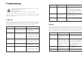
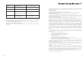
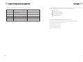
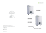
1
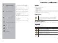
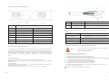
Growatt 8000TL-US
Growatt 9000TL-US
Growatt 10000TL-US
Growatt 11000TL-US
Installation
Shenzhen Growatt New Energy Technology CO.,LTD
1st East & 3rd Floor, Jiayu Industrial Zone, Xibianling, Shangwu Village,
Shiyan, Baoan District, Shenzhen,P.R.China
T
F
E
W
+ 86 755 2747 1942
+ 86 755 2747 2131
[email protected]
www.growatt.com
GR - UM - 024 - 00
& Operation Manual
Table of contents
1
Information in this document
1.1 Validity
1.2 Target Group
1.3 Additional information
1.4 Warnings on this document
1.5 Markings on this product
1.6 Glossary
2
Safety
2.1 General installation warnings
2.2 Assembly Warnings
2.3 Electrical Connection Warnings
2.4 Operation Warnings
2.5 Intended use
3
Product Description
3.1 Growatt TL-US
3.2 Type label
4
Unpacking
5
Installation
5.1 Safety instructions
5.2 Selecting the Installation Location
5.3 Mounting the Growatt TL-US
5.4 Electrical Connection
6
Commissioning
6.1 Operation checking on the Growatt TL-US
6.2 Display and message
6.3 Monitoring the inverters
Information in this document
7
1.1 Validity
Cleaning and Care
7.1 Checking the inverter
7.2 Checking the DC Disconnect
7.3 Cleaning the Inverter
7.4 Cleaning the Fan Guards
8
Decommissioning
8.1 Dismantling the Growatt TL-US
8.2 Packaging the Growatt TL-US
8.3 Storage
8.4 Disposal
9
This manual describes the assembly, installation, commissioning and maintenance of
the following Growatt Inverters:
Growatt 8000TL-US
Growatt 9000TL-US
Growatt 10000TL-US
Growatt 11000TL-US
This manual does not cover any details concerning equipment connected to the
Growatt TL-US (e.g. PV modules). Information concerning the connected equipment
is available from the manufacturer of the equipment.
1.2 Target Group
Trouble Shooting
9.1 Warnings
CAUTION
9.2 Errors
10
1
This manual is for qualified personnel. Qualified personnel have
received training and have demonstrated skills and knowledge in the
construction and operation of this device. Qualified personnel are
trained to deal with the dangers and hazards involved in installing
electric devices.
1.3 Additional information
Growatt Factory Warranty
Find further information on special topics in the download area at
www.ginverter.com
11
Specification
12
Spare Parts and Accessories
1.4 Warnings on this document
Symbol
description
DANGER indicates a hazardous situation which, if not avoided,
will result in death or serious injury.
DANGER
13
WARNING indicates a hazardous situation which, if not avoided,
Contact
WARNING
could result in death or serious injury.
CAUTION indicates a hazardous situation which, if not avoided,
CAUTION
could result in minor or moderate injury.
NOTICE is used to address practices not related to personal injury.
NOTICE
1
Power
1.5 Markings on this product
Symbol
description
Power is measured in W (watts), kW (kilowatts) or MW (megawatts). Power is an
instantaneous value. It displays the power your inverter is currently feeding into the
power distribution grid.
Power rate
Warning regarding dangerous voltage
The product works with high voltage. All work on the product must
only be performed as described in its documentation.
Beware of hot surface
The product can become hot during operation. Do not touch the
product during operation
Observe the operating instructions
Read the product's documentation before working on it. Follow all
s a f e t y p re c a u t i o n s a n d i n s t r u c t i o n s a s d e s c r i b e d i n t h e
documentation.
FCC certificate
Ul1741 Standard for Safety for Inverters, Converters, Controllers
and Interconnection System Equipment for use with Distributed
Energy Resources. CSA CSA-C22.2 No. 107.1-01 - General Use
Power Supplies.
Power rate is the radio of current power feeding into the power distribution grid and
the maximum power of the inverter that can feed into the power distribution grid.
Power factor
Power factor is the ratio of true power or watts to apparent power or volt amps. They
are identical only when current and voltage are in phase than the power factor is 1.0.
The power in an ac circuit is very seldom equal to the direct product of the volts and
amperes. In order to find the power of a single phase ac circuit the product of volts
and amperes must be multiplied by the power factor.
PV
Abbreviation of photovoltaic
Wireless communication(opt)
The internal wireless communication technology is a radio technology that allows the
inverter and other communication products to communicate with each other. The
internal wireless communication does not require line of sight between the devices
and it is selective purchasing.
1.6 Glossary
AC
Abbreviation of "Alternating Current".
DC
Abbreviation of "Direct Current".
Energy
Energy is measured in Wh (watt hours), kWh (kilowatt hours) or MWh (megawatt
hours). The energy is the power calculated over time. If, for example, your inverter
operates at a constant power of 20,000 W for half an hour and then at a constant
power of 10,000 W for another half an hour, it has fed 15,000Wh of energy into the
power distribution grid within that hour.
2
3
2
Safety
1.4 General installation warnings
2.2 Assembly Warnings
Prior to installation, inspect the unit to ensure absence of any transport or
The GROWATT TL-US Inverters is designed and tested according to
international safety requirements; however, certain safety precautions
WARNING
handling damage, which could affect insulation integrity or safety
WARNING
must be observed when installing and operating this inverter. Read and
clearances; failure to do so could result in safety hazards.
follow all instructions, cautions and warnings in this installation manual.
Assemble the inverter per the instructions in this manual. Use care when
If questions arise, please contact technical services at +86 (0)755 2747
choosing installation location and adhere to specified cooling
1900.
requirements.
All operations regarding transport, installation and start-up, including
maintenance must be carried out by qualified, trained personnel and in
Unauthorized removal of necessary protections, improper use, incorrect
compliance with all prevailing local codes and regulations.
installation and operation may lead to serious safety and shock hazards
and/or equipment damage.
This grid-tied inverter system operates only when properly connected to
the AC -distribution network. Before connecting the services of Growatt
TL-US to the power distribution grid, contact the local power distribution
grid company. This connection must be made only by qualified technical
2.3 Electrical Connection Warnings
personnel to connect, and only after receiving appropriate approvals, as
required by the local authority having jurisdiction.
In order to minimize the potential of a shock hazard due to hazardous
voltages, cover the entire solar array with dark material prior to
connecting the array to any equipment.
Make all electrical connections (e.g. conductor termination, fuses, PE
connection, etc.) in accordance with prevailing regulations. When
WARNING
working with the inverter powered on, adhere to all prevailing safety
regulations to minimize risk of accidents.
Systems with inverters typically require additional control (e.g., switches,
The Growatt TL-US inverter is designed and tested according to
international safety requirements (UL 1741/IEEE 1547), but as with all
disconnects) or protective devices (e.g., fusing circuit breakers)
depending upon the prevailing safety rules.
electrical and electronic equipment, certain precautions must be observed
and followed during installation.
The components in the inverter are live. Touching live components can
result in serious injury or death.
Keep this documentation in the immediate vicinity of the Growatt TL-US
Inverter. It must be accessible for approved technical service and
maintenance personal at any time.
Basic safety rules require using qualified and trained personnel possessing
Do not open the inverter expect the wire box by qualified persons.
Electrical installation, repairs and conversions may only be carried out
by electrically qualified persons.
Do not touch damaged inverters.
the skills necessary for assembly, mounting, start-up and operation of the
product.
4
5
2.4 Operation Warnings
WARNING
Position
Description
A
PV modules
Anytime the inverter has been disconnected from the power network, use
B
DC load circuit breaker
extreme caution as some components can retain charge sufficient to
C
Growatt TL-US Inverter
create a shock hazard; to minimize occurrence of such conditions, comply
D
AC load circuit breaker
with all corresponding safety symbols and markings present on the unit
E
Energy meter
F
Utility grid
and in this manual.
Ensure all covers and doors are closed and secure during operation.
The Growatt TL-US inverter may only be operated with PV arrays (modules and cabling)
All operations regarding transport, installation and start-up, including
that have protective insulation. The PV modules used must be suitable for use with the
maintenance must be by qualified, trained personnel and in compliance
Growatt TL-US and must be approved by the module manufacturer. Do not connect any
with all prevailing codes and regulations.
energy sources other than PV modules to the Growatt TL-US inverter.
Although designed to meet all safety requirements, some parts and
surfaces of Inverter are still hot during operation. To reduce the risk of
injury, do not touch the heat sink at the back of the PV-Inverter or nearby
surfaces while Inverter is operating.
Incorrect sizing of the PV plant may result in voltages being present which
could destroy the inverter. The inverter display will read the error message
“PV-Overvoltage!”
Turn the rotary switch of the DC Disconnect to the Off position immediately.
Contact installer.
2.5 Intended use
The Growatt TL-US is a PV inverter which converts the direct current of the PV array to
alternating current and feeds it into the power distribution grid.
6
7
3
Product Description
Symbol on the inverter
Growatt TL-US
Symbol
NORMALL
Description
Explanation
Tap symbol
Indicates display operation
(see Section 6.2).
Inverter status symbol
Indicates inverter operation status
FAULT
3.1 Type label
The type labels provide a unique identification of the inverter (The type of product, Devicespecific characteristics, Certificates and approvals). The type labels are on the right-hand
side of the enclosure.
Item
8
Description
A
LCD
B
LED
C
Wire box
D
DC Switch
E
Rs485 connector
F
Type label
G
Safety-lock flange
H
Fan air windows
9
4
Installation 5
Unpacking
After opening the package, please check the contents of the box. It should contain the
5.1 Safety instructions
following:
Before instructions, anyone includes qualified, trained personnel, must
make sure you have to read the section 2.1, about the General
installation warnings.
5.2 Selecting the Installation Location
Select the installation location based on the following considerations:
1) Select a well-ventilated location sheltered from direct sun radiation.
2) Choose a location that allows unobstructed airflow around the inverter.
3) Allow sufficient room around the inverter to enable easy installation and removal
from the mounting surface.
4) Height from ground level should be such that the display and status LED are easy
to read.
5) Access panels on the front surface of the inverter allow inspection and
maintenance of hardware; and must not be blocked. The following Figure shows
the recommended minimum clearances around the inverter.
Item
10
Name
Quantity
6) When possible, mount the Growatt TL-US Inverter vertically. For other mounting
orientations consult with Growatt.
7) Tilted mounting (15° from vertical) is acceptable, but will reduce heat dissipation
A
Solar inverter
1
B
Mounting
1
C
Mounting frame screws sleeve
6
D
Mounting screws
6
E
Safety-lock screws
F
Monitor software(disk)
G
Use Manual and Installation Guide
1
H
RS 485 connectors
2
and may result in self-derating.
2
1(Optional)
11
8) Inverter requires adequate cooling space, allowing at least 100CM space above
and below the inverter while 50cm space of right and left.
5 . 3 Mounting the Growatt TL-US
Dimensions of the mounting bracket
8)
Inverter requires adequate cooling space, allowing at least 100CM space above
and below the inverter while 50cm space of right and left.
9)
The installation method and mounting location must be suitable for the weight
and dimensions of the inverter. Select a wall or solid vertical surface that can
support the PV-Inverter.
10)
The location shall be away from strong electromagnetic interference.
11)
Be sure that the inverter is out of the children's reach.
12)
Don't put any things on the inverter. Do not cover the inverter.
13)
Do not install the inverter near television antenna or any other antennas and
14)
antenna cables.
The inverter can't install to solarization,drench,firn location.We suggest that the
inverters should be installed at the location with some cover or protection.
12
13
Step 1: Drilling 6 holes!
Using the mounting bracket as a template and drill 6 holes as illustrated in image,
then insert 6 explosion bolts into the holes, make sure the bolts paralleled with the
outer surface of the bracket.
Step 3:Mounting the inverter on the wall
Rise up the Growatt TL-US a little higher than the bracket. as figure below. Hang the
inverter on the mounting bracket
Step 2: Mounting the bracket!
Mounting the bracket onto the wall and screw on the nuts to fasten the bracket, as
the figure below.
14
Step 4: Insert safety-lock screws!
Insert safety-lock screws into the two side holes of the mounting bracket to fasten
the inverter, as the figure below.
15
5.4.3 Grounding
Step5:Check!
Check the upper straps of PV Inverter and ensure it fits on to the bracket.
Check the secure mounting of the PV Inverter by trying to raise it from the bottom.
The PV Inverter should remain firmly attached.
The Growatt TL-US is mounted.
5.4 Electrical Connection
5.4.1 Safety
Before instructions, anyone includes qualified, trained personnel, must
make sure you have to read the section 2.3, about the General
installation warnings.
All electrical installations must be done in accordance with all local electrical codes
and the NATIOAL Electrical Code® , ANSI/NFPA 70. For installation in Canada the
installations must be done in accordance with applicable Canadian standards.
Before connecting the inverter to the power distribution grid, contact your local
electric utility company. This connection may be made only by electrically qualified
persons.
5.4.2 Wiring Diagram with Over-Current Protection Device and
AC Disconnect
AC Grounding
The Growatt TL-US must be connected to the AC grounding conductor of the power
distribution grid via the ground terminal (PE).
The AC input and AC output circuits are isolated from the enclosure and system
grounding, if required by Section 250 of the National Electrical Code, ANSI/NFPA 70,
is the responsibility of the installer. By Section 250 of the National Electrical Code,
ANSI/NFPA 70, is the responsibility of the installer.
PV Grounding
The Photovoltaic System Grounding shall be installed per the requirements of
Sections 690.41 through 690.47 of the National Electrical Code, ANSI/NFPA 70 and is
the responsibility of the installer.
The grounding conductor in the framework of the PV array must be connected to the
PV grounding conductor and the DC grounding conductor. The cross-section of the
grounding conductor corresponds to the cross-section of the largest conductor in the
DC system.
DC Grounding Conductor
A DC grounding conductor may be required by the Authority Having Jurisdiction
(AHJ). Use the terminal block for the PV grounding conductor and DC grounding
conductor.
5.4.4 GRID Type
Based on the local GRID standards, it may select different connection types. The
available configurations are shown as below:
GROWATT TL-US
PV ARRAY
EXT AC SWITCH
EXT AC
OCPD
208 V WYE
GRID
240 V Split-Phase(default)
V
208
12
240 V
V
PE
208
L2
N
120 V
L1
12
0V
0V
120 V
120 V
208 V
AC disconnect switch: 2-Pole, Voltage and current rating depends on the grid
connection voltage and output power of the inverter being installed.
Over-Current Protection Device: fusing or circuit breaker - between inverter and
grid. Circuit breaker must be rated for bidirectional current flow. Rating of
OCPD is dependent on specific grid connection.
16
Policies vary from one utility company to another. Consult with a representative of
the local utility company before designing and installing a PV system.
17
5.4.5 Growatt TL-US Wire Box
Item
Detail
A
DC input terminals
5 POLES
B
PV+
2 POLES
Name
A
Conductor cross-section
B
Stripping insulation
Detail
See the Conductor cross section in the flowing chart
12mm
The details of AC conductor cross-section for every pole) are shown in the following
table.
C
PV-
2 POLES
D
DC Grounding
For PV array Grounding
E
DC Switch
50A/600V
Growatt 8000TL-US
#8~#6AWG(8.37~13.3mm2),194℉( 90℃)
F
AC output terminals
4 POLES
Growatt 9000TL-US
#8~#6AWG(8.37~13.3mm2),194℉( 90℃)
G
AC output
L1/L2/N
Growatt 10000TL-US
#8~#6AWG(8.37~13.3mm2),194℉( 90℃)
H
AC Grounding
Grid Grounding
Growatt 11000TL-US
#8~#6AWG(8.37~13.3mm2),194℉( 90℃)
5.4.6 AC cable requirements
The cable must be dimensioned in accordance with the local and national directives
for the dimensioning of cables. The requirements for the minimum conductor crosssection derive from these directives. Influencing factors for cable dimensioning are,
among others, the following: nominal AC current, type of cable, cable length,
routing method, cable bundling, ambient temperature and maximum desired line
losses.
Ambient temperature
The higher the ambient temperature is, the higher the power losses.
Use cables with large cable cross-sections in installation sites with high ambient
temperatures.
Routing method
The cables heat up during operation. If there are several cables in a conduit, the
temperature of all cables increases.
Use cables with a large cross-section if you lay several cables in one conduit.
18
Code
Model
Conductor cross section
5.4.7 Connecting the AC cable in the Wire box
DANGER
Before connecting, make sure the AC cable is disconnected
to the Unity from the AC breaker.
DO NOT power connecting!
1. Open the wire box of the Growatt TL-US.
2. Knock off the plugs on the wire box.
3. Installation rubber water joint instead of the plugs.
4. Push the cable through the water joint into the wire box.
5. Connect the AC device grounding green-yellow cable to the PE terminal labeled
6. Connect the Neutral cable to the terminal labeled N.
7. Connect the phase one cable to the terminal labeled L1.
8. Connect the phase two cable to the terminal labeled L2.
9. Tighten the cables with a torque of 40 in-lb. (4.5 Nm).
10. Check that all terminals have the correct wiring and that the cables are secure.
11. Tighten to seal the water joint.
The AC cables are connected in the wire box.
19
5.4.8 DC cable requirements
5.4.10 RS485 cable connection
The details of DC conductor cross-section for every pole) are shown in the following
table.
The RS485 port have two types of installation mode, Please choice the
corresponding installation instructions!
NOTICE
Model
Conductor cross section
Growatt 8000TL-US
#10~#6AWG(5.26~13.3mm ),194℉( 90℃)
Growatt 9000TL-US
#10~#6AWG(5.26~13.3mm ),194℉( 90℃)
RS 485 port type1:
Growatt 10000TL-US
#10~#6AWG(5.26~13.3mm ),194℉( 90℃)
1. Unscrew the plastic connector.
Growatt 11000TL-US
#10~#6AWG(5.26~13.3mm ),194℉( 90℃)
2
2
2
2
5.4.9 Connecting the DC cable in the Wire box
High voltages on PV modules that are exposed to light
Risk of death due to electric shock from touching a DC conductor.
Do not touch the DC conductor.
High voltages in the DC cables
DANGER
2. Make the RS485 cable go through the connector.
Risk of death or serious injury from touching a DC cable.
Only connect the DC cable from the PV module to the inverter as
described in this manual.
Before connecting, make sure the DC switch in the wire box is turned off
and measure the voltage to ensure the array output is non-hazardous.
Danger of burning due to overheating
WARNING
Observe the National Electrical Code® 2008, Section 690.35
3. Put two heat shrink tubes onto the front head of RS485 cable.
1.
2.
3.
4.
Knock off the plugs on the wire box.
Installation rubber water joint instead of the plugs.
Push the cable through the water joint into the wire box.
Open the screw terminals completely by turning them counterclockwise using a flathead screwdriver.
5. Connect the grounding cable of the PV frame to the PE terminal labeled
6. Connect the positive DC cable to the terminal labeled PV+
7. Connect the negative DC cable to the terminal labeled PV8. Tighten all cables in the terminal blocks in the wire box with a torque of 40 in-lb. (4.5 Nm).
9. Verify that all connections are correctly cabled and tightened to the correct torque. Pull
on the cable in order to make sure that it is attached tightly enough in the terminal.
10.Tighten to seal the water joint.
11.Close the wire box.
The DC cables are connected in the wire box.
Commissioning 6
4. Insert the two metal head into relevant small cupreous hole,
and fasten theconnection by soldering
DANGER
High voltages in the PV system
Risk of death or serious injury due to electric shock.
Only electrically skilled persons may perform work on the PV array.
Under any condition! Make sure the maximum open circuit voltage
(Voc) of each PV string is less than 600VDC.
5. Make the heat shrink tubes wrap the joint.
WARNING
Requirements
The AC cable is correctly connected.
The DC cable is correctly connected.
6.1 Operation checking on the Growatt TL-US
6. Assemble the connector.
About the LCD and LED, you can refer to the next section 6.2 for details.
1. Remove all covers from the PV array.
2. Switch on the AC breaker.
2. Turn the DC Disconnect to position "I".
7. Connect the RS485 connector onto the inverter. Make sure
the connection matched ('1' to '1', '2' to '2').
4. If the PV input voltage is above 110V, Growatt TL-US starts up. Inverter displays
information as shown in the flow chart as follow:
Module: xxxxxx
SerNo: xxxxxxxxxx
FW Version: x.x.x
Connect in: xxS
Connect : OK
Power: xxxx.xW
20
21
5. If the PV voltage input is lower than 360V, the Growatt TL-US will work in a
standby status. If the PV voltage is higher than 360V, the Growatt TL-US will work
in a normal status. So you can check the input and output information as well as
the status of the Growatt TL-US on the LCD.
6. Once the Growatt TL-US is working in a normal status, before connect to the grid,
it will take 60 seconds to check the inverter include the GFCI automatically.
7. When it counts to 0s, the inverter begins to connect to the grid. Once it feeds to
the grid successfully, LCD display “Connect OK” and the LED turns to green.
The Growatt TL-US feeds to the grid successfully!
Power: 10000.0W
Net Model : 2
6.2.2 LCD display and message
To save power, the LCD's backlight automatically turns off after 30 seconds. The
display on the LCD can be control by Knock on the front.
The first line will show some status of the inverter, there are 4 status listed in below
table
6.2 Display and message
6.2.1 Setting the LCD display
The First Line Of LCD
The inverter can support three kinds of knock: single knock, double knock and thrice
knock. Each kind of knock has different function. Refer to specified definition in
Table below:
Knock type
Definition
Single knock
KeyDown
Double knock
KeySET
Thrice knock
KeyEnter&ESC
When the LCD is dark, Knock and double knock make it becomes bright. Knock to
make it display next information or change the set situation. Double knock make the
display stand for 30 second and enter setting menu
1. Setting language
Knock to make the display bright→ knock to“set language”→ double knock to
enter “language: English”→ knock to select the language you need and Thrice
knock to enter or wait until the display become dark.
2. Setting communication address
Knock to make the display bright→ knock to “COM Address: xx” → double knock
to change the Address model→ knock to set address, Thrice knock to enter.
3. Setting grid model choice
Knock to make the display bright→ knock to “Set Grid Model” →double knock to
enter “Net Model: xx”→knock to select the grid model you need and Thrice knock
to enter or wait until the display become dark
Power: 10000.0W
Net Model : 1
22
for 240V Split-phase
for 208V WYE
STATE
DISPLAY CONTENT
REMARK
Standby
PV voltage low
Waiting
Initial waiting
Connect in xxS
System checking
Reconnect in xxS
System checking
Connect OK
Connect to Grid
Power: xxxx.xW
Inverter watt at working
Fault State
Error:
System Fault
Program State
Programming
Wait State
Inverter State
xxx
Update Software
While Growatt inverter is working, the first line will normally show Power status:
The Second line can change by knock on
The Second Line Of LCD (just for example)
CYCLE DISPLAY
DISPLAY TIME/S
REMARK
Power: 10000.0W
Etoday: 900.0kWh
4
The energy today
Power: 10000.0W
Eall:
1000KWH
4
The energy al
Power: 10000.0W
PV: 420V
4
The PV Voltage
23
6.3 Monitoring the inverters
Power: 10000.0W
AC:240V F:60.0Hz
4
The AC Voltage & Frequency
Power: 10000.0W
SerNo:0000000000
4
The Serial Number
Power: 10000.0W
Model:GTLB00F142
4
The inverter model
Power: 10000.0W
FW Version:LB1.0
4
The software version
Power: 10000.0W
Set Language
4
Set Language
Power: 10000.0W
COM Address: 001
4
Set Communications Address
Power: 10000.0W
RS232
4
Set Communication Type(opt)
Power: 10000.0W
2013/07/19 10:00
4
Set year/month/day/time
Power: 10000.0W
Phase Select
4
Select phase for power balance(opt)
Power: 10000.0W
PowerBalancer
4
Set Power balance mode(opt)
Power: 10000.0W
Set Grid Model
4
Set Grid Model
The inverter provides RS485 interface and RS232(opt) interface to communicate with
remote PC or logger. User can monitor the inverter's state via the following types of
communication systems.
Through RS485 interface-Data logger
Through RS485 interface-Data logger+ PC
Through RS485 interface-RS485-232 converter+ PC
24
25
7
8
Cleaning and Care
7.1 Checking the inverter
Ask the installer to check for correct inverter operation at regular intervals.
Check whether there is any externally visible damage to the inverter.
If there is any externally visible damage to the inverter, contact the installer.
8.1 Dismantling the Growatt TL-US
1)
2)
3)
4)
7.2 Checking the DC Disconnect
Check for externally visible damage and discoloration of the DC Disconnect and the
cables at regular intervals.
If there is any visible damage to the DC Disconnect, or visible discoloration or
damage to the cables, contact the installer.
Once a year, turn the rotary switch of the DC Disconnect from the On position to
the Off position 5 times in succession. This cleans the contacts of the rotary
switch and prolongs the electrical endurance of the DC Disconnect.
Decommissioning
Open the wire box of the Growatt TL-US.
Remove all cables connected to the wire box.
Close the wire box.
CAUTION
The Growatt TL-US may fall down due to inappropriate disassembly.
Contusions or bone fractures due to the heavy weight of the Growatt TL-US.
Prior to disassembling the Growatt TL-US, take its weight of 40 kg
Use suitable lifting technique when disassembling.
5) Remove both safe screws on the left and right side of the Growatt TL-US
that attach it to the wall mounting bracket.
6) Handing up the Growatt TL-US slowly.
7) Two people must transport the Growatt TL-US using the side handles at both
sides.
8.2 Packaging the Growatt TL-US
Pack the Growatt TL-US. Use the original packaging or packaging that is suitable for
the weight and dimensions of the inverter.
7.3 Cleaning the Inverter
If the inverter is dirty, clean the enclosure lid, the display, and the LEDs using only
clean water and a cloth. Do not use any cleaning agents (e.g. solvents or abrasives).
8.3 Storage
Store the Growatt TL-US in a dry place. The ambient temperature must be between −
40°F ( − 40°C) and +140 °F +60°C).
8.4 Disposal
7.4 Cleaning the Fan Guards
Check whether the fan guards are dusty or dirt-clogged.
If the fan guards are dusty, clean them with a vacuum cleaner.
26
Dispose of the Growatt TL-US in accordance with the disposal regulations for
electronic waste that apply at the installation site.
27
9
Trouble Shooting
Warning message
Description
Suggestion
PV Isolation Low
Insulation problem
1. Check if panel enclosure ground
properly.
2. Check if inverter ground properly.
3. Check if the DC breaker gets wet.
4. If the error message is displayed
despite the above checking passed,
contact Growatt.
Normally grounded conductors may be ungrounded and energized
when a PV Isolation Low is indicated.
Risk of electric shock
Test before touching
Work on the Growatt TL-US must be carried out by qualified
DANGER
personnel.
The system status is identified through warning or error signals displayed on the LCD
display and the LED. The following tables briefly describe the two types of signals
which may be displayed.
Output High DCI
Output current DC
offset too high
1. Restart inverter.
2 . I f e r ro r m e s s a g e s t i l l e x i s t s ,
contact Growatt.
Residual I High
Leakage current too
high
1. Restart inverter.
2. If error message still exists, contact
Growatt.
9.1 Warning
Warnings identify the current status of the Growatt TL-US. Warnings do not relate to
a fault. When a Warning appears in the display, it indicates a warning message and is
usually cleared through an orderly shutdown/re-set or a self corrective action
performed by the inverter. See the Warning Message in the following table.
Warning message
Description
No AC Connection
No utility grid connected
or utility grid power
failure.
1. Check AC wiring, especially
the ground wire
2. Contact Growatt.
AC V Outrange
Utility grid voltage is out
of permissible range.
1. C h e c k g r i d v o l t a g e .
2. If the error message still
exists despite the grid voltage
being within the tolerable
range, contact Growatt.
Utility grid frequency out
of permissible range.
1. C h e c k g r i d f r e q u e n c y.
2. If the error message is
displayed despite the grid
frequency being
AC F Outrange
Suggestion
If the suggestions do not work, please connect to the Growatt.
9.2 Errors
Errors(E) codes identify a possible equipment failure, fault or incorrect inverter
setting or configuration. Any and all attempts to correct or clear a fault must be
performed by qualified personnel. Typically, the (E) code can be cleared once the
cause or fault is removed. Some of the (E) codes, Error as indicated in the table
below, may indicate a fatal error and require you to contact Growatt or replace a new
one.
Error code
28
Temperature outrange
1. check the inverter operation
state
2. If the error message is
displayed still,please contact
Growatt.
Suggestion
Error: 101
Communication fault
Slave processor can't
receive data from Master
processor.
1.Restart inverter
2.If error message still exists,
contact Growatt.
Error: 102
Consistent fault. Data
received by Master and
Slave processor are
different. The reason can
be utility grid voltage or
frequency change
frequently.
1.Restart inverter.
2.If error message appears
frequently or error message
still exists after replacement,
check utility grid. f you require
help, contact Growatt.
3.If error message still exists,
contact Growatt.
Error: 116
EEPROM fault
Contact Growatt.
Error: 117
Relay fault
Contact Growatt.
within the tolerable range,
contact Growatt.
Over Temperature
Meanings
29
Growatt Factory Warranty 10
Error: 118
Init model fault
Contact Growatt.
Error: 119
GFCI Device Damage
Contact Growatt.
Error: 120
HCT fault
Contact Growatt.
Error: 121
Communication fault.
Master processor can't
receive data from Slave
processor.
1. Restart the inverter
2. If error message still exists,
contact Growatt.
Error: 122
Bus voltage fault
Contact Growatt.
Once the internal fan of Growatt TL-US has Error, the inverter will stop working. If
the outside fan(s) has Error(s), the inverter still work, but the power it feeds into the
grid is limited to the temperature itself.
So, if the internal fan has Error, you should to connect to the Growatt to replace the
internal fan, do not replace it by yourself!
If the outside fan(s) has(have) problems, you can replace it(them) by the qualified
personnel.
30
This certificate represents a 10 year warranty for the Growatt inverter products listed
below. Possession of this certificate validates a standard factory warranty of 10 years from
the date of purchase.
Warranted products
This warranty is applicable solely to the following products:
Growatt 8000TL-US, Growatt 9000TL-US, Growatt 10000TL-US, Growatt 11000TL-US.
Limited Product Warranty
(Applicable under normal application, installation, use and service conditions)
Growatt warrants the above listed products to be free from defects and/or failure specified
for a period not exceeding ten (10) years from the date of sale as shown in the Proof of
Purchase to the Original purchaser.
The warranties described in these “Limited Warranties ” are exclusive and are
expressly in lieu of and exclude all other warranties, whether written, oral, express or
implied, including but not limited to, warranties of merchantability and of fitness for a
particular purpose, use ,or application, and all other obligations or liabilities on the part of
GROWATT , unless such other obligations or liabilities are expressly agreed to it in writing
signed and approved by GROWATT , GROWATT shall have no responsibility or liability
whatsoever for damage or injury to persons or property, or for other loss or injury resulting
from any cause whatsoever arising out of or related to the modules, including, without
limitation, any defects in the modules or from use or installation. Under no circumstances
shall GROWATT be liable for incidental, consequential or special damages howsoever
caused; loss of use, loss of production, loss of revenues are therefore specifically and
without limitation excluded to the extent legally permissible, GROWATT 's aggregate
liability, if any, in damages or otherwise, shall not exceed the invoice as paid by the
customer.
The “Limited Product Warranties” described above shall not apply to, and Growatt shall
have no obligation of kind whatsoever with respect to, any inverter which has been
subjected to:
—
Misuse, abuse, neglect or accident;
—
Alteration, improper installation or application;
—
Unauthorized modification or attempted repairs;
—
Insufficient ventilation of the product;
—
Transport damage;
—
Breaking of the original manufacturers seal;
—
Non-observance of Growatt installation and maintenance instruction;
—
Failure to observe the applicable safety regulations
—
Power failure surges, lighting, flood, fire, exposure to incorrect use, negligence,
accident, force majeure, explosion, terrorist act, vandalism or damage caused by incorrect
installation, modification or extreme weather conditions or other circumstances not
reasonably attributable to Growatt.
The warranty shall also cease to apply if the product cannot be correctly identified as the
product of Growatt. Warranty claims will not be honored if the type of serial number on
the inverters have been altered, removed or rendered illegible.
Liability
The liability of Growatt in respect of any defects in its PV inverters shall be limited to
compliance with the obligations as stated in these terms and conditions of warranty.
Maximum liability shall be limited to the sale price of the product. Growatt shall accept no
liability for loss of profit, resultant of indirect damage, any loss of electrical power and / or
compensation of energy suppliers within the express meaning of that term.
The warranty rights as meant herein are not transferable or assignable to any third party
excepting the named warranty holder.
31
11
Specification
Efficiency
Max. efficiency
If the input current supplied by the photovoltaic field connected to the inverter is
above the maximum usable value and the input voltage is within the allowed range,
the inverter will not be damaged and still work normally.
Growatt
8000TL-US
Growatt
9000TL-US
Growatt
10000TL-US
Growatt
11000TL-US
Max. DC power
8300W
9300W
10350W
11400W
Max. DC voltage
600V
600V
600V
600V
Start voltage
360V
360V
360V
360V
Input data
345V @208Vac
379V @240Vac
345V @208Vac
379V @240Vac
345V @208Vac
379V @240Vac
379V
300-600V
300-600V
300-600V
345-600V
@208Vac
345-600V
@240Vac
@208Vac
345-600V
@240Vac
@208Vac
345-600V
@240Vac
300-480V
@208Vac
345-480V
@240Vac
300-480V
@208Vac
345-480V
@240Vac
300-480V
@208Vac
345-480V
@240Vac
345-480V
Max. input current
30A
33A
36A
Max. input current
per string
30A
33A
Number of MPP trackers/
strings per MPP tracker
1/ 2
1/ 2
DC rated voltage
PV voltage range
MPP voltage range
97%
97%
97%
99.5%
99.5%
99.5%
DC reverse-polarity
protection
yes
yes
yes
yes
Input over voltage
protection-Varistor
yes
yes
yes
yes
Protection devices
DC insulation measure
yes
yes
yes
yes
AC short circuit protection
yes
yes
yes
yes
Output over voltage
protection-Varistor
yes
yes
yes
yes
469/746/248
469/746/248
469/746/248
40KG
40KG
40KG
Diemensions(W/H/D)in 469/746/248
mm
Weight
40KG
Operation ambient
temperature range
-25°C ... +60°C (derating above +45°C)
35A
Noise emission
<46dB
36A
35A
Relative Humidity
0~95%
Altitude
Up to 2000m without power derating
1/ 2
1/ 2
Consumption: operating
(standby) / night
<5W / <0.5W
Nominal AC output
power
8000W
9000W
10000W
11000W
Max. output current
44A @208Vac
38A @240Vac
48A @208Vac
43A @240Vac
49A @208Vac
48A @240Vac
48A
208V / 183~229V,240V / 211~264V
AC connection
240V / 211~264V
1
<3%
two phase
two phase
two phase
two phase
Transformerless
Transformerless
Fan cooling
Fan cooling
Fan cooling
Fan cooling
NEMA 3R
NEMA 3R
NEMA 3R
NEMA 3R
LCD
LCD
LCD
LCD
yes/opt/opt/
opt/opt/opt
yes/opt/opt/
opt/opt/opt
yes/opt/opt/
opt/opt/opt
yes/opt/opt/
opt/opt/opt
yes/opt
yes/opt
yes/opt
yes/opt
Electronics protection
rating/connection area
Warranty:10years/
15 years
Certificates and approvals
32
Transformerless Transformerless
Features
Display
Interface:
RS485/RS232/
Bluetooth/RF/ZigBee/
WiFi
60Hz / 59.3~60.5 Hz
THDI
97.8%
97%
Cooling concept
Power factor
97.8%
99.5%
MPPT efficiency
Topology
AC grid frequency; range
97.8%
General Data
Input data
AC nominal voltage/range
97.8%
CEC efficiency
UL1741,UL1998,IEEE1547,FCC part 15(class B),CSA C22.2 No.107.1
33
12
Contact 13
Spare Parts and Accessories
If needed, you can order these from Growatt specialty retailer.
Name
Description
Growatt order number
Fans
Dinternal or outside fans of the
Growatt TL-US
Growatt TL-US Fan
ShineWebBox
communication data logger
ShineWebBox
ShinePano
communication data logger
ShinePano
WiFi
Communication interface
Internal WiFi module
Zigbee
Communication interface
Internal Zigbee module
If you have technical problems concerning our products, contact your installer or
Growatt. During inquiring, please provide below information:
Inverter type
Modules information
Communication method
Serial number of Inverters
Error code of Inverters
Display of inverters
Shenzhen Growatt New Energy Technology Co., Ltd
1st East & 3rd Floor, Jiayu Industrial Zone, Xibianling, Shangwu Village,
Shiyan, Baoan District, Shenzhen,P.R.China.
Tel: +86 (0)755 2747 1900
Fax: +86 (0) 755 2749 2131
Email: [email protected]
Website: www. ginverter.com
34
35