1
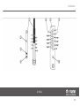
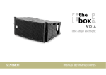
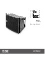
A 10 LA
line array element
user manual
Musikhaus Thomann e.K.
Treppendorf 30
96138 Burgebrach
Germany
Telephone: +49 (0) 9546 9223-0
E-mail: [email protected]
Internet: www.thomann.de
13.11.2013
Table of contents
Table of contents
1
General notes............................................................................................................................................... 4
2
Safety instructions..................................................................................................................................... 7
3
Features....................................................................................................................................................... 11
4
Installation.................................................................................................................................................. 12
4.1 Mounting............................................................................................................................................ 14
5
Connections and operating elements........................................................................................... 21
6
Starting up ................................................................................................................................................. 27
7
Networking and remote control ..................................................................................................... 28
8
Technical specifications....................................................................................................................... 32
9
Plug and connection assignment.................................................................................................... 34
10
Protecting the environment.............................................................................................................. 36
A 10 LA
3
General notes
1
General notes
This user manual contains important information on safe operation of the device. Read and
follow all safety notes and all instructions. Save this manual for future reference. Make sure
that it is available to all persons using this device. If you sell the device to other users, be sure
that they also receive this manual.
Our products are subject to a process of continuous development. We therefore reserve the
right to make changes without notice.
line array element
4
General notes
Symbols and signal words
This section provides an overview of the symbols and signal words used in this user manual.
Signal word
Meaning
DANGER!
This combination of symbol and signal word
indicates an immediate dangerous situation
that will result in death or serious injury if it is
not avoided.
WARNING!
This combination of symbol and signal word
indicates a possible dangerous situation that
can result in death or serious injury if it is not
avoided.
CAUTION!
This combination of symbol and signal word
indicates a possible dangerous situation that
can result in minor injury if it is not avoided.
NOTICE!
This combination of symbol and signal word
indicates a possible dangerous situation that
can result in material and environmental
damage if it is not avoided.
A 10 LA
5
General notes
Warning signs
Type of danger
Warning – high-voltage.
Warning – suspended load.
Warning – danger zone.
line array element
6
Safety instructions
2
Safety instructions
Intended use
This device is intended to be used in a sound reinforcement system. Use the device only as
described in this user manual. Any other use or use under other operating conditions is consid‐
ered to be improper and may result in personal injury or property damage. No liability will be
assumed for damages resulting from improper use.
This device may be used only by persons with sufficient physical, sensorial, and intellectual
abilities and having corresponding knowledge and experience. Other persons may use this
device only if they are supervised or instructed by a person who is responsible for their safety.
Safety
DANGER!
Danger for children
Ensure that plastic bags, packaging, etc. are disposed of properly and are not
within reach of babies and young children. Choking hazard!
Ensure that children do not detach any small parts (e.g. knobs or the like) from
the unit. They could swallow the pieces and choke!
Never let children unattended use electrical devices.
A 10 LA
7
Safety instructions
DANGER!
Electric shock caused by high voltages inside
Within the device there are areas where high voltages may be present. Never
remove any covers.
There are no user-serviceable parts inside.
DANGER!
Electric shock caused by short-circuit
Always use proper ready-made insulated mains cabling (power cord). Do not
modify the mains cable. Failure to do so could result in electric shock/death or
fire. If in doubt, seek advice from a registered electrician.
line array element
8
Safety instructions
CAUTION!
Possible hearing damage
The device can produce volume levels that may cause temporary or permanent
hearing impairment. Over an extended period of time, even levels that seem to
be uncritical can cause hearing damage.
Decrease the volume level immediately if you experience ringing in your ears or
hearing impairment. If this is not possible, keep a greater distance or use suffi‐
cient ear protectors.
NOTICE!
Risk of fire
Do not cover the device nor any ventilation slots. Do not place the device near
any direct heat source. Keep the device away from naked flames.
A 10 LA
9
Safety instructions
NOTICE!
Operating conditions
This device has been designed for indoor use only. To prevent damage, never
expose the device to any liquid or moisture. Avoid direct sunlight, heavy dirt, and
strong vibrations.
NOTICE!
Power supply
Before connecting the device, ensure that the input voltage (AC outlet) matches
the voltage rating of the device and that the AC outlet is protected by a residual
current circuit breaker. Failure to do so could result in damage to the device and
possibly injure the user.
Unplug the device before electrical storms occur and when it is unused for long
periods of time to reduce the risk of electric shock or fire.
line array element
10
Features
3
Features
Special features of the device:
n Active line array element featuring 2 × 1.4" tweeters with titanium diaphragm and 2 × 10"
woofers with 2.5" aluminum voice coil
n 2 × 1000 W class D amplifier
n XLR in and output
n powerCON in and output
n Frequency response: 75 Hz…18 kHz
n Dispersion angle (H × V): 110° × 10°
n Maximum sound pressure level: 131 dB
n Internal Digital Signal Processor (DSP) with four presets
n Network port for connecting a notebook or PC using exclusively the CanBus converters
(item no.: 326058 the box pro USB2CAN CanBus Converter) and the Pronet software (free
download from www.thomann.de).
n Mounting in flown or stacked line arrays with optionally available accessory
n Birch plywood housing with waterproof paint
A 10 LA
11
Installation
4
Installation
Unpack and carefully check that there is no transportation damage before using the unit. Keep
the equipment packaging. To fully protect the device against vibration, dust and moisture
during transportation or storage use the original packaging or your own packaging material
suitable for transport or storage, respectively.
Establish all connections as long as the unit is switched off. Use the shortest possible highquality cables for all connections.
WARNING!
Risk of injury caused by falling objects
Make sure that the installation complies with the standards and rules that apply
in your country. Always secure the device with a secondary safety attachment,
such as a safety cable or a safety chain.
line array element
12
Installation
CAUTION!
Risk of injury due to heavy weight
Due to the heavy weight of the device, at least two persons are required for trans‐
port and installation.
NOTICE!
Possible property damage by magnetic fields
Loudspeakers produce a static magnetic field. Therefore, maintain an appropriate
distance to devices that can be adversely affected or damaged by an external
magnetic field.
NOTICE!
Use of stands
When mounting the device onto a stand, ensure that the stand is in a safe and
stable position and that the weight of the device does not exceed the maximum
permissible load capacity of the stand.
A 10 LA
13
Installation
4.1 Mounting
Overview
Due to its mechanical structure, the device can either be individually put on the ground or
hung, or arranged to line arrays of variable size. The units can be joined together using the
built-in fasteners without any additional parts. For easy, flexible and secure mounting, the
flying frame (item number 313502) is available as optional accessories. This section shows how
easy the assembly is.
Connecting the devices to each
other
To the left and right of the front panel, a safety pin is attached, allowing you to stably connect
the unit to the one directly above it. There is a foldable vertical latch on the rear panel. This
latch fits into the U-rail of the device mounted below, which has a series of numbered bores.
Attach the latch of the upper unit to the U-rail of the underlying device with a safety pin. By
selecting the hole, you can set the desired angle of inclination. Figure and table show the
mechanical parts on the rear side and its function.
line array element
14
Installation
A 10 LA
15
Installation
1 Vertical latch of the overlying unit (in longitudinal and lateral view).
2 Securing bore in the vertical latch. Use this bore when the vertical latch of the device is not folded down, so for single
installation or for the lowest unit in a system.
3 Bore for angular steps of 1 °.
4 Bore for angular steps of 0.5°.
5 U-rail of the device (side view).
6 Clearance bores for odd-numbered angles.
7 Clearance bores for even-numbered angles.
8 Use this bore of the U-rail when the vertical latch of the device is not folded down, so for single installation or for the
lowest unit in a system.
line array element
16
Installation
Flying frame
1 Bores for locking pin.
2 Thread (M10) for attaching standard screw feet for stack mounting.
3 Clearance bores.
4 Vertical latch, suitable for the U-rail of the devices
5 Numbering of the clearance bores.
6 16 mm shackle, optionally available as accessory (item number 323399).
A 10 LA
17
Installation
Installation of a flown system
1.
Attach the flying frame left and right at the front panel of the top unit.
2.
Secure the flying frame with the locking pins that are attached to the top unit.
line array element
18
Installation
Assembly of a device for posi‐
tioning
3.
Position the vertical latch of the flight frame in the U-rail of the top unit.
4.
Secure the latch in the correct position with a safety pin at the U-rail.
5.
For flying operation, mount a shackle on the flying frame. It must be located directly
above the centre of gravity of the entire system. In the figure, the centre of gravity is
marked by ‘C’, the arrow shows the correct position of the U-shackle for this installation
situation.
The flying frame can also be used as a framework for positioning of a device on the floor. In
this case, turn the unit by 180° upside down and attach it to the flying frame, as described in
chapter Installation of a flown system. Then turn the whole thing around and put the flying
frame with the rubber feet on the ground.
A 10 LA
19
Installation
Mounting multiple devices in a
system
Usually, several units are so installed to a line array, that they are arranged arcuate. The figure
alongside shows an example of how four elements can be combined into a system that stands
on the ground (ground stack). In the figure, the centre of gravity is marked by ‘C’.
In a ground stack, no more than four elements with maximum angulation may be
used.
In flying operation, the shackle must be mounted just above the centre of gravity of the entire
system.
line array element
20
Connections and operating elements
5
Connections and operating elements
Rear panel, left side
A 10 LA
21
Connections and operating elements
1 INPUT
Audio signal input with lockable XLR chassis socket. The socket is electronically perfectly symmetrical wired to ach‐
ieve an optimal signal-to-noise ratio and a sufficient power reserve, including A / D conversion.
2 [GND LIFT] pushbutton
If hum is caused by a ground loop, you can use this switch to disconnect the connection between the earth pin of the
device and the signal ground of the device. Switching only has an effect when using balanced connection cables.
3 LINK
Audio signal output with XLR chassis plug to connect other line array elements or speakers to which the input signal
is passed.
4 [TERMINATE] pushbutton
If the devices of a line arrays are networked together, the last unit must be terminated with the built-in load resist‐
ance. Press the pushbutton [TERMINATE]. The LED above it lights up.
5, 6 NETWORK IN/OUT
RJ45 CAT5 connectors for establishing a network connection to the CanBus Converter (item number 326058), to the
Pronet software and to the line array elements.
line array element
22
Connections and operating elements
7 Preset button
This button has two functions:
n If it's kept pressed while turning the device on, the ID assignment is made. The internal digital signal processor
(DSP) assigns a new ID to the device for the remote control within the Pronet network. Each device must have a
unique ID so that it can be represented in the Pronet network. If you assign a new ID, all devices with already
assigned IDs must be turned on and connected to the Pronet network.
n If the device is already on, pressing the button selects the DSP preset. The selected preset is indicated by the
corresponding LED.
– STANDARD
This setting is suitable for vertically flown line arrays, which consist of four to eight devices, or for the middle
area of a larger flown array. It can also be used for stacked arrays.
– LONG THROW
This setting can be used in arrays with more than six or eight devices and be loaded in the top or the top two
devices in order to achieve a more balanced distribution of sound pressure, especially when these devices
are aimed at distant targets or the upper galleries of a large house.
– DOWN FILL / SINGLE BOX
This setting, which provides a much smoother frequency response can be loaded in the lower (usually one or
two) devices of a large flown array to achieve a pleasant sound for the audience near the stage. This setting is
also very useful if the device is used alone at the front on very large stages.
– USER
A 10 LA
23
Connections and operating elements
This LED lights up when the user setting is loaded. This setting corresponds to the user preset no. 1 of the
DSP. In delivery condition, the user setting is identical to the setting STANDARD. If you want to change it,
you must connect the device to a notebook or PC using the CanBus Converter, edit the parameters using the
Pronet software, and save the setting to user memory preset no. 1.
8 LED SIGN/LIMIT
This LED lights green when an input signal is present.
This LED lights red when the internal output signal is limited (due to excessive input signal level!).
9 LED PROT
This LED lights red when the protection circuit of the amplifier module responds due to an internal error and the
amplifier is therefore muted.
This LED lights red when the internal output signal is limited (due to excessive input signal level!).
10 LED ON
This LED lights green when the unit is turned on and the power supply voltage is present.
line array element
24
Connections and operating elements
Rear panel, right side.
A 10 LA
25
Connections and operating elements
11 POWER OUT
Gray lockable powerCon output socket (NAC3FCB). This output is looped through from the blue input socket MAINS
IN . You can use it to feed the power supply to the blue powerCON input sockets MAINS IN of further units. The
number of devices that can be daisy-chained via the POWER OUT socket depends on the power supply voltage. At
230 V, up to four, at 120 V up to two line array elements can be connected.
12 MAINS IN
Blue lockable powerCon input socket (NAC3FA). To turn the unit on, plug the powerCON power cord or the
powerCon connector cable from another device into this socket and turn the plug clockwise to the position ON. To
turn the unit off, pull the locking lever on the plug backwards and turn the plug counter-clockwise to the position
PUSH OFF.
line array element
26
Starting up
6
Starting up
Switching on
After you have made all the required connections, turn on the audio system.
It is recommended to provide one switch for turning on the entire audio system and to always
leave the powerCon plugs connected to the sockets of the individual elements. With this
simple trick you can extend the life of the powerCon connectors.
DSP preset
Set the desired DSP preset (STANDARD, LONG THROW, DOWN FILL / SINGLE BOX or USER).
A 10 LA
27
Networking and remote control
7
Networking and remote control
Network capability
Using the network ports on the rear panel, the individual devices of the entire audio system
can be networked and controlled remotely with a notebook or PC.
Pronet
The communication protocol used in the Pronet network is CanBus.
USB2CAN
All you need to build such a network is the free Thomann Pronet software offered in the Tho‐
mann Cyberstore for download, the CanBus Converter (item number 326058) available from
Thomann and a notebook or PC. Installation and user's guides are included in the free down‐
load of the software.
line array element
28
Networking and remote control
1 Network ports on the rear panel of the first unit.
2 [TERMINATE] pushbutton must not be pressed.
The LED above it is off.
A 10 LA
29
Networking and remote control
3 Network ports on the rear panel of the last unit.
4 [TERMINATE] pushbutton must be pressed.
The LED above it is on.
Network setup and termination
The individual units must be linearly linked by RJ45 CAT5 cable. Beginning and end of the net‐
work bus must be terminated. The beginning is terminated by the CanBus converter. At the
end, the [TERMINATE] switch must be pressed on the rear panel of the last unit to enable the
built-in terminating resistor for termination. The [TERMINATE] switch on all units between the
CanBus converter and the last device must not be pressed.
ID assignment
Each device of a Pronet network must have a unique identifier or ID. By default, the USB2CAN
converter has the ID 0. Any other device can only have an ID equal or higher than 1. There
must be no devices with the same ID on the network. The ID is assigned automatically when a
device connected to the network is turned on for the first time.
Proceed as follows to assign a unique ID to all devices in the Pronet network:
1.
Turn off all devices.
2.
Connect them with the RJ-45 CAT5 cables in the desired order.
line array element
30
Networking and remote control
3.
Press the [TERMINATE] button on the rear panel of the last unit.
4.
Turn on the first device while keeping its [PRESET] button pressed on the rear panel.
5.
Leave the first device turned on and repeat step 4 for all other devices until the last
device is turned on.
When a new device is to be added, only step 4 must be repeated. Each device keeps its ID,
even if it is turned off, as it is stored in the internal memory of the device. The ID is only deleted
or reassigned by explicit allocation as described above. Find more detailed information and
instructions in the User Manual supplied with the Pronet software.
A 10 LA
31
Technical specifications
8
Technical specifications
Speakers
2 × 1.4" tweeters with titanium diaphragm and 2 × 10" woofers with 2.5" alu‐
minum voice coil
Input
XLR chassis socket (balanced)
Input impedance
20 kΩ
Input sensitivity
+4 dBu / 1.25 V
Output
XLR chassis plug
Frequency response (± 3 dB)
75 Hz…18 kHz
Output power
2 × 1000 W (RMS)
Dispersion angle (V × H)
10° × 110° (–6 dB)
Sound pressure level (in 1 m distance)
131 dB (max.)
Operating supply voltage
AC 220 – 240 V , 50/60 Hz
Power consumption
700 W (nominal)
line array element
32
Technical specifications
1700 W (maximum)
Dimensions (W × H × D)
746 mm × 341 mm × 50 mm
Weight
40.3 kg
A 10 LA
33
Plug and connection assignment
9
Plug and connection assignment
Introduction
This chapter will help you select the right cables and plugs to connect your valuable equip‐
ment in such a way that a perfect sound experience is ensured.
Please note these advices, because especially in ‘Sound & Light’ caution is indicated: Even if a
plug fits into the socket, an incorrect connection may result in a destroyed power amp, a short
circuit or ‘just’ in poor transmission quality!
Balanced and unbalanced trans‐
mission
Unbalanced transmission is mainly used in semi-professional environment and in hifi use.
Instrument cables with two conductors (one core plus shielding) are typical representatives of
the unbalanced transmission. One conductor is ground and shielding while the signal is trans‐
mitted through the core.
Unbalanced transmission is susceptible to electromagnetic interference, especially at low
levels, such as microphone signals and when using long cables.
In a professional environment, therefore, the balanced transmission is preferred, because this
enables an undisturbed transmission of signals over long distances. In addition to the conduc‐
tors ‘Ground’ and ‘Signal’, in a balanced transmission a second core is added. This also transfers
the signal, but phase-shifted by 180°.
line array element
34
Plug and connection assignment
Since the interference affects both cores equally, by subtracting the phase-shifted signals, the
interfering signal is completely neutralized. The result is a pure signal without any noise inter‐
ference.
XLR plug (balanced)
1
Ground, shielding
2
Signal (in phase, +)
3
Signal (out of phase, –)
A 10 LA
35
Protecting the environment
10
Protecting the environment
Disposal of the packaging mate‐
rial
For the transport and protective packaging, environmentally friendly materials have been
chosen that can be supplied to normal recycling.
Ensure that plastic bags, packaging, etc. are properly disposed of.
Do not just dispose of these materials with your normal household waste, but make sure that
they are collected for recycling. Please follow the notes and markings on the packaging.
Disposal of your old device
This product is subject to the European Waste Electrical and Electronic Equipment Directive
(WEEE). Do not dispose with your normal household waste.
Dispose of this device through an approved waste disposal firm or through your local waste
facility. When discarding the device, comply with the rules and regulations that apply in your
country. If in doubt, consult your local waste disposal facility.
line array element
36
Notes
A 10 LA
37
Notes
line array element
38
Musikhaus Thomann e.K. · Treppendorf 30 · 96138 Burgebrach · Germany · www.thomann.de