1
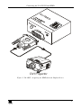
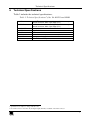
Kramer Electronics, Ltd.
USER MANUAL
Model:
VA-1DVI
Virtual EDID
Contents
Contents
1
2
3
3.1
4
5
5.1
5.2
6
Introduction
Getting Started
Overview
Defining EDID
Your VA-1DVI Virtual EDID
Connecting the VA-1DVI Virtual EDID
Acquiring the EDID
Reading the EDID
Technical Specifications
1
1
2
3
3
4
4
6
7
Figures
Figure 1: VA-1DVI Virtual EDID
Figure 2: VA-1DVI – Acquiring the EDID from the Display Device
Figure 3: Connecting the VA-1DVI Virtual EDID
3
5
6
Tables
Table 1: VA-1DVI Virtual EDID
Table 2: Technical Specifications of the VA-1DVI Virtual EDID
3
7
i
Introduction
1
Introduction
Welcome to Kramer Electronics! Since 1981, Kramer Electronics has been
providing a world of unique, creative, and affordable solutions to the vast
range of problems that confront the video, audio, presentation, and
broadcasting professional on a daily basis. In recent years, we have
redesigned and upgraded most of our line, making the best even better! Our
1,000-plus different models now appear in 11 groups1 that are clearly
defined by function.
Congratulations on purchasing your Kramer Pico TOOLS VA-1DVI Virtual
EDID, which is ideal for:
Presentation graphics distribution
Graphics production studios
Extending a display away from the computer
Each package includes the following items:
VA-1DVI Virtual EDID
This user manual2
2
Getting Started
We recommend that you:
Unpack the equipment carefully and save the original box and
packaging materials for possible future shipment
Review the contents of this user manual
Use Kramer high performance high-resolution cables3
1 GROUP 1: Distribution Amplifiers; GROUP 2: Switchers and Matrix Switchers; GROUP 3: Control Systems; GROUP 4:
Format/Standards Converters; GROUP 5: Range Extenders and Repeaters; GROUP 6: Specialty AV Products; GROUP 7:
Scan Converters and Scalers; GROUP 8: Cables and Connectors; GROUP 9: Room Connectivity; GROUP 10: Accessories
and Rack Adapters; GROUP 11: Sierra Products
2 Download up-to-date Kramer user manuals from our Web site at http://www.kramerelectronics.com
3 The complete list of Kramer cables is on our Web site at http://www.kramerelectronics.com
1
Overview
3
Overview
The Kramer VA-1DVI is a unique DVI EDID emulator, with a DVI-D
input and DVI-D output on DVI-I connectors1. When connecting the
VA-1DVI to a display device and pressing the CAPTURE EDID button, the
VA-1DVI reads and stores the EDID (Extended Display Identification
Data) from the display device2. For example, when the DVI signal is
extended more than 100 meters over fiber optic cable, the VA-1DVI can
emulate the EDID information3. The display can be disconnected and later
reconnected, without rebooting the operating system. In addition, the
VA-1DVI:
Features Max Data Rate - 3.3Gbps
Is housed in a Pico TOOLS enclosure4
Is fed from a 12V power supply
Note that only the digital signal (DVI-D) is available on the DVI connector
To achieve the best performance:
Connect only good quality connection cables, thus avoiding
interference, deterioration in signal quality due to poor matching, and
elevated noise- levels (often associated with low quality cables)
Avoid interference from neighboring electrical appliances and
position your Kramer VA-1DVI away from moisture, excessive
sunlight and dust
Caution – No operator-serviceable parts inside unit.
Warning – Use only the Kramer Electronics input power
wall adapter that is provided with this unit5.
Warning – Disconnect power and unplug unit from wall
before installing or removing device or servicing unit.
1 Note that only the digital signal (DVI-D) is available on the DVI connector
2 The computer needs to have the EDID information available when it boots up, otherwise the DVI output will be disabled
3 The DDC (Digital Display Channel) cable has no effect for distances over 100 meters
4 Four units can be rack mounted side-by-side in a 1U rack space with the optional RK-4PT rack adapter
5 For example, part number 2535-000251
2
KRAMER: SIMPLE CREATIVE TECHNOLOGY
Your VA-1DVI Virtual EDID
3.1 Defining EDID
The Extended Display Identification Data (EDID1) is a data-structure,
provided by a display, to describe its capabilities to a graphics card (that is
connected to the display’s source). The EDID enables the source (for
example, a PC) to “know” what kind of monitor is connected to the output.
The EDID includes the manufacturer’s name, the product type, the timing
data supported by the display, the display size, luminance data and (for
digital displays only) the pixel mapping data.
4
Your VA-1DVI Virtual EDID
Figure 1 and Table 1 define the VA-1DVI Virtual EDID:
Top Side Panel
Top Side Panel
Lower Side Panel
Lower Side Panel
Figure 1: VA-1DVI Virtual EDID
Table 1: VA-1DVI Virtual EDID
#
1
2
3
4
5
Feature
INPUT DVI Connector
12V DC
CAPTURE EDID Button
OUTPUT DVI Connector
POWER LED
Function
Connect to the DVI source
+12V DC connector for powering the unit
Press to acquire EDID
Connect to the DVI acceptor
Lights when the power is connected
1 EDID is defined by a standard published by the Video Electronics Standards Association (VESA)
3
Connecting the VA-1DVI Virtual EDID
5
Connecting the VA-1DVI Virtual EDID
In the example illustrated in Figure 3, a projector is connected to a PC via
an extended optic cable and the VA-1DVI. The PC needs the display’s
EDID information otherwise it will disable the output.
The configuration illustrated in Figure 3 requires two separate stages:
The VA-1DVI needs to read and store the projector’s EDID information
(see section 5.1)
The VA-1DVI is connected between the PC and the remote projector1,
letting the PC read the acquired information (see section 5.2)
5.1 Acquiring the EDID
For the VA-1DVI to acquire the EDID information, as illustrated in Figure
2, do the following:
1. Connect the OUTPUT DVI connector to the input DVI connector of the
display (for example, a projector).
2. Connect the 12V DC power adapter to the power socket and connect the
adapter to the mains electricity2 (not shown in this illustration).
Make sure that the POWER LED lights.
3. Press the CAPTURE EDID button.
The POWER LED turns off while the EDID information is read and stored
in the VA-1DVI non-volatile memory. Once the POWER LED lights
again, the EDID is stored.
4. Disconnect the projector’s DVI connector from the OUTPUT DVI on the
VA-1DVI.
5. Disconnect the power source.
1 Same projector
2 Also make sure that the projector is connected to the power supply
4
KRAMER: SIMPLE CREATIVE TECHNOLOGY
Connecting the VA-1DVI Virtual EDID
DVI Projector
Figure 2: VA-1DVI – Acquiring the EDID from the Display Device
5
Connecting the VA-1DVI Virtual EDID
5.2 Reading the EDID
For the PC to read the EDID information, as illustrated in Figure 3, do the
following1:
1. Connect a DVI source (for example, a DVI computer graphics source) to
the INPUT DVI connector.
2. Connect the OUTPUT DVI connector of the VA-1DVI to the projector.
3. If required2, connect the 12V DC power adapter to the power socket and
connect the adapter to the mains electricity.
Turn the DVI source ON only after connecting the VA-1DVI, so it can acquire
the EDID properly
Figure 3: Connecting the VA-1DVI Virtual EDID
1 Switch OFF the power on each device before connecting it to your VA-1DVI
2 Usually, the PC can supply power to the unit
6
KRAMER: SIMPLE CREATIVE TECHNOLOGY
Technical Specifications
6
Technical Specifications
Table 2 includes the technical specifications:
1
Table 2: Technical Specifications of the VA-1DVI Virtual EDID
INPUT:
OUTPUT:
BANDWIDTH:
CONTROLS:
POWER SOURCE:
DIMENSIONS:
WEIGHT:
OPTIONS:
2
1 x DVI Dual Link, DVI 1.0, 1.2Vpp on a DVI Molex 24-pin
female connector; DDC signal 5Vpp (TTL)
2
1 x DVI , Dual Link, DVI 1.0, 1.2Vpp on a DVI Molex 24-pin
female connector; DDC signal 5Vpp (TTL)
3.3Gbps
Capture EDID button
12V DC, 40mA
6cm x 6.5cm x 3cm (2.36" x 2.56" x 1.18") W, D, H
0.15 kg. (0.55 lbs) approx.
RK-4PT 19" rack adapter
1 Specifications are subject to change without notice
2 On a DVI connector. Note that only the digital signal (DVI-D) is available on the DVI connector
7
8
KRAMER: SIMPLE CREATIVE TECHNOLOGY
For the latest information on our products and a list of Kramer
distributors, visit our Web site: www.kramerelectronics.com,
where updates to this user manual may be found.
We welcome your questions, comments and feedback.
Safety Warning:
Disconnect the unit from the power supply before
opening/servicing.
Caution
Kramer Electronics, Ltd.
Web site: www.kramerelectronics.com
E-mail: [email protected]
P/N: 2900-000119 REV 2