1
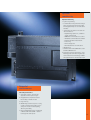
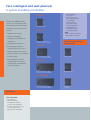
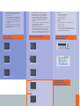
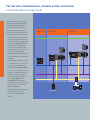
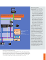
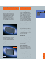
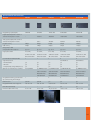
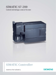
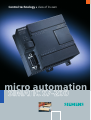
Control technology a class of its own
micro automation
SIMATIC S7-200
Communicative, modular, compact:
So small – and so powerful
The Micro PLC SIMATIC S7-200 is truly
SIMATIC S7-200 delivers consistently
in a class of its own: it’s both compact
economical solutions. The entire
and highly powerful – especially in
system family features
relation to its real-time response – it’s
• Powerful performance,
fast, features great communications
• Optimum modularity and
options and comes with really easy-
• Open communications.
to-operate software and hardware.
In addition, the SIMATIC S7-200 makes
But there’s more to it than that: the
your job even easier: the Micro PLC is
Micro PLC SIMATIC S7-200 has a con-
really easy to program. It enables fast
sistently modular design – for cus-
and easy realization of applications –
tomized solutions which aren’t too
and the new toolbox concept for the
large for the present but open-ended
software accelerates and facilitates
enough to be expanded anytime in
your work even more.
the future.
This Micro PLC is now in successful
All this makes the SIMATIC S7-200 a
use in millions of applications around
real economic alternative in open-
the world – in both stand-alone solu-
loop control for the lower perfor-
tions and networks.
mance range. For any applications in
Find out for yourself what the SIMATIC
automation engineering that con-
S7-200 has to offer!
stantly depend on innovation and
optimum customer benefit.
Open
communication
Open communication
1. Integrated standard RS-485 interface with
data transmission mode dependent
between 0.3 and 187.5 kbit/s
2. PPI protocol functioning as system bus
for trouble-free networking
3. Programmable mode with user-specific
protocols for any peripheral devices
4. Fast connection to PROFIBUS via module
as a slave
5. Powerful to AS-Interface as a master
6. Communications anywhere thanks to
modem link (for remote maintenance,
teleservice or telecontrol)
7. Connection to Industrial Ethernet via
Ethernet module
8. Now also featuring Internet link via
Internet module
Optimal
modularity
Optimal modularity
1. Systems engineering:
• 5 distinct CPUs in the performance range
with comprehensive basic functionality
and integrated Freeport communications
interface
• A wide range of expansion modules for
various functions:
– Digital/analog expansions, scalable to
specific requirements
– PROFIBUS communications as a slave
– AS-Interface communications as a master
– Exact temperature measurement
– Positioning
– Remote diagnostics
– Ethernet/Internet communications
• HMI functions
• Software STEP 7-Micro/WIN with toolbox
and Micro/WIN add-ons
2. Compelling systems engineering – now
featuring precise dimensioning and optimum solutions for a wide range of different requirements for one automation task
Powerful
performance
Powerful performance
1. Small and compact – ideal for any
applications where space is tight
2. Integrated and comprehensive basic
functionality in all CPU models
3. Large memory
4. Outstanding real-time response – being
in total command of the entire process
at any time means increased quality,
efficiency and safety
5. Easy to handle thanks to the user-friendly
software STEP 7-Micro/WIN – ideal for
both beginners and experts
I3I
Fast, intelligent and well-planned:
A system of endless possibilities
CPU 221
• Expansion modules
can be scaled according
to requirements
The Micro PLC SIMATIC S7-200
• Digital expansion
modules from 4/4 to
16/16 inputs/outputs
comes in one of five distinct CPUs
with different performance ranges.
6/4 inputs/outputs
That makes customizing solutions
a breeze:
• Modular buildingblock system
CPU 222
• Analog expansion
modules from 4/0, 4/1
to 0/2 inputs/outputs
NEW:
Power modules for switching
loads: 5-A-DC or 10-A relay
• High basic functionality
• Modular expandability
• Integrated, programmable PPI
interface(s)
• Excellent real-time response
• Extremely fast and precise
8/6 inputs/outputs (I/O)
+ max. 2 modules = 78 I/Os
Digital and analog
expansions
CPU 224
sequence and process control
• Gapless control of time-critical
processes based on time interrupts
• Compact design
14/10 inputs/outputs (I/O)
+ max. 7 modules = 168 I/Os
Input modules
• Easy and handy connection
method based on removable
CPU 226
terminal strips on the CPU and
expansion modules
24/16 inputs/outputs (I/O)
+ max. 7 modules = 248 I/Os
Output modules
CPU 226 XM
24/16 inputs/outputs (I/O)
+ max. 7 modules = 248 I/Os
Software
STEP 7-Micro/WIN
• Easy handling
• Windows standard
• Configuration instead of
programming: the Wizards
• Enormous instruction set easy
to use by drag-and-drop
• Status for STL, LAD and CSF
Input/output
modules
• Modules for exact temperature
measurement to a tenth of a
degree Celsius:
• Integrated PPI interface as S7-200
system bus or as freely programmable interface – for connecting
printers, barcode scanners etc.
• From CPU 222 upwards PROFIBUScapable via PROFIBUS DP slave
module
• From CPU 222 upwards functionality
as AS-Interface master via
AS-Interface module
• EM 241 modem module with integrated complete functions for PLC communications such as remote maintenance, telecontrol, remote diagnostics,
reporting, remote data transmission
– RTD module for measurement
of resistance temperature
– TC module for measuring via
thermocouples of common
models
• EM 253 positioning module for
controlling stepper motors and
servodrives
TP 070
• Low-cost touch panel
• Numeric fields
• Bars and buttons
• Clear contrast
TD 200
• User-friendly, 2-line text display
• 187.5 kbit/s
• Clear contrast
• Connection possibility for other
operator panel and touch panels of
the SIMATIC HMI family
Specific
expansions
Communication
Operating and
monitoring
RTD temperature
measurement
AS-Interface master
max. 2 modules
TD 200
TC temperature
measurement
PROFIBUS DP slave
max. 2 modules
TP 070
Positioning module
EM 253
Modem module
EM 241
NEW
Connection
possibilities of all
SIMATIC panels
Ethernet module
CP 243-1
NEW
I5I
IT module
CP 243-1 IT
For service, maintenance, remote action and more:
Communication at every level
The communications possibilities of
the Micro PLC SIMATIC S7-200 are
unique. The integrated standard
RS-485 interfaces can operate at
data transmission rates from 0.3 to
187.5 kbit/s functioning as follows:
CPU 221
CPU 222
CPU 224
• As a system bus with a maximum
of 126 stations. In this capacity, for
example, it is possible to network
programming devices, SIMATIC HMI
products and SIMATIC CPUs without
a problem. The integrated PPI
protocol is used for pure S7-200
networks. In a network consisting
of TIA components (SIMATIC
S7-300/400 and SIMATIC HMI etc.),
…
the S7-200 CPUs are integrated as
MPI slaves.
…
• In programmable mode (up to max.
115.2 kBaud) with user-specific
protocols (e.g. ASCII protocol).
That means the SIMATIC S7-200 is
open for any connected device; for
example, it enables connection of
a modem, barcode scanner, PC,
non-Siemens PLC and much more.
Up to 31 MICROMASTER- or
MIDIMASTER-model frequency
converters can be controlled via the
USS protocol for drives without
additional hardware.
• The Modbus RTU Library included
in the package also enables
connection to a Modbus RTU
network.
MICROMASTER
Sensors Actuators
Modem communications
The S7-200 CPUs can be accessed nearly
anywhere in the world by modem via wired
network or radio.
CPU 226/CPU 226 XM
Expansion modules
• Teleservice: the modem communication
option is useful for avoiding expensive
service calls. Two modems are all you need
for remote use of the complete range of
functions such as program transfer, status
or control; the communications tools are
integrated as a standard feature. External
PCMCIA modems can be used as local
modems.
• Telecontrol: you can call up messages and
measured values via modem as well as
define new setpoints or commands. In this
case, one head-end can control a nearly
unlimited number of tributary stations.
The protocols for data transmission are
freely selectable, e.g. for sending SMS
messages directly to a cell phone or fault
message to a fax machine. Preparations
are being made to handle other protocols.
Industrial Ethernet/
Internet
Speedy PROFIBUS connection
…
DI/DO/AI/AO
PPI / MPI
Slave
Freeport
• Programming device/PC
• Text display
• Operator panel
• Printer
• Modem
• Barcode reader
• Devices from other vendors
All 222-series CPUs or later can be run via
the EM 277 communications module as a
norm slave on the PROFIBUS DP with a
transmission rate of up to 12 Mbit/s. This
open feature of the S7-200 to higher-level
PROFIBUS DP control levels ensures you can
integrate individual machines into your
production line. With the EM 277 expansion
module, you can implement PROFIBUS
capability of individual machines equipped
with S7-200.
Powerful AS-Interface connection
PROCESS FIELD BUS
S7-300/400
LOGO!
The CP 243-2 turns series-222 CPUs or later
into powerful masters on the AS-Interface.
According to the new AS-Interface
specification V 2.1, you can connect up to
62 stations, making even analog sensors
easy to integrate. In accordance with the
new AS-Interface specification, you can also
connect up to 248 DIs + 186 DOs in the
maximum configuration. The max. number
of 62 stations can include up to 31 analog
modules. The configuration of the slaves
and reading/writing of data is supported by
the handy AS-Interface Wizard.
Fast access via the Internet and Ethernet
Fast configuration, programming and monitoring via Ethernet from a central location can save time
and money. For example, the Internet module CP 243-1 IT was designed to provide an easy universal
PLC link via FTP to various computers for access via the Internet. Or take the Ethernet module CP 243-1
which can be used to quickly access S7-200 process data via Ethernet for archiving or further processing.
STEP 7-Micro/WIN configuration support in this environment guarantees easy commissioning and
convenient diagnostics. OPC makes open data exchange with PC applications possible.
I7I
So easy to use:
The software for plug & play
Extremely easy to operate ...
• PID controllers,
The programming software STEP 7-
• Mathematical calculations,
Micro/WIN features especially time-
• Table operations and
saving and powerful tools – and that
• Communications routines, like the
means great cost savings in your day-
one for Freeport operation, only
to-day work. Operation of the pro-
need to be programmed once and
gramming software is the same as
can then be used over and over
in standard Windows applications.
again.
Functions are selected by way of
Wizards within Micro/WIN enable easy
mouse-click, a button bar or simply
configuration instead of program-
by drag & drop.
ming. Following the menu-based
There is an extensive SIMATIC com-
system, you enter a few parameters
mand set available, which can also be
and the software generates the
programmed in accordance with
executable program.
IEC 1131 upon request. On-line help
... even for commissioning,
offers optimum context-related sup-
servicing and diagnostics
port. STEP 7-Micro/WIN lets you dis-
The integrated on-line functions such
play and program various projects on
as program and table status as well
the monitor at the same time – and
as runtime edit or the programming
copy entire sections of a program
and system monitoring option via
from one program to another at the
modem from anywhere in the world
click of your mouse.
make STEP 7-Micro/WIN a unique tool.
Thanks to structured programming
For this, STEP 7-Micro/WIN features
and the library concept with its own
integrated modem support for
symbol and variable tables, you can
modems with Windows drivers.
design your program clearly and optimize the use of memory. This program
structure also ensures that program
sections such as
SIMATIC Microcomputing
• Controls data exchange between CPU-PC
via standard Microsoft mechanisms such
as OLE, OPC …
• Data exchange between CPU and applications such as Visual Basic, Visual C++,
Excel, Designer, Delphi, Photoshop etc.
• Collection of controls, displays and
mechanisms allows easy generation of a
user interface on your PC
The Toolbox TP Designer features:
• A graphical configuration tool for the
TP 070 touch panel
• Extremely easy configuration of complex
visualization tasks
The Toolbox Command Library features:
• The USS protocol library containing all
programming blocks required for
controlling drives with the USS bus
• The Modbus library containing all the
commands necessary for communicating
in the Modbus
The Wizards at a glance
• TD 200
• PID controllers
• Fast counters
• NetRead – NetWrite
• AS-Interface Wizard
• Ethernet Wizard
• Internet Wizard
• Modem Wizard
• Positioning Wizard
• Control Panel
• Configuration instead of programming
I9I
Expandable, flexible and powerful:
Extras to meet any needs
TOP in real-time
response
The advanced technology down to
Time interrupts
Alarm inputs
the last detail ensures our new CPUs
• Between 1 and 255 ms, with a
• 4 independent inputs
deliver excellent real-time response
rates:
• 4 and/or 6 independent hardware
resolution of 1 ms
• For registering signals in rapid
• For example: it is possible to record
and process signals during fast-
counters with 30 kHz each, e.g. for
action insertion of screws at an RPM
fast 4-edge internal evaluation for
rate of 3000 1/min after just a
exact position monitoring with
quarter turn. This enables very
incremental position encoder or for
precise recording, for instance, of
extremely fast counting of process
tightening torques (M) to ensure
events
optimum fastening of the screw.
– for maximum process safety
• Pulse capturing function for signals
> 0.2 ms for fast events from the
application
• 2 pulse outputs, each 20 kHz with
pulse-time modulation as well as
definition of pulse separation – e.g.
for controlling stepper motors
• 2 time interrupts starting at 1 ms
and adjustable in increments of
1 ms – for gapless control of rapidly
changing processes
• Response time of 200 µs–500 µs
for signal detection/300 µs for signal
output
• Response to positive-going and/or
negative-going signal edge
• Max. 16 interrupts in one queue
depending on prioritization
• 4 independent alarm inputs, input
filter time 0.2 ms to program action
succession
Fast counters
• Operating independently of each
other, of other operations and of
4/6 independent
hardware counters
Schematic representation of a process
with real-time requirements
4 independent
interrupt inputs
4 Transfer
4 Transfer
the program cycle
2 x 20-kHz
pulse outputs
3 Processing
• Interrupt triggering when user-
3 Processing
2 Testing
selectable counted values are
reached – reaction time from the
Fast
analog inputs
1 Drive
Analog
potentiometer
detection of an input signal to
switching of an output is 300 µs
Time interrupt
2 Testing
Process
intervals
1 Drive
Real-time clock
Simultaneous
execution of all
working steps
Fast command
execution
Time response of real-time requirement (t)
• 4-edge evaluation when incremen-
Short cycle times
tal position encoders are used for
exact positioning
• Fast analog inputs – signal
conversion with 25 µs, 12-bit
resolution
• Real-time clock
Feature
CPU 221
CPU 222
CPU 224
CPU 226
Independent hardware counters
4
4
6
6
Independent alarm inputs
4
4
4
4
Pulse outputs
2
2
2
2
Time interrupts
1 to 250 ms
1 to 250 ms
1 to 250 ms
1 to 250 ms
Real-time clock
optional
optional
integrated
integrated
Binary processing speed
0.37 µs
0.37 µs
0.37 µs
0.37 µs
Great well-rounded technology
Small and practical
SITOP power – fits right in with
EEPROM memory modules
the SIMATIC S7-200
A small optional EEPROM memory
SITOP power 24/3.5 A is the optimum
module can save you a lot of time and
backup power supply in the event the
costs. It makes it very easy to copy,
standard SIMATIC S7-200 CPU can no
update or exchange your user pro-
longer deliver power to connected
gram on the device. And if necessary
consumers. The power supply is de-
you can use this module to send a
signed for, and functions entirely in
program quickly and inexpensively to
tune with, the Micro PLC and can be
your customers. You just shut off the
integrated into the PLC network like
power, plug in the module, turn it all
an S7-200 module.
back on – and the program is instantly
Design of terminal block
updated. The configuration of the
TD 200 can also be updated using
this module.
Battery module
And to make sure no user data gets
lost, you can use the optional battery
module for long-term backups to extend backup time from the roughly
5 days of internal backup to, in general, a total of 200 days.
For tough customers: SIPLUS additions
Real-time clock
Whether you need to count operating
Operating under extreme conditions?
No problem! If you have to operate
hours, warm up rooms or attach a
time stamp to messages: the integrat-
your system in an extended tempera-
ed real-time clock on the S7-200 runs
ture range, require added condensa-
to the minute and to the day via the
tion protection or demand other volt-
software according to your settings –
age ratings, then SIPLUS additions is
even in leap years.
the solution for you. It lets you adapt
your CPUs to your special requirements.
+70 °C
Analog potentiometers
With the integrated analog potentiometers on the S7-200, you can optimize the process sequence almost
“according to feel” without a PC or
visualization. They let you fine-tune
the contents of data registries, time
values, preassigned counter values or
other parameters without meddling
with the program. This is a practical
-25 °C
way, for example, to change a welding
time or delay time quickly and directly.
I 11 I
Facts, Facts, Facts:
System data
Identical technical specifications of the CPUs 221, 222, 224, 226 and 226 XM:
Feature
CPU 221, 222, 224, 226, 226 XM
32-bit floating-point arithmetic in accordance with IEEE norm
yes
Fully configurable, integrated PID controller
yes, up to 8 independent PID controllers
Bit processing speed
0.37 µs
Time-controlled interrupts
2 (cycle time between 1 and 255 ms at 1 ms resolution)
Hardware interrupts (edge detection at inputs)
max. 4 inputs
Flags, timers, counters
256 each
High-speed counters
4–6 (depending on CPU), max. 30 kHz
Pulse outputs (pulse-width or frequency-modulated)
2 outputs, 20 kHz each (for DC versions)
Program and data memory
retentive (retained by power-off)
Storage of dyn. data in the event of a power failure
retentive: via internal high-performance capacitor and/or add.
battery module, retained by power-off: loading of data block
with STEP 7-Micro/WIN or by user program to integrated
EEPROM
– Storage time via high-performance capacitor
typ. 50 –190 h (depending on CPU)
– Storage time via optional battery module
typ. 200 days
Integrated communications interface
yes, RS-485 interface supporting the following
operating modes: PPI master or slave/MPI slave/Freeport
The CPUs
(freely configurable ASCII protocol)
Max. baud rate
187.5 kbaud (PPI/MPI) or 38.4 kbaud (Freeport)
Programming software
STEP 7-Micro/WIN supports all standards such as STL, CSF or LAD
Optional program memory module
yes, configurable in CPU, for program transmission
DC/DC/DC version
yes
Supply voltage
24 V DC
Digital inputs
24 V DC
Digital outputs
24 V DC, max. 0.75 A, parallel connection possible for higher switching capacity
AC/DC/relay version
yes
Supply voltage
85–264 V AC
Digital inputs
24 V DC
Digital outputs
5–30 V DC or 5–250 V AC, max. 2 A (relay)
Specific technical data on the CPUs
Features
CPU 221
CPU 222
CPU 224
CPU 226
CPU 226 XM
Integrated dig. inputs/outputs
6 DI/4 DO
8 DI/6 DO
14 DI/10 DO
24 DI/16 DO
24 DI/16 DO
–
40/38/78
94/82/168
128/120/248
128/120/248
channels with expansion modules
–
8/4/10
28/14/35
28/14/35
28/14/35
Program memory
4 kByte
4 kByte
8 kByte
8 kByte
16 kByte
Data memory
2 kByte
2 kByte
5 kByte
5 kByte
10 kByte
via high-performance capacitor
typ. 50 h
typ. 50 h
typ. 190 h
typ. 190 h
typ. 190 h
High-speed counters
4 x 30 kHz,
4 x 30 kHz,
6 x 30 kHz,
6 x 30 kHz,
6 x 30 kHz,
of which 2 x 20 kHz
of which 2 x 20 kHz
of which 4 x 20 kHz
of which 4 x 20 kHz
of which 4 x 20 kHz
A/B counter usabler
A/B counter usabler
A/B counter usabler
A/B counter usabler
A/B counter usabler
1
1
1
2
2
both interfaces
both interfaces
Digital inputs/outputs/max. number of
channels with expansion modules
Analog inputs/outputs/max. number of
Storage of dyn. data
Communications interfaces RS 485
Supported protocols:
– PPI master/slave
yes
yes
yes
yes
yes
– MPI slave
yes
yes
yes
yes
yes
– Freeport (freely config. ASCII protocol)
yes
yes
yes
yes
yes
Optional communications possibilities
not expandable
yes, PROFIBUS DP Slave
yes, PROFIBUS DP Slave
yes, PROFIBUS DP Slave
yes, PROFIBUS DP Slave
and/or AS-Interface
and/or AS-Interface
and/or AS-Interface
and/or AS-Interface
Master/Ethernet/
Master/Ethernet/
Master/Ethernet/
Master/Ethernet/
Internet/Modem
Internet/Modem
Internet/Modem
Internet/Modem
1
1
2
2
2
Real-time clock
optional
optional
yes
yes
yes
Integrated 24-V-DC sensor supply volt.
max. 180 mA
max. 180 mA
max. 280 mA
max. 400 mA
max. 400 mA
Integrated 8-bit analog potentiometer
(for commissioning, value change)
Removable terminal strip
–
–
yes
yes
yes
Dimensions (W x H x D in mm)
90 x 80 x 62
90 x 80 x 62
120,5 x 80 x 62
196 x 80 x 62
196 x 80 x 62
I 13 I
Facts, Facts, Facts:
System data
Technical data
Digital and analog expansions
Digital I/O modules
EM 221
EM 222
EM 222
Number of inputs/outputs
8 DI (DC)
8 DO (DC)
8 DO (relay)
Number of inputs
8
–
–
Input type
24 V DC
–
–
Sinking/sourcing
x/x
–
–
Input voltage
24 V DC, max. 30 V
–
–
Isolation
yes
–
–
in groups of
4 inputs
–
–
Number of outputs
–
8
8
Output type
–
24 V DC
relay
Output current
–
0.75 A in group-parallel connection
2A
Output voltage DC
–
20.4–28.8 V
5–30 V
(permissible range) AC
–
–
5–250 V
Isolation
–
yes
yes
in groups of
–
4 outputs
4 outputs
Removable terminal strip
yes
yes
yes
Dimensions (W x H x D in mm)
46 x 80 x 62
46 x 80 x 62
46 x 80 x 62
Digital I/O modules
EM 221
Number of inputs/outputs
16 DI (DC)
4 DO (DC)
4 DO (relay)
Number of inputs
16
–
–
Type of input
24 V DC
–
–
Sinking/sourcing
x/x
–
–
Input voltage
24 V DC, max. 30 V
–
–
Isolation
yes
–
–
in groups of
4 inputs
–
–
Number of outputs
–
4
4
Output type
–
24 V DC
relay
Output current
–
5 A max. per output, switchable
10 A max. per output
possible for higher switching capacity
New
EM 222
New
EM 222
New
in parallel for greater power
Output voltage DC (permissible range) AC
–
20.4–28.8 V
12–250 V
Isolation
–
yes
yes
in groups of
–
1 output
1 output
Removable terminal strip
yes
yes
yes
Dimensions (W x H x D in mm)
71.2 x 80 x 62
46 x 80 x 62
46 x 80 x 62
Accessories
PC/PPI cable (Single Master)1
RS 232 Smart Cable (Multimaster 2, 3) USB Smart Cable (Multimaster 4)
Isolation
yes
yes
yes
Power supply
from CPU
from CPU
from USB Port
Supported protocols
PPI and ASCII (Freeport); 10/11 bit
PPI and ASCII (Freeport); 10/11 bit
PPI; 10/11 bit
PPI communication
9.6 k; 19.2 k
9.6 k; 19.2 k; 187.5 k
9.6 k; 19.2 k; 187.5 k
Communication setting
DIP switch
DIP switch; RS 232 automatically
unnecessary
LED display
yes
yes
yes
Required software
STEP 7-Micro/WIN
STEP 7-Micro/WIN V3.2 from SP4
STEP 7-Micro/WIN V3.2 from SP4
1
3
2
PC/PPI cable: the low-cost solution for 1 CPU; RS 232 Smart Cable: for networks and external modems (also GSM);
Settings, e.g. for modems permanently stored; 4 USB Smart Cable: Multimaster for USB
Technical data
Digital I/O modules
EM 223
EM 223
EM 223
EM 223
EM 223
EM 223
Number of inputs/outputs
4 DI (DC) / 4 DO (DC)
4 DI (DC) / 4 DO (relay) 8 DI (DC) & 8 DO (DC)
8 DI (DC) & 8 DO (relay) 16 DI (DC) & 16 DO (DC) 16 DI (DC) & 16 DO (relay)
Number of inputs
4
4
8
8
16
16
Input type
24 V DC
24 V DC
24 V DC
24 V DC
24 V DC
24 V DC
sourcing
x/x
x/x
x/x
x/x
x/x
x/x
Input voltage
24 V DC, max. 30 V
24 V DC, max. 30 V
24 V DC, max. 30 V
24 V DC, max. 30 V
24 V DC, max. 30 V
24 V DC, max. 30 V
Sinking/
Isolation
no
no
yes
yes
yes
yes
in groups of
–
–
4 inputs
4 inputs
8 inputs
8 inputs
Number of outputs
4
4
8
8
16
16
Output type
24 V DC
relay
24 V DC
relay
24 V DC
relay
0.75 A in
2A
0.75 A in group-
2A
0.75 A in group-
2A
Output current
parallel conncection
parallel conncection
parallel conncection
possible for higher
possible for higher
possible for higher
switching capacity
switching capacity
switching capacity
Output voltage DC
20.4–28.8 V
5–30 V
20.4–28.8 V
5–30 V
20.4–28.8 V
20.4–28.8 V
(permissible range) AC
–
5–250 V
–
5–250 V
–
–
Isolation
no
no
yes
yes
yes
yes
in groups of
–
–
4 outputs
4 outputs
4/4/8 outputs
4 outputs
yes
yes
yes
yes
yes
yes
46 x 80 x 62
46 x 80 x 62
71.2 x 80 x 62
71.2 x 80 x 62
137.3 x 80 x 62
137.3 x 80 x 62
Removable
terminal strip
Dimensions
(W x H x D in mm)
Analog I/O modules
EM 231
EM 232
EM 235
Number of inputs/outputs
4 AI
2 AO
4 AI & 1 AO
Number of inputs
4
–
4
Input type
0–10 V/0–20 mA
–
0–10 V/0–20 mA
Voltage ranges
0–10 V, 0–5 V
–
0–10 V, 0–5 V
+/–5 V, +/–2.5 V
Resolution
12 bit
+/–5 V, +/–2.5 V and others
–
12 bit
Isolation
no
–
no
Number of outputs
–
2
1
Output type
–
+/–10 V, 0–20 mA
+/–10 V, 0–20 mA
Resolution
–
12 bit volt.,
12 bit volt.
11 bit current
11 bit current
Isolation
–
no
no
Removable terminal strip
no
no
no
Dimensions (W x H x D in mm)
71.2 x 80 x 62
46 x 80 x 62
71.2 x 80 x 62
I 15 I
Facts, Facts, Facts:
System data
Technical data
Temperature measurement modules
EM 231 TC thermocouples
EM 231 RTD resistance-type sensors
Number of inputs/outputs
4 AI
2 AI
Number of inputs
4
2
Input type
Thermocouples
Pt 100, 200, 500, 1000 ohm,
Type S, T, R, E, N, K, J
Pt 10.000,
Voltage +/–80 mV
Ni 10, 120, 1000 ohm,
Specific expansions
R 150, 300, 600 ohm
Resolution
15 bit + sign
15 bit + sign
Isolation
500 V AC
500 V AC
Cold-junction compensation
yes
not nec.
Wiring
two-wire
two-, three- or four-wire
Max. wire length to sensor
100 m
100 m
Removable terminal strip
no
no
Dimensions (W x H x D in mm)
71.2 x 80 x 62
71.2 x 80 x 62
The program features temperature values in either Celsius or Fahrenheit displayed to the tenth of a degree.
Positioning module EM 253
Number of inputs
5 points (RP, LMT–, LMT+, ZP, STP)
Type of inputs
active high/active low (IEC Type 1 sink, except ZP)
Number of integrated outputs
6 points (4 signals)
Type of outputs
P0+, P0–, P1+, P1–
RS-422 driver
P0, P1+, DIS, CLR
Open drain
Switching frequency
P0+, P0–, P1+, P1–
200 kHz
Power supply:
L + supply voltage
11 to 30 V DC
Logic output voltage
+5 V DC +/–10 %, max. 200 mA
L + supply current VS, 5 V DC load
Load current
12-V-DC input
24-V-DC input
0 mA (no load)
120 mA
70 mA
200 mA (rated load)
300 mA
130 mA
Dimensions (W x H x D)
71.2 x 80 x 62
Weight
0.190 kg
Dissipation
2.2 W
V-DC requirements
+5 V DC
190 mA
+24 V DC
70 mA
Technical data
Communications module
EM 277 PROFIBUS-DP modul
CP 243-2 AS-i master module
Interface
1 communications interface RS 485
AS-Interface
Supported protocols:
– MPI slave
– PROFIBUS-DP slave
AS-Interface
Transmission rate
9,600 baud up to 12 Mbaud
– max. 5 ms cycle time with 31 slaves
adaptive
– max. 10 ms cycle time with 62 slaves
Connectable stations:
– Text display TD 200, V2.0 or later
– Operator panels, touch panels
– PG/PC with MPI interface
(CPU downloads/status via
Micro/WIN possible)
– CPU S7-300/400
– PROFIBUS DP master or slaves
max. 62 AS-Interface slaves
Status displays
CPU error, power, DP error, DX mode
Status displays for slaves, error displays
Station address
adjustable on module (0–99)
not necessary
Galvanic isolation
500 V AC
no
Max. cable length (without repeater)
1200 m (bei 93,75 kBaud)
100 m
Removable terminal strip
no
yes
Dimensions (W x H x D in mm)
71 x 80 x 62
71.2 x 80 x 62
Weight in g
175
210
Dissipation in W
2.5
1.8
EM 241 modem module
Isolation (phone line against Logic and …)
1500 V AC (galvanic)
Cable connector
RJ11 (6 points, 4-wire)
Modem standards
Bell 103, Bell 212, V.21, V.22, V.22 bis, V.23c, V.32, V.32 bis, V.34 (standard)
Safety features
Password, callback
Calling method
Pulse or tone dialing
Messaging protocols
Numerical
(SMS)
TAP (alphanumeric)
UCP commands 1, 30, 51
Industrial standard protocols
Mode RTU, PPI, integrated functions for data exchange
Dimensions (W x H x D)
71.2 x 80 x 62
Weight
0.190 kg
Dissipation
2.1 W
V-DC requirements
+5 V DC
+24 V DC
80 mA
70 mA
Ethernet communications modules
CP 243-1
CP 243-1 IT
Transmission rate
10/100 Mbit/s
10/100 Mbit/s
Interfaces (connection Industrial Ethernet)
RJ45
RJ45
Supply voltage
24 V DC
24 V DC
Power consumption via backplane/via 24 V DC external
55 mA /60 mA
55 mA /60 mA
Dissipation DC 24 V
1.75 W
1.75 W
Dimensions (W x H x D)
71.2 x 80 x 62
71.2 x 80 x 62
Weight
150 g
150 g
Number of operable connections
8 S7 connections + 1 PG connection
8 S7 connections + 1 PG connection
Configuration
with STEP 7-Micro/WIN (V3.2 SP1 or later)
with STEP 7-Micro/WIN (V3.2 SP3 or later)
Number of connections to an E-mail server
–
1
E-mail client
–
32 E-mails with max. 1024 characters
Number of FTP/HTTP connections
–
1 /4
Adjustable access protection
–
8 users
Memory capacity of the file system
–
8 MByte
Communication
Phone connection:
S7/PG communication
IT communications
I 17 I
Facts, Facts, Facts:
System data
Technical data
Technical data
Text Display TD 200
Touch Panel TP 070
Display
LCD-backlit, 2-line,
Display
20 characters/line (ASCII, Cyrillic),
• MTBF display and backlighting
10 characters/line (Chinese),
at 25 °C
STN, CCFL-backlit
50,000 h
5 mm character height
• Resolution (pixels)
320 x 240
Controls
8 freely configurable keys
• Display area
5,7” blue mode
Interfaces
1 PPI (RS 485); to set up a
Keypad
Touch (resistive/analog)
network with max. 126 stations
• Switching cycles, min.
1 million
(S7-200, OP, TP, TBP, PG/PC);
Operating system
Windows CE
transmission rates
User memory
Flash (retentive)
9.6/19.2/187.5 kbit/s
• Size
128 KB
Power supply
24 V DC, 120 mA; power supply
Supply voltage
24 V DC
through S7-200 communications
• Power consumption typ.
200 mA at 24 V
interface possible
Integrated interface
RS 485 (19.2 kBit/s)
Ambient temperature
0 to 60 °C
• Log. connections
1; only point-to-point connection
Degree of protection
IP 65 front
Clock
Real-time clock of CPU can be displayed
Dimensions (W x H x D) in mm
148 x 76 x 27
Ambient conditions
• Operating temperature
Text Display TD 200
The TD 200 enables:
• Displays of message texts
• Adjustment of the control program,
e.g. change setpoint
HMI
• Setting of inputs and outputs, e.g. to
switch the motor on and off
– vertical assembly
0 to +50 °C
– tilted up to 35°
0 to +40 °C
• Humidity
Dimensions of front panel in mm (W x H) 212 x 156
Degree of protection front/back
IP 65/IP 20
Certified for
CE/UL/CSA/FM
Functionality
(typ. approx. 20 process diagrams,
10 graphics, several buttons,
Touch Panel TP 070
fixed texts and 50 variables)
The TP 070 is a professional touch panel specially
designed for the SIMATIC S7-200. It handles HMI
funtions for small machines or plants.
≤ 85 %, non-condensing humidity
permissible
• Images
30 max.
• Variables
yes
• Fields per image
20
• Variables per image
10
• Graphic objects
yes
• Text objects
yes
• Bars charts per image
3
Product
Order No.
CPUs
Product
Order No.
Manuals
CPU 221 DC/DC/DC
(not expandable)
6ES7 211 0AA22 0XB0
S7-200 system manual
6ES7 298 8FA22 8AH0
CPU 221 AC/DC/relay
(not expandable)
6ES7 211 0BA22 0XB0
TD 200 text display, user manual
6ES7 272 0AA20 8AA0
CPU 222 DC/DC/DC
6ES7 212 1AB22 0XB0
TP 070 manual
6AV6 591 1DC01 0AA0
CPU 222 AC/DC/relay
6ES7 212 1BB22 0XB0
CP 243-2 communications processor manual
6GK7 243 2AX00 8AA0
CPU 224 DC/DC/DC
6ES7 214 1AD22 0XB0
HMI
CPU 224 AC/DC/relay
6ES7 214 1BD22 0XB0
TD 200 text display, 2-line with cable (2.5 m)
CPU 226 DC/DC/DC
6ES7 216 2AD22 0XB0
and mounting accessories, 187.5 kbaud
CPU 226 AC/DC/relay
6ES7 216 2BD22 0XB0
TP 070 touch panel, 5.7” screen size,
CPU 226XM DC/DC/DC
6ES7 216 2AF22 0XB0
analog-resistive touch, backlighting
CPU 226XM AC/DC/relay
6ES7 216 2BF22 0XB0
Accessories
6ES7 272 0AA30 0YA0
6AV6 545 0AA15 2AX0
Expansion modules
Battery module
6ES7 291 8BA20 0XA0
Digital and analog expansions
Memory module EEPROM
6ES7 291 8GE20 0XA0
Input module 8 x DI 24 V DC
6ES7 221 1BF22 0XA0
Clock module, incl. battery (221,222)
6ES7 297 1AA20 0XA0
Input module 8 x DI 120 / 230 V
6ES7 221 1EF22 0XA0
Extension cable for expansion modules, 0.8 m
6ES7 290 6AA20 0XA0
Input module 16 x DI 24 V DC
6ES7 221 1BH22 0XA0
PC/PPI cable, RS232/485 cable for PC/Laptop/Modem/
Output module 8 x DO 24 V DC
6ES7 222 1BF22 0XA0
xxx to S7-200, max. 38.4 kbit/s, single master
Output module 8 x DO relay
6ES7 222 1HF22 0XA0
PC/PPI cable, RS232/485 cable for PC/Laptop/Modem/
Output module 8 x DO 120 / 230 V
6ES7 222 1EF22 0XA0
xxx to S7-200, max. 187.5 kbit/s, multimaster
Output module 4 x DO 24 V DC 5 A
6ES7 222 1BD22 0XA0
PC/PPI cable, USB/485 cable for PC/Laptop to S7-200,
Output module 4 x DO relay 10 A
6ES7 222 1HD22 0XA0
max. 187.5 kbit/s, multimaster
6ES7 901 3DB30 0XA0
Input/output module 4 x DI 24 V DC / 4 x DO 24 V DC
6ES7 223 1BF22 0XA0
MPI cable
6ES7 901 0BF00 0AA0
Input/output module 4 x DI 24 V DC / 4 x DO relay
6ES7 223 1HF22 0XA0
CP5511: PCMCIA, Type II, RS485 (PPI/MPI/PROFIBUS)
Input/output module 8 x DI 24 V DC / 8 x DO 24 V DC
6ES7 223 1BH22 0XA0
for PC/Laptop with max. 12 Mbit/s
Input/output module 8 x DI 24 V DC / 8 x DO relay
6ES7 223 1PH22 0XA0
CP5611: PCI card, RS485 (PPI/MPI/PROFIBUS) for
6ES7 901 3BF30 0XA0
6ES7 901 3CB30 0XA0
6GK1 551 1AA00
Input/output module 16 x DI 24 V DC / 16 x DO 24 V DC 6ES7 223 1BL22 0XA0
PC/Laptop with max. 12 Mbit/s
6GK1 561 1AA00
Input/output module 16 x DI 24 V DC / 16 x DO relay
6ES7 223 1PL22 0XA0
Power supply, SITOP power 24 V / 3.5 A
6EP1 332 1SH31
Analog input module 4 AI 12 bit
6ES7 231 0HC22 0XA0
Software
Analog input/output module 4 AI / 1 AO 12 bit
6ES7 235 0KD22 0XA0
Programming software STEP 7-Micro/WIN, V 3.2, 32 bit,
Analog output module 2 AO 12 bit
6ES7 232 0HB22 0XA0
for Win 95/98/Me, NT 4.x, 2000,
Specific expansions
5 languages, incl. documentation on CD; single license
Analog input module RTD, 2 AI, PT100/200/500/1000,
Programming software STEP 7-Micro/WIN, V 3.2, 32 bit,
Ni100/120/1000, Cu10, Wdst. 150/300/600 ohm, 16 bit 6ES7 231 7PB22 0XA0
for Win 95/98/Me, NT 4.x, 2000,
Analog input module TC, 4 AI, ± 80 mV and
5 languages, incl. documentation on CD;
Thermocouples, Type J, K, S, T, R, E, N, 16 bit
6ES7 231 7PD22 0XA0
upgrade from Micro/DOS and Micro/WIN Vx.x to V 3.2
Positioning EM, Positioning expansion module1),
STEP 7-Micro/WIN Add-on: command library V 1.1,
200 kHz, for driving stepper motors or
control of drives (USS protocol) and
servodrives, open-loop control, parameterization
using Micro/WIN
for STEP 7-Micro/WIN V 3.2
6ES7 277 0AA22 0XA0
configuring of S7-200 Touch Panels, V 1.0
AS-Interface Master Module CP 243-2
6GK7 243 2AX01 0XA0
S7-200 Microcomputing limited, ActiveX components
Modem-EM 1), Modem expansion module for analog
for data access to 1 S7-200, Win 95/98/Me, 2000, NT
telephone networks for remote maintenance, signalling,
S7-200 Microcomputing unlimited,
6ES7 241 1AA22 0XA0
Industrial Ethernet CP 243-1, connection S7-200 to
6GK7 243 1EX00 0XE0
6ES7 850 2BC00 0YX0
6ES7 810 2ML00 0YX0
ActiveX components for data access to S7-200
Network, Win 95/98/Me, 2000, NT
Industrial Ethernet CP 243-1-IT, function as CP 243-1,
in addition: FTP, E-mail, HTML
6ES7 830 2BC00 0YX0
S7-200 Toolbox: TP-Designer for TP 070,
PROFIBUS DP Module EM 277 1)
Industrial Ethernet
6ES7 810 2BC02 0YX3
data transmission via Modbus protocol,
6ES7 253 1AA22 0XA0
Communication
CPU-to-CPU, CPU-to-PC communication
6ES7 810 2BC02 0YX0
6ES7 810 2MU00 0YX0
S7-200 OPC Server for random OPC Clients for
data access to 1 S7-200, Win 95/98/Me, 2000, NT
6ES7 810 2MS00 0YX0
6GK7 243 1GX00 0XE0
1) only for CPUs version 6ES7 xxx xxx21 xxxx and higher
I 19 I
Want more info on the SIMATIC S7-200?
More info on the SIMATIC S7-200 is available anywhere from a Siemens office in
your area, selected electric wholesalers and in the direct mail-order catalog.
More information about SIMATIC S7-200
Name
Internet: www.ad.siemens.de/s7-200
• List of commands (quick reference card)
Company
• Demo software
• Free software updates
Street/No.
• Download of user manuals
P.O. Box
Infoservice – by mail or fax:
Siemens AG, Infoservice, AD/Z 461,
Postal code/City
P.O. Box 23 48, D-90713 Fürth, Germany
Fax: +49 (0) 911/9 78-33 21
Request more info:
“GO! Special Edition“ is our customer newsletter for clever switching and controlling
Micro Automation Sets
CD Software & Solutions
or find more about supplementary technology:
LOGO! modular – nothing could be easier
“The new generation of SITOP power“ – the controlled power supply for SIMATIC S7-200
“SIPLUS additions“ – for operating devices under extreme conditions
Siemens AG
Automation and Drives
Industrie-Automatisierungssysteme
P.O. Box 48 48, D-90327 Nuremberg
ww w. si e m e n s. d e/ s 7 - 2 0 0
Subject to change without prior notice 04/03 | Order No. E20001-A1020-P272-X-7600 | DISPO 06313 | 21C7908 S2S2.52.3.08 WS 040310.0 | Printed in Germany
• Tips & tricks
Department