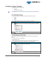
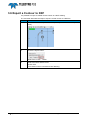
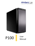
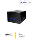
1
Vessel Contour Editor Teledyne PDS Version 1.0.1 July 2015 Teledyne RESON B.V. Stuttgartstraat 42- 44 3047 AS Rotterdam The Netherlands Tel.: +31 (0)10 245 15 00 www.teledyne-reson.com Amendment Record Sheet Rev. Date Reason for Modifications 1.0.1 09/07/2015 Version after review RDG. 1.0.0 07/07/2015 First version of the Manual. Contents 1 Introduction 1.1 1 Vessel Contour Editor ...................................................................................... 1 2 Vessel Contour Editor 3 2.1 2.2 2.3 2.4 General ............................................................................................................ 3 Main Window ................................................................................................... 5 Selection Pane View ........................................................................................ 6 Vessel Contour Shape View(s) ....................................................................... 9 2.4.1 General ...................................................................................................... 9 2.4.2 Active Shape View ..................................................................................... 9 2.4.3 Shape View Toolbar ................................................................................ 10 2.4.4 Context Menu........................................................................................... 11 2.4.5 Grippers ................................................................................................... 12 2.5 Numeric View ................................................................................................ 14 2.5.1 Vessel Contour Points ............................................................................. 14 2.5.2 Device Overview ...................................................................................... 15 3 Operate 17 3.1 3.2 3.3 General .......................................................................................................... 17 Import a DXF drawing.................................................................................... 17 Drawing a Contour ......................................................................................... 19 3.3.1 General .................................................................................................... 19 3.3.2 Using a JPG picture as background ........................................................ 21 3.4 Edit a Contour ................................................................................................ 23 3.4.1 Numerical Editing ..................................................................................... 23 3.4.2 Graphical Editing ..................................................................................... 25 3.4.2.1 Move a point by a gripper ............................................................... 25 3.4.2.2 Shift a Vessel contour..................................................................... 26 3.4.2.3 Rotate a Vessel Contour ................................................................ 26 3.5 Scale a Vessel Contour ................................................................................. 27 3.5.1 Absolute Scaling ...................................................................................... 27 3.5.2 Scaling by Scale Factor ........................................................................... 27 3.6 Export a Contour to DXF ............................................................................... 28 Teledyne PDS - Vessel Contour Editor Contents i Figures Figure 2-1 Figure 2-2 Figure 2-3 Figure 2-4 Figure 2-5 Figure 2-6 Figure 2-7 Figure 2-8 Figure 2-9 Figure 2-10 Figure 2-11 Figure 2-12 Figure 2-13 Figure 2-14 Figure 2-15 Figure 2-16 Figure 2-17 Custom shape ......................................................................................................................3 Overview ..............................................................................................................................4 PDS Explorer .......................................................................................................................4 Main window vessel contour editor ......................................................................................5 Menu bar ..............................................................................................................................5 Selection pane .....................................................................................................................6 Shape views .........................................................................................................................9 Active shape view ............................................................................................................. 10 Toolbar .............................................................................................................................. 10 Context menu view (left) and point (right) ......................................................................... 11 Grippers ............................................................................................................................ 12 Red Gripper ....................................................................................................................... 12 Numeric view – Contour Points......................................................................................... 14 Point selection ................................................................................................................... 14 Edit a field ......................................................................................................................... 14 Numeric view – Device overview ...................................................................................... 15 Device offsets.................................................................................................................... 15 ii Figures Teledyne PDS - Vessel Contour Editor 1 Introduction 1.1 Vessel Contour Editor This manual describes the new vessel contour editor added from of PDS version 4.x.x.x. The vessel contour editor consists of: a selection pane for vessel contour file selection, and other functions, three contour shape views to visualize the contour shapes, and a numerics pane view to display the numerical values of the selected vessel contour shape view. This manual consists of two more chapters: Vessel Contour Editor; describes the views and the functions of the vessel contour editor views. Operate; describes how to use the vessel contour editor. This manual will only explain parts related to the Vessel contour Editor. For other information about Teledyne PDS see the Teledyne PDS User Manual (the file Teledyne PDS User Manual.pdf in the folder ‘manuals’) Teledyne PDS. All Teledyne PDS related manuals are available from the Teledyne PDS Control Center Help menu ‘Help>Open Manuals folder’. This manual is also available as a HTML Help file and can be opened with F1 or with Help > Help Topics from the menu bar. Teledyne PDS Instruction movies are available on the Teledyne PDS YouTube channel. Watch Teledyne PDS instruction movies. Teledyne PDS - Vessel Contour Editor Introduction 1 2 Vessel Contour Editor 2.1 General It is possible to start the vessel contour editor from: The vessel configuration – Custom shape button. Select from the Vessel Configuration – Geometry tab, Custom shape and as 2D shape type: Vessel contours. Figure 2-1 Custom shape The vessel configuration - Overview button. Press the overview button. The vessel contour editor opens with the device offsets listed in the numeric view and the offsets displayed in the vessel Teledyne PDS - Vessel Contour Editor Vessel Contour Editor 3 contour shape view(s). See Device Overview on page 15. Figure 2-2 Overview The PDS Explorer – Projects Common – Vessel contours folder. Expand the Vessel Contours node and select an existing vessel contour, or right click at the vessel contour folder for a context menu and select New File. Figure 2-3 PDS Explorer The vessel contour editor is an application. This means it is possible to run it simultaneously with other PDS modules. The units used in the vessel contour editor are the system units defined in the used coordinate system. The vessel contour editor opens with the main window. 4 Vessel Contour Editor Teledyne PDS - Vessel Contour Editor 2.2 Main Window Figure 2-4 Main window vessel contour editor The vessel contour editor has the following menu bar. Figure 2-5 Menu bar The next table lists the functions of the menu bar. Menu File Help Teledyne PDS - Vessel Contour Editor Function Save Save the vessel contour file with a name of the opened vessel contour file name. Save As… Save the vessel contour file with an entered file name. Exit Exit the vessel contour editor. Version number vessel contour editor Vessel Contour Editor 5 The main window of the vessel contour editor includes: Selection pane view Three vessel contour shape views Numerics bottom pane view 2.3 Selection Pane View Figure 2-6 Selection pane From the selection pane view it is possible to: Select a vessel contour file Generate a new, import or export a vessel contour Select a vessel image Enable or disable shape views Enable or disable a device overview Resize a vessel contour Create a contour from a right / left or back / front contour 6 Vessel Contour Editor Teledyne PDS - Vessel Contour Editor The next table describes the functions of the selection pane. Function Vessel contour file New, Import and Export Vessel image Description From the drop down list it is possible to select a vessel contour file. The file must be available in the PDS project. Press the New button to generate a new vessel contour. Press the Import button to import a DXF drawing. The vessel contour points will be extracted from the DXF file and mapped onto the corresponding vessel contour sides ( Top(x,y) right/Left(y,z) back/Front(x,z). Explode blocks of the DXF drawing prior to import it to PDS. Press the export button to export the vessel contour to a DXF file. The vessel contour of the active pane view is exported. Select from the drown list a vessel photo image. The photo image must be available in or copied to the PDS Explorer – Multimedia folder. The image is displayed in the background of the current selected pane view. The image can serve as a template for easily drawing of the vessel contour. Pane view With the pane view buttons it is possible to show or hide the top view, the right/left or the back/front views. This buttons have a round robin mechanism, this means a button may pressed repeatedly to have another view hide or displayed again. For example with a button it is possible to show the right view, to show the left view and to hide the pane view. Show device overview Teledyne PDS - Vessel Contour Editor Select this option to visualize the position (offsets) of the devices in the vessel contour shape views and have the device offsets listed in the numeric view. (See page 15.) The offsets of the devices are defined in the vessel configuration geometry page. Select from the drop down list the vessel configuration containing the device offsets. Only vessel configurations which are defined in the project are listed. Vessel Contour Editor 7 Function Resize Description It is possible to resize the vessel contour: Absolutely Select the absolute size radio button. The contour will be sized to the entered length, width and height (meters). By scale factor Select the scale factor radio button. The X,Y and Z dimension of the contour will be sized relative by the entered scale factor for the X, Y and / or Z. Press the Resize with the new values. button to resize the contour All view shapes (top, left, right, back and forward) are resized. Press the Recalculate button to recalculate the absolute sizes when the contour was edited. Right/Left contour With this function it is possible to create a mirror image of a contour. A left contour from a right contour, or a right contour from a left contour. Select the associated radio button and press the create button to create the contour. Back/Front contour With this function it is possible to create a mirror image of a contour. A front contour from a back contour, or a back contour from a front contour. Select the associated radio button and press the create button to create the contour. 8 Vessel Contour Editor Teledyne PDS - Vessel Contour Editor 2.4 Vessel Contour Shape View(s) 2.4.1 General Figure 2-7 Shape views There are three vessel contour shape views. A contour shape view displays graphically the vessel contour. It is possible to select from the selection pane view the contour shape view: Top Right or Left Front or Back It is possible to draw a new contour or edit a vessel contour by means of grippers. Refer to section Operate on page 17 for a description how to create or edit a contour. 2.4.2 Active Shape View In the top left corner of the shape view it is indicated if the view is active. For an active view: The numeric values are indicated. See numeric view on page 14. The vessel contour has grippers The vessel contour can exported to a DXF Teledyne PDS - Vessel Contour Editor Vessel Contour Editor 9 Figure 2-8 Active shape view Click in the shape view to make it active. 2.4.3 Shape View Toolbar The shape view(s) includes a toolbar. Figure 2-9 Toolbar The next table describes the functions of the toolbar. Function Description Hide pane Press this button to open or close the left selection pane to have more space for comfort. Hide bottom pane Press this button to open or close the bottom numeric view to have more space for comfort. Zoom in, zoom out Press these buttons to zoom in or zoom out. It is also possible to zoom, by using the scroll wheel. Zoom window Zoom window. When this button is pressed, the cursor will change in a selection symbol (arrow with square), hold the left mouse button and draw an area. This area will zoom in when the mouse button is released. Press the button again to deactivate the mode. Zoom Extents Zoom extents. Press this button to zoom extents. When for example the crane was zoomed in a lot, the crane becomes visible again when the zoom extents button is pressed. Pan 10 Vessel Contour Editor Pan mode. When this button is pressed, the cursor changes into a pan symbol. Hold the left mouse button and move the mouse to move the information displayed in the view. Teledyne PDS - Vessel Contour Editor Function Description Measure Measure. Press this button to measure a distance and bearing between two points. Click in the view and move the cursor to the next point. The measurement between these two points is indicated in the measurement box. Save snapshot Save snapshot Press this button to save an image of the view as JPG or BMP file. Undo, Redo Undo or redo Press these buttons to reverse a last action or to reverse the last undo action. Layer Properties Layer properties Press this button to edit the properties of the layers. 2.4.4 Context Menu There are two context menus available: A context menu when right clicked in the view; A context menu when right clicked at a point (gripper) of the vessel contour in the view. Figure 2-10 Context menu view (left) and point (right) The next table describes the functions of the context menu. Function Description Redo Redo last undo action. Undo Undo last action. Start of Line Draw a line. Start of filled polygon Draw a (filled) polygon. Insert Point Insert a new point. Delete Point Delete a selected point. Teledyne PDS - Vessel Contour Editor Vessel Contour Editor 11 2.4.5 Grippers Grippers become available on the points of an active contour shape. Grippers are used to edit the vessel contour. See Graphical Editing on page 25. Figure 2-11 Grippers When a gripper is selected it is red colored. Figure 2-12 Red Gripper It is possible to change the size of the grippers (large or small) from the Layer properties. The next table lists the steps to change the gripper size. Step 1 12 Vessel Contour Editor Action Press the Layer properties button from the active shape view toolbar. Teledyne PDS - Vessel Contour Editor Step 2 Action Disable Large Grippers to have small grippers displayed in the view. Teledyne PDS - Vessel Contour Editor Vessel Contour Editor 13 2.5 Numeric View The numeric view has two tabs: Vessel Contour Points; Device Overview. 2.5.1 Vessel Contour Points Figure 2-13 Numeric view – Contour Points The numeric view lists the vessel contour’s points numerically (X,Y), the type (point, start of line, start of filled polygon) and the color. When a point is selected in the vessel contour shape view, the associated field in the numeric view is blue highlighted. Figure 2-14 Point selection It is possible to edit a point coordinate, type, color of the line or the fill color of the polygon by clicking in the associated field and editing the value. Figure 2-15 14 Vessel Contour Editor Edit a field Teledyne PDS - Vessel Contour Editor 2.5.2 Device Overview Figure 2-16 Numeric view – Device overview When from the selection pane view the Show device overview checkbox is selected (see page 6), than the device overview tab listed the defined devices including their offsets. The device offset locations are indicated in the vessel contour shape view as blue crosses. The number at the blue cross corresponds with the number of the device from the device overview list. Figure 2-17 Device offsets Teledyne PDS - Vessel Contour Editor Vessel Contour Editor 15 3 Operate 3.1 General This chapter describes operational procedures for creating or editing a vessel contour with the vessel contour editor. It is possible to use a DXF drawing as a vessel contour or export a vessel contour as a DXF drawing. 3.2 Import a DXF drawing Explode blocks of the DXF drawing prior to import the drawing into PDS. The DXF drawing must consists of poly lines. Circles will not be displayed in the wireframe. The next table describes the steps to import a DXF drawing. Step Action 1 Click on the correct vessel shape to make it the active view. The active vessel shape view should: Top when the DXF drawing is a top view drawing; Right or Left when the DXF drawing is a left or right side view drawing; Front or back when the DXF drawing is a front or back side view drawing. Teledyne PDS - Vessel Contour Editor Operate 17 Step Action 2 Press from the selection pane the Import button and select From DXF... 3 Browse to the DXF file and press the Open button. Select the DXF file corresponding with the active shape view. (See step 1) 4 The drawing is loaded into the shape view. Be aware the imported DXF drawing corresponds with the selected pane 18 Operate Teledyne PDS - Vessel Contour Editor Step Action view. (E.g. a top shape view displays the top DXF drawing and a left shape view the left DXF drawing.) 3.3 Drawing a Contour 3.3.1 General It is only possible to draw a vessel contour graphically. When a picture of the vessel or for example the deck plan is available, it is possible to use this as a background. A vessel contour can draw from it. The next table describes the steps to draw a vessel contour. Step Action 1 Click on the correct vessel shape to make it the active view. The active vessel shape view should: Top when a top view is to be drawn; Right or Left when a left or right side view is to be drawn; Front or back when a front or back side view is to be drawn. Teledyne PDS - Vessel Contour Editor Operate 19 Step Action 2 Right-click in the corresponding shape view to open a context menu. 3 Select from the context menu. (See the next figure.) 1. Start of line to draw a line 2. Start of filled Polygon to draw a polygon. Move and click the mouse button to draw the contour. Right click when finished. It is possible to change the color of the polygon from the numeric view. 4 20 Operate Press the Recalculate button to see the length, width and height of the created vessel contour. Teledyne PDS - Vessel Contour Editor 3.3.2 Using a JPG picture as background Load a JPG image of the vessel or a deck plan and draw a vessel contour from it. It is possible to scale the contour in an X,Y and Z direction afterwards. The next table describes these steps. Step 1 Action Click on the correct vessel shape to make it the active view. The active vessel shape view should: 2 Top when a top view should be drawn; Right or Left when a left or right side view should be drawn; Front or back when a front or back side view should be drawn. Copy the JPG picture in the PDS explorer – Multimedia folder. It is possible to drag and drop a file into the Multimedia tab. PDS will place it automatically in the correct folder. Teledyne PDS - Vessel Contour Editor Operate 21 Step 3 Action Select from the vessel image drop down list the JPG image. Beware the image has the same side view as the active shape view. (See step 1) For example use a JPG image from the top of the vessel for the top shape view. Or a JPG image from the side of the vessel for the left shape view. 4 The JPG image is displayed in the active shape view. It is now possible to trace graphically the contour by using the image as a background. (See section 3.3) Select from the image drop down list None (see step 3) to display the drawn contour only. 22 Operate Teledyne PDS - Vessel Contour Editor 3.4 Edit a Contour It is possible to edit the vessel contour: Numerical; Graphical. 3.4.1 Numerical Editing The next table describes the steps to edit a vessel shape numerical. Step 1 Action Click on the correct vessel shape to make it the active view. The active vessel shape view should: Top when a top view is to be edited; Right or Left when a left or right side view is to be edited; Front or back when a front or back side view is to be edited. Teledyne PDS - Vessel Contour Editor Operate 23 Step 2 Action See the next figure. 1. Select the point from the Numeric view. 2. In the shape view this point is indicated by a red gripper. 3. Click in the corresponding field to change the setting (E.g. the X value.) When a gripper is selected from the shape view then this point is highlighted in the numeric view. 24 Operate Teledyne PDS - Vessel Contour Editor 3.4.2 Graphical Editing Graphically it is possible to: Move a point by moving a gripper Shift a vessel contour Rotate a vessel contour Click in the view to have grippers on the vessel contour displayed. It is possible to change the size of the grippers from the layer properties. 3.4.2.1 Move a point by a gripper The next table describes the steps to move a gripper Step Action 1 Click on the gripper and hold the button pressed. 2 Drag the gripper to the desired location. On this way it is possible to change the vessel contour shape. 3 Press the Recalculate button to see the new length, width and height of the edited vessel contour. Teledyne PDS - Vessel Contour Editor Operate 25 3.4.2.2 Shift a Vessel contour The next table describes the steps to shift a vessel contour. Step Action 1 Press and hold the keyboard <SHIFT> key. 2 Click and hold the gripper. 3 Move the mousse to drag the vessel contour. On this way it is possible to set the zero offset point on a different location. 3.4.2.3 Rotate a Vessel Contour The next table describes the steps to rotate a vessel contour. Step 26 Operate Action 1 Press and old the keyboard <CONTROL> (CTRL) key and click and hold a gripper simultaneously. 2 Move the mouse. 3 The vessel contour rotates around its zero reference point. Teledyne PDS - Vessel Contour Editor 3.5 Scale a Vessel Contour It is possible to scale a vessel contour: Absolute By X,Y and Z scale factor Scaling applies for all vessel shape views (top, left, right, forward and back). 3.5.1 Absolute Scaling For absolute scaling the vessel contour will get the entered values for the: Length Width Height. The next table describes the steps to scale a vessel contour absolute Step Action 1 Enter the new value for the vessel contour length, width and / or height in the box. 2 Press the Resize button. 3.5.2 Scaling by Scale Factor It is possible to scale the X,Y and Z distance of the vessel contour by an entered factor. X = distance port side <->starboard side. Y = distance bow <->aft. Z = distance highest point vessel (e.g. top mast) <->lowest point vessel (e.g. keel). The next table describes the steps to scale the contour by a scale factor. Step Action 1 Enter the scale factor for the X,Y,Z in the box. 2 Press the Resize button. Teledyne PDS - Vessel Contour Editor Operate 27 3.6 Export a Contour to DXF It is possible to export a created vessel contour as a DXF drawing. The next table describes the steps to export a vessel contour to a DXF file. Step Action 1 Click on the vessel shape view to be exported. (This is the active shape view.) 2 Press the Export button. Select the To DXF… button. 3 Select the folder and file name. Press Save. The vessel contour is saved as a DXF drawing. 28 Operate Teledyne PDS - Vessel Contour Editor Rotate - 26 ─S─ Index scale - 28 Scale Factor - 29 selection pane view - 6 Selection pane view - 6 Shift - 26 ─V─ ─A─ vessel configuration - 3 vessel contour editor - 3, 4 Vessel Contour Points - 15 vessel contour shape views - 6, 10 Absolute Scaling - 28 Active Shape - 10 ─C─ Context Menu - 12 ─D─ Device Overview - 16 DXF - 8, 17, 29 ─E─ edit - 24 export - 8 ─I─ Import - 8 ─J─ JPG picture - 22 ─M─ Move - 26 ─N─ Numeric View - 15 Numerics bottom pane view - 6 ─P─ pane view buttons - 8 PDS Explorer - 4 ─R─ Recalculate - 9 resize - 9 Resize - 9 Teledyne PDS - Vessel Contour Editor Index 29