1
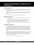
Nucleus® Paging Station I-20 Upgrade 1 Introduction The WMtxp™ protocol by Glenayre is a superset of the standard ERMES I-20 interface protocol. The upgrade to I-20 Nucleus allows the Station Control Module (SCM) in the Nucleus and Nucleus II paging stations to communicate with the GL-C2000/C2010 transmitter controller from Glenayre. The procedures contained in this document cover the removal of the NIU, reference module (if installed), removal and installation of the SCM and Exciter modules, installation of the I-20 cable, and configuration of the Nucleus or Nucleus II paging station to work with the GL-C2000/C2010 transmitter controller. The I-20 interface cable connects to the front of the SCM from the rear of the paging station. The I-20 interface is used only with SCM model number PTYN4059B or later. Earlier SCM models do not have the I-20 interface connector. The interface cable may be installed in a low or high power Nucleus paging station. Procedures are provided for the installation on both Nucleus paging stations. The Exciter module and SCM are a matched pair and have been aligned at the factory. They must be installed as a matched pair the same station at the same time. Note: Read this entire upgrade procedure prior to beginning the installation. Unpacking and Inspection 1. Inspect the shipping container for any external damage, and report or record as required by company standard operating procedures (SOP). 2. Open the shipping carton and save the box and packing materials for defect return, if applicable. 3. Verify that you received the proper kit and that the kit contains all parts required for the upgrade (see Table 1). 4. Visually inspect the equipment. June 1998 6881100F56-C Preliminary 1 Nucleus® Paging Station I-20 Upgrade Field Replaceable Unit Required Equipment The contents of the I-20 upgrade kit depend on the frequency of the Nucleus paging station being upgraded. Table 1 lists the equipment for each upgrade kit. Table 1: Upgrade Parts List for I-20 If your Nucleus is: ...to upgrade to I-20, order: Part Number - Matched Pair FRU 900 MHz - I-20 BSC Cable (if Glenayre) - BNC T connector and 50 ohm male terminator - Matched Pair FRU 280 MHz - I-20 BSC Cable (if Glenayre) - BNC T connector and 50 ohm male terminator - Matched Pair FRU VHF R1 (132–154 MHz) - I-20 BSC Cable (if Glenayre) - BNC T connector and 50 ohm male terminator - Matched Pair FRU VHR R2 (150–174 MHz) - I-20 BSC Cable (if Glenayre) - BNC T connector and 50 ohm male terminator - Matched Pair FRU UHF 1. 2 - I-20 BSC Cable (if Glenayre) - BNC T connector and 50 ohm male terminator - PTTF1029A (includes PTKN4117A with 3086144G03, PTTF1013A, PTGN4029A1, and PTYN4059B) - PTKN1003A (includes 3086453G02) - PTLN4450A (includes 0909907D01 and 0909906D01) - PTTF1030A (includes PTKN4117A with 3086144G03, PTTD1001A, PTGN4029A1, and PTYN4059B) - PTKN1003A (includes 3086453G02) - PTLN4450A (includes 0909907D01 and 0909906D01) - PTTF1031A (includes PTKN4117A with 3086144G03, PTTD1003A, PTGN4029A1, and PTYN4059B) - PTKN1003A (includes 3086453G02) - PTLN4450A (includes 0909907D01 and 0909906D01) - PTTF1032A (includes PTKN4117A with 3086144G03, PTTD1002A, PTGN4029A1, and PTYN4059B) - PTKN1003A (includes 3086453G02) - PTLN4450A (includes 0909907D01 and 0909906D01) - PTTF1033A (includes PTKN4117A with 3086144G03, TLE9082D, PTGN4029A1, and PTYN4059B) - PTKN1003A (includes 3086453G02) - PTLN4450A (includes 0909907D01 and 0909906D01) The Exciter front panel is shipped installed on the Exciter. 6881100F56-C Preliminary June 1998 Nucleus® Paging Station I-20 Upgrade Field Replaceable Unit Additional equipment is required for the upgrade: • • Nucleus Paging Station Configuration for Operation with the Glenayre Transmitter Controller, document number 6881100F63 GL-C2010, Version 3.1, Transmitter Controller User Manual, document number 9110.00930 Rev:1.1 (or later) • Personal computer (PC) with PROCOMM software (or equivalent terminal software) • Service monitor, Motorola R2600 or equivalent • Null modem cable • Straight-through cable • TORX driver with a T15 TORX bit • 10-mm nut driver or adjustable wrench • Electrostatic wrist strap • Antistatic work surface June 1998 6881100F56-C Preliminary 3 Nucleus® Paging Station I-20 Upgrade Field Replaceable Unit Preinstallation The Nucleus paging station must be powered down completely for the installation of the I-20 protocol cable. This procedure should be accomplished during a low usage time period to prevent interruption of paging services. Read this entire procedure prior to attempting to install the I-20 upgrade kit. Current Configuration Settings The SIMM located on the TRN7815 Station Control Board (SCB) is set for customer-specific parameters, such as channel frequency and power output. Using the control panel key pad, log the current station configuration parameters in the table provided (see Table 3) so the parameters can be reconfigured into the new PTYN4059B SCM after installation. While logging the station parameters, set Paging Access to disable. Control Panel Keypad Functions The keypad has 15 keys (see Figure 1-2). The top 12 keys serve two functions: • Menu functions (in the menu select mode) • Date entry functions (in the edit mode) Three keys at the bottom of the keypad provide additional control. Menu Select Mode The menu select mode accesses a station menu or submenu (see Figure 1-2). The station is in the menu select mode when the LED display shows the READY prompt. In this mode, any key has the value of a menu option. Press a key to select a menu. Press <up arrow>, <down arrow>, or <TOG> to move from one menu to another. Press <EXIT> to return to the previous menu level. Edit Mode The edit mode adds or modifies data in station memory. The station is in the edit mode when the LED display is flashing. In this mode any key has the value of the number on it. Enter values as appropriate. Press <ENT> to store a value. Note: 4 If you toggle to the menu select mode without storing the value, the system uses the previously entered value. 6881100F56-C Preliminary June 1998 Nucleus® Paging Station I-20 Upgrade Field Replaceable Unit Reset 1 2 STN RX 4 OPT1 7 STAT 5 OPT2 8 CNFG Reset 3 Pressing the 1/STN and 3/TX keys simultaneously causes the station to reinitialize, perform power-up diagnostics and resets all RAM values to their default settings. TX 6 ASET 9 ALMS 1 STN 3 TX 5 OPT2 7 STAT 9 ALMS SERV DIS ALGN EXIT TOG ENT 2F05SRH-29 0 SERV Edit Mode: Press to enter value of 1. Menu Select Mode: Use STN to set up station parameters. 2 Edit Mode: Press to enter value of 3. Menu Select Mode: Use TX to set up parameters for transmitting. 4 Edit Mode: Press to enter value of 5. Menu Select Mode: Use OPT 2 for access to communication option parameters. Edit Mode: Press to enter value of 7. Menu Select Mode: Use STAT to display station status. Edit Mode: Press to enter value of 9. Menu Select Mode: Use ALMS to view alarms, clear alarms, or both. Edit Mode: Press ▲ to move up to the next menu selection. Menu Select Mode: Use SERV to enter the service mode or key and read power. EXIT Use EXIT to return to the READY mode, move upward one menu level, or abort an edit session. ENT Use ENT to store keyed-in values, move inward one menu level, or begin an edit session. RX OPT1 6 ASET 8 CNFG 0 DIS ALGN TOG Edit Mode: Press to enter value of 2. Menu Select Mode: Use RX to set up parameters of the received audio and receiver applications. Edit Mode: Press to enter value of 4. Menu Select Mode: Use OPT 1 to access station option parameters. Edit Mode: Press to enter value of 6. Menu Select Mode: Use ASET to set up alarms. Edit Mode: Press to enter value of 8. Menu Select Mode: Use CONFG to setup and view configuration parameters. Edit Mode: Press to enter value of 0. Menu Select Mode: Use DIS to disable remote keyup while allowing local keyup; also to view disable status. Edit Mode: Press ▼ to move down to the next menu selection. Menu Select Mode: Use ALGN to perform station alignment. Use TOG to change values or selections. Figure 1-2: SCM and NAC Front Panel Keypad June 1998 6881100F56-C Preliminary 5 Nucleus® Paging Station I-20 Upgrade Field Replaceable Unit Table 3: Station Configuration Parameters (Sheet 1 of 3) Parameter Current Reading STN-Station System Timer Alrm Disable 60 Min 2 Min 90 Min 15 Min 120 Min 30 Min 180 Min Front Panel Password Enabled Disabled Factory Default Password 6000 TX-Transmit Channel Freq CHN 1 FREQ ______________ CHN 11 FREQ _____________ CHN 2 FREQ ______________ CHN 12 FREQ _____________ CHN 3 FREQ ______________ CHN 13 FREQ _____________ CHN 4 FREQ ______________ CHN 14 FREQ _____________ CHN 5 FREQ ______________ CHN 15 FREQ _____________ CHN 6 FREQ ______________ CHN 16 FREQ _____________ CHN 7FREQ _______________ CHN 17 FREQ _____________ CHN 8 FREQ ______________ CHN 18 FREQ _____________ CHN 9 FREQ ______________ CHN 19 FREQ _____________ CHN 10 FREQ _____________ CHN 20 FREQ _____________ TX Deviation Setup Nominal Binary Deviation _____________________ Special TX Setup TX=Data Invert Enabled Disabled TX=EQ RX State Enabled Disabled 6 6881100F56-C Preliminary June 1998 Nucleus® Paging Station I-20 Upgrade Field Replaceable Unit Table 3: Station Configuration Parameters (Sheet 2 of 3) Parameter Current Reading CFG-Station Configuration Operating PWR ________________________ Battery Revert Setup Battery Type Sealed Lead Calcium Battery Revert Disabled Backup Backup Station (low Power Only) Backup Control EXT Wattmeter Type None EXT Class 1 Control External SYNC Local CTRL Special Key Select EXT High (Preferred) OPT1-Station Antenna Relay Enabled (Preferred) EXT Circulator Present Not Present STAT-Station Status Software Versions Application ________________ Exciter ____________________ BOOT ____________________ Alignment ID SCM _____________________ Exciter ___________________ June 1998 6881100F56-C Preliminary 7 Nucleus® Paging Station I-20 Upgrade Field Replaceable Unit Table 3: Station Configuration Parameters (Sheet 3 of 3) Parameter Current Reading DIS-Access Disable Maint Access Enabled (to perform Maint) Disabled (to TX & Page) Note: Paging Access must be set to disable. Paging Access Enabled (to TX & Page) Disabled (to perform Maint) SCM and NIU Removal Removal of the SCM is necessary to install the I-20 upgrade kit. With the installation of the I-20 upgrade kit, there is no need for the NIU. If a reference module is currently installed, remove the module and Global Positioning System (GPS) cable. Removal of the modules are covered in this procedure: 1. Disconnect the I-20 transmitter controller from the network. 2. If the station has AC power with a battery revert option (X30 or X43), disconnect the batteries by removing the positive (+) lead from the positive (+) battery terminal. 3. At the front of the paging station, place the ON/OFF power switch on the power supply(s) in the off (0) position (see Figure 1). 4. Plug your wrist strap into one of the receptacles located on either side of the station chassis. 5. Using a TORX driver with a T15 TORX bit, remove the two screws securing the control panel of the Nucleus paging station to the chassis (see Figure 1). Electronic devices are susceptible to damage from electrostatic discharge. Failure to use an approved electrostatic wrist strap may result in equipment damage. CAUTION 6. Remove the control panel and disconnect the control cable from the control panel. 7. Using the control panel, insert the rear flange of the control panel in the slot of the SCM (see Figure 2) and gently pull the SCM out of the chassis. Note: 8. 8 Skip Step 8 through Step 11 if the SCM does not contain a CRIB daughter board. Place the SCM module component side down on an antistatic surface. 6881100F56-C Preliminary June 1998 Nucleus® Paging Station I-20 Upgrade 9. Field Replaceable Unit Using a screwdriver or equivalent tool, gently press the four posts holding the CRIB daughter board out of the SCM board (see Figure 3). 10. Obtain the new SCM board and place on a antistatic work surface or antistatic bag. 11. Align the connector pins of the CRIB with the connector on the SCM. Align the four mounting posts of the CRIB with the matching holes in the New SCM board and firmly press in place. Note: IF the I-20 cutover is not going to be accomplished immediately after completion of this installation procedure, skip Step 13 through Step 15. 12. At the rear of the station chassis, open the fan cowling. 13. Remove the C-LAN cable from the NIU (if connected). 14. Using the control panel, insert the rear flange of the control panel in the slot of the NIU module (see Figure 2) and gently pull the NIU out of the chassis. 15. Place the NIU on a protected antistatic work surface or antistatic bag for proper storage. June 1998 6881100F56-C Preliminary 9 Nucleus® Paging Station I-20 Upgrade Field Replaceable Unit RF Cable TORX Screw POWER AMPLIFIER EXCITER Low Power POWER SUPPLY CONTROL REFERENCE RECEIVER A 1 2 3 4 5 6 7 8 9 0 TX LOCK PA PULL EXIT TOG ENT PA LOW ON PA FAIL FAIL STBY ALARM DISCONNECT battery if battery equipped and turn OFF power supply before removing or inserting any module. 0FXXSRH-05 WARNING REF FAIL ON PORT Power Switch RF Cable POWER SUPPLY Control Panel TORX Screw TORX Screw EXCITER POWER SUPPLY CONTROL REFERENCE 1 2 3 4 5 6 7 8 9 TORX Screws for Cover RECEIVER 0 TX LOCK PA PULL EXIT TOG ENT PA LOW ON PA FAIL FAIL STBY ALARM WARNING FAIL FAIL ON ON DISCONNECT battery if battery equipped and turn OFF power supply before removing or inserting any module. 0FXXSRH-05a WARNING DISCONNECT battery if battery equipped and turn OFF power supply before removing or inserting any module. REF PORT Power Switch High Power TORX Screw Figure 1: Typical Nucleus Paging Station 10 6881100F56-C Preliminary June 1998 Nucleus® Paging Station I-20 Upgrade Field Replaceable Unit 405SRH-03 Cover Plate Notch Board-Pulling Arm Figure 2: SCM and NIU Removal I-20 Cable and Bracket Assembly (PTKN4117A) SCM I-20 Connector 0F12SRH-30b Control Panel Ribbon Connector LEDs Connector Pins CRIB Connector Standoff Posts Figure 3: Station Control Module, Part Number PTYN4059B With I-20 Cable and CRIB June 1998 6881100F56-C Preliminary 11 Nucleus® Paging Station I-20 Upgrade Field Replaceable Unit Reference Module Removal Remove the reference module from the paging station, if it is installed, as follows. 1. At the front of the paging station, remove the two TORX screws securing the reference module to the chassis using a TORX driver and a T15 bit (see Figure 1). 2. Grasp the handle of the reference module and pull the module partially out of the chassis. 3. Disconnect the RF cable (if present) from the reference module and pull the module out of the chassis. 4. Replace the reference module cover on the chassis: a. Using a TORX driver and a T15 bit, remove the cover from the reference module. b. Place the reference module cover in position on the chassis and secure in place using the two screws removed in Step 1. 5. At the rear of the paging station, pull the RF cable out through the backplane opening of the station. 6. Using a 10 mm nut driver or an adjustable wrench, remove the nut securing the ground cable to the ground lug on the antenna relay mounting bracket (see Figure 4). 7. Using a 10 mm nut driver or an adjustable wrench, remove the nut securing the antenna relay mounting bracket to the chassis (see Figure 4). 8. Remove the GPS RF cable (if present): 9. a. Use a TORX driver and a T15 bit to remove the two screws securing the GPS RF cable to the antenna mounting bracket. b. Place the cable and screws to the side for proper disposal. Place the antenna mounting bracket in position on the backplane and secure in place with the 10 mm nut removed earlier (see Figure 4). 10. Place the ground cable connector in position on the ground lug and secure in place with the 10 mm nut removed earlier (see Figure 4). Exciter Module Removal 12 1. Using a TORX driver with a T15 TORX bit, remove the two screws securing the Exciter module to the chassis (see Figure 1). 2. Remove the RF cable from the connector on the Exciter module. 3. Grasp the handle on the Exciter module and carefully pull the Exciter module out of the chassis. 4. Place the Exciter module to the side on a protected antistatic work surface or antistatic bag. 6881100F56-C Preliminary June 1998 Nucleus® Paging Station I-20 Upgrade Field Replaceable Unit Two Screws View A—Low Power Paging Station With Peripheral Bracket In Out Load 10 MHz Reference From C2000/C2010 50 Ohm Terminator 2F05SRH-13a J30 Cable Entry Slot T-Connector Two New Screws View B—Low Power Paging Station Without Peripherals I-20 Mounting Bracket/Connector Antenna Relay Mounting Bracket 10 mm Nut J30 2F05SRH-26b 27 10 MHz Reference From C2000/C2010 50 Ohm Terminator Ground Lug T-Connector Two Screws View C—High Power Paging Station With Peripheral Bracket In 10 MHz Reference From C2000/C2010 Out Load 50 Ohm Terminator Note: View B is shown without the peripherals to indicate where the I-20 bracket is located. Only the low power is shown without the peripherals, but the bracket for the high power Nucleus paging station is mounted in the same manner. 2F05SRH-13 J30 T-Connector Cable Entry Slot Figure 4: Nucleus Paging Station (Rear View) June 1998 6881100F56-C Preliminary 13 Nucleus® Paging Station I-20 Upgrade Field Replaceable Unit I-20 Upgrade Kit Installation The I-20 upgrade kit contains a cable attached to a mounting bracket, an SCM board, and an Exciter module (matched pair). Install the kit using the following procedures. SCM and I-20 Interface Cable Installation The cable mounting bracket mounts to the rear connector panel of the Nucleus paging station. The I-20 interface cable is fed through the rear of the chassis into the slot normally occupied by the SCM. Install the I-20 interface cable kit as follows: 1. At the rear of the paging station, remove the two screws located below the cable entry slot using a TORX driver with a T15 TORX bit (see Figure 4). Discard the two screws. 2. Insert the connector end of the cable kit through the slot in the chassis. 3. Attach the I-20 mounting bracket (part of PTKN4117A cable and bracket assembly) to the chassis with the two black screws provided in the cable and bracket assembly using a TORX driver with a T15 TORX bit. 4. At the front of the paging station, insert the rear of the SCM into the mounting slots of the chassis and slide it half way into the chassis. 5. With the SCM halfway into the chassis, connect the I-20 cable (part 3086144G03 cable and bracket assembly) to the I-20 interface connector located on the SCM (see Figure 3). Ensure the SCM cable is properly seated by listening for a slight click as the connector is seated. CAUTION 14 Ensure the cable is securely seated in the SCM board connector. Failure to ensure proper connection will cause improper operation. 6. With the I-20 cable connected to the I-20 SCM connector, carefully slide the SCM into the chassis and firmly into the backplane connector to ensure proper connection. 7. Connect the ribbon cable of the control panel to the connector on the front of the SCM (see Figure 3). 8. Install and secure the control panel in position on the chassis with the two TORX screws removed in paragraph, "SCM and NIU Removal", Step 5 using a TORX driver with a T15 TORX bit (see Figure 1). 6881100F56-C Preliminary June 1998 Nucleus® Paging Station I-20 Upgrade Field Replaceable Unit Exciter Module Installation Install the new Exciter module (part PTTF1013A with PTGN4029A front panel) as follows: 1. At the front of the paging station, insert the replacement Exciter module in the slot provided. 2. Slide the Exciter module half way into the chassis. 3. Connect the RF cable removed in paragraph, "Exciter Module Removal", Step 2 to the RF connector on the Exciter module. Make sure the male/female connectors are properly aligned before tightening. 4. Push the Exciter firmly into the backplane connector. 5. Secure the Exciter in the chassis with two TORX screws using a TORX driver with a T15 TORX bit (see Figure 1). I-20 Transmitter Controller Connection Connect the Nucleus paging station to the I-20 (Glenayre GL-C2000/C2010) transmitter controller as follows: 1. At the rear of the paging station, connect the I-20 BSC interface cable (15-pin connector), part number 3086453G02 (a component of PTKN1003A) to the SCM I-20 connector (see Figure 4). 2. Connect the other end of the I-20 interface cable (44-pin connector) to the I-20 transmitter controller Exciter connector [see GL-C2000/C2010 Transmitter Controller Version 3.1 User Manual (software version 3.1 or later) for location of the Exciter connector]. 3. Connect the center connector of the T-Connector with the 50 ohm terminator to J30 on the backplane (see Figure 4). 4. Connect the 10 MHz reference cable to the open end of the T-Connector on the rear of the paging station (see Figure 4). 5. Place the On/Off switch located on the power supplies of the paging station in the on (|) position. Note: 6. If the station has a battery revert option, reconnect the batteries. Note: June 1998 The LEDs located on the SCM and the Exciter module momentarily flash on and off except for the On LED of the SCM. If the Glenayre wattmeter option is desired, the station external wattmeter option must be disabled. 6881100F56-C Preliminary 15 Nucleus® Paging Station I-20 Upgrade Field Replaceable Unit Repackaging and Returning Defective Equipment Defective equipment is due back a Motorola within two weeks of receipt of replacement equipment. To return defective equipment, follow these steps: 1. Pack and return the defective assembly in the same packing and box from the replacement module. 2. Include a copy of the return material authorization (RMA) or repair authorization (RA) paperwork in the box. 3. Mark the RMA or RA number on the outside of the box. 4. Ship the package to the following address: Motorola Warranty 5401 North Beach Street Fort Worth, Texas, USA 76137-2794 Note: 16 You must provide a purchase order for the price of the replacement assembly for defective equipment not returned within two weeks. 6881100F56-C Preliminary June 1998 Nucleus® Paging Station I-20 Upgrade Field Replaceable Unit Motorola Service Refer questions concerning the contents of this manual or requests for related circuit board information to the following location: Motorola, Inc. Paging Systems Group Multimedia Publications Department 5401 North Beach St., MS E230-A Fort Worth, TX 76137-2794 or telephone: (817) 245-2824 For service information, contact your local Motorola representative or the Paging One-Call-Support Center: Motorola, Inc. Paging One-Call-Support Center 5401 North Beach St., MS E112 Fort Worth, TX 76137-2794 telephone: facsimile: (800) 520-7243 or (817) 245-4663 (817) 245-2141 electronic mail: [email protected] Motorola is not responsible for static damage to equipment not sold under the Motorola logo. Motorola, the Motorola logo, Nucleus, and FLEX are registered trademarks of Motorola, Inc. Glenayre is a registered trademark of Glenayre Technologies, Inc. WMtxp is a trademark of Glenayre Technologies, Inc. TORX is trademark of Textron Inc. Trademarks contained herein are the acknowledged property of their respective owners. Motorola, Inc. 1998. All rights reserved. Printed in the U.S.A. June 1998 6881100F56-C Preliminary 17 1998 Motorola, Inc.