1
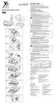
Side
Side
Side
B ENGLISH
Electromagnetic Compatibility
Standards (EMC)
Associated Manuals
MODEL
MANUAL Number
Date
FX2N-64CL-M
JY997D05401F
SEPTEMBER 2008
CAUTION
may also be linked to serious ramifications.
It is important to follow the directions for usage.
• CC-Link/LT network wiring uses the CC-Link/LT connection cable specified by
CC-Link Partner Association (CLPA), and perform wiring in accordance with
the specifications described in this manual.
If any cable other than the connection cable is used or if wiring is performed
in a method not conforming to the specifications, normal data transmission
cannot be assured.
• Do not bind the CC-Link/LT connection cable together with major circuits or
power cables. Keep the connection cable away from major circuits and power
cables by 100 mm (3.93") or more.
It may cause malfunction due to noise interference.
• Accommodate the CC-Link/LT connection cable inside a duct, or fix it with
clamps.
If the connection cable is loose or is pulled for movement or carelessness, the
master block and the connection cable may be damaged or malfunction due
to imperfect connection.
• Correctly wire the master block while confirming the rated voltage and
terminal arrangement of the master block. It may cause fire or product failure.
• Hold the connector area when disconnecting the CC-Link/LT connection
cable from the master block.
If the cable area is pulled, the master block or the dedicated cable may be
damaged or malfunction.
[DESIGN PRECAUTIONS]
[STARTING AND MAINTENANCE PRECAUTIONS]
●SAFETY PRECAUTIONS●
This manual describes the name of each part, external dimensions and
specifications of the CC-Link/LT master block for the Mitsubishi FX series
Programmable Logic Controller (PLC).
For the design and construction of the CC-Link/LT system, refer to the CCLink/LT Master Block Users Manual.
These ●SAFETY PRECAUTIONS● are classified into two categories:
"DANGER" and "CAUTION".
Procedures which may lead to dangerous conditions or
cause minor to medium injury, or physical damage, if
not carried out properly.
Depending on certain circumstances, procedures indicated by
CAUTION
CAUTION
Handling Cautions
-
4
-
3
16pts.
1
4pts.
B RATE
3.1 Mounting direction
• Do not install the master block on the floor, ceiling or in the horizontal
direction within the cabinet. If the master block is installed in such a way,
its temperature may rise.
Install the master block vertically on the back wall of the cabinet as shown
in the figure below.
• Leave a space of 50 mm (1.96") or more between the master block and
other equipment or structure. Keep the master block off high voltage
cables, high voltage equipment and other power equipment as much as
possible.
This notification does not guarantee that an entire mechanical module produced
in accordance with the contents of the notification comply with the following
standards. Compliance to EMC standards of the entire mechanical module
should be checked by the user / manufacturer.
Standards with which this product complies
Type : Programmable Controller (Open Type Equipment)
Models : Products manufactured:
from February 1st, 2003 to April 30th, 2006 are compliant with
EN61000-6-4 and EN61131-2:1994+A11:1996+A12:2000
after May 1st, 2006 are compliant with EN61131-2:2003
Electromagnetic Compatibility
Remark
Standards (EMC)
Compliance with all relevant aspects of
EN61000-6-4:2001
the standard.
Electromagnetic compatibility
(Radiated Emissions and Mains Terminal
-Generic standards - Emission
standard for Industrial environment Voltage Emissions)
Compliance with all relevant aspects of
EN61131-2:1994/A11:1996/A12:2000
the standard.
Programmable controllers
(RF Immunity, Fast transients, ESD and
-Equipment requirements and tests
Damped oscillatory wave)
Extension connector
to extension block/unit
or special function
block/unit of the PLC
Connector for
CC-Link/LT interface
Specifications
Item
Operating
temperature
0 to 55°C (32 to 131°F)
Storage
temperature
-20 to 70°C (-4 to 158°F)
Operating
humidity
35 to 85%RH (Condensation should not be allowed.)
Number of times of
sweep
Direct mounting
Acceleration Half amplitude
−
Align the upper DIN rail installation groove in the module with the DIN rail
1), and press the module on to the DIN rail 2).
When removing the module, pull the installation hook downwards 3), and
remove the module 4).
DIN rail mounting screw pitch
When mounting the module on the DIN rail, tighten the mounting screws at
a pitch of 200 mm (7.87") or less.
Removal
1)
4)
−
147 m/s2, working time: 11 ms, half sine wave, three times in
the X, Y and Z directions
Noise immunity
By noise simulator of noise voltage = 1,000 Vp-p,
noise width = 1 µs, rising = 1 ns, cycle = 30 to 100 Hz
Dielectric
withstand
voltage
500V AC for 1 min
Isolation
resistance
Operating
ambience
5 MΩ or more by 500V
DC megger
Do not use in environment with corrosive gas, flammable gas
or conductive dusts.
5.2 Network wiring specifications
Item
Specification
Communication
speed
2.5Mbps
Distance between
stations
625kbps
• The connection order of the CC-Link/LT connection cable has no
relevance to the station No.
• Make sure to install the master block on one side of the trunk line.
• In the CC-Link/LT system, terminating resistors should be connected to
both ends of the trunk line.
Connect the terminating resistor on the master block side within 200 mm
(7.87") of the master block.
• For the CC-Link/LT connection cable point of contact, the connection
cable connector and terminating resistors, refer to the homepage of the
CC-Link Partner Association (CLPA) "http://www.cc-link.org/".
Remarks
156kbps
--
No restriction
--
8 units
--
35m
(114' 9")
Maximum trunk
length
Maximum drop
length
Connect the master block to a remote I/O unit or power adapter using the
connection cable and the dedicated CC-Link/LT connector.
In conformance to JEM-1021
Between case and PLC grounding
terminal
*1 Do not use the PLC under pressure higher than the atmospheric pressure.
Doing so may damage the PLC.
3.3 Direct mounting
Connection of External Equipment
4-point mode and 16-point mode
(selectable by DIP switch)
Maximum number of link
points
100m
(328' 1")
500m
Cable length between
(1640' 5") terminating resistors
No restriction
--
4m(13' 1")
16m
(52' 5")
60m
Cable length per
(196' 10") branch
15m
(49' 2")
50m
(164' 0")
200m
Sum of all drop lines
(656' 2")
Cumulative drop line
length
Number of link points per
station
( ) shows the number of link
points when composite I/O
module is used.
Terminating
resistor
Power
adapter
Drop length
(including branch)
Remote
I/O station
Remote
I/O station
Distance between
stations
Trunk line
Drop line
Remote
I/O station
Terminating
resistor
16 points (32 points)
1.0ms
0.7ms
2.2ms
3.8ms
156kbps
8.0ms
14.1ms
2.0ms
2.5Mbps
1.2ms
64 stations 625kbps
4.3ms
7.4ms
156kbps
15.6ms
27.8ms
2.5 Mbps, 625 kbps and 156 kbps
(selectable by DIP switch)
BITR method
(Broadcastpolling +
Interval Timed Response)
Protocol
T-branch
Network topology
CRC
Error control method
Number of connected stations
1 to 64
Connected at the end of the trunk line
Communication error detection, automatic
return to system, slave station
disconnection and internal loop back
diagnosis
RAS function
• Dedicated flat cable (0.75 mm2 x 4)
Connection cable
• VCTF cable (0.75 mm2 x 4)*4
• High flexible cable (0.75 mm2 x 4)
8 points (fixed) +
Number of connected remote I/O points
190 mA
(Supplied from PLC via extension
Current consumption inside 5V DC
connector)
Number of occupied I/O points
24V DC power
supply
Mass (weight)
20.4V to 28.8V DC
Current
consumption
25 mA
Initial current
35 mA
Supplied from power
adapter via
CC-Link/LT interface
connector.
0.15 kg (0.33 lbs)
*1 When connected to the FX1N Series PLC, up to two FX2N-64CL-M units can be
connected to the main unit and another two on the extension unit.
Remote
I/O station
Remote
I/O station
Remote
I/O station
SW1
OFF
SW2
OFF
625 kbps
ON
OFF
2.5 Mbps
OFF
ON
Setting disabled
ON
ON
Point mode setting
(Select the number of I/O points per station.)
OFF :4-point mode (4 input points and 4 output points
in each station)
ON :16-point mode (16 input points and 16 output
points in each station)
16pts/
4pts
4
--
Setting is disabled.
(Make sure that this is OFF during operation.)
5
--
Setting is disabled.
(Make sure that this is OFF during operation.)
6
CONFIG/
ONLINE
CONFIG mode
OFF :ONLINE mode (normal operation)
ON :CONFIG mode (The information on connected
stations is saved in the EEPROM.)
7
TEST/
ONLINE
TEST mode
OFF :ONLINE mode (normal operation)
ON :TEST mode (Self-loop back Test)
8
--
Setting is disabled.
(Make sure that this is OFF during operation.)
• Factory default, all bits of the DIP switch are set to OFF.
• Test mode is selected when both the CONFIG and TEST modes are set
to ON simultaneously.
• For each setting, the status at time of power ON is valid.
(If a setting is changed after the power is turned ON, the change is
invalid.)
CONFIGMODE
• BFM #32 (20h) to #95 (5Fh) changed value while online will cause a
L ERR.
• If no remote modules are attached during power ON, no L ERR shown.
• If a remote module is removed during operation, no L ERR will be shown.
External Dimensions
2-φ4.5(0.18)
RUN
ERR.
L RUN
L ERR.
SD
RD
POWER
FX2N-64CL-M
43(1.70)
87(3.43)
This manual confers no industrial property rights or any rights of any other kind, nor
does it confer any patent licenses. Mitsubishi Electric Corporation cannot be held
responsible for any problems involving industrial property rights which may occur as
a result of using the contents noted in this manual.
Warranty
Mitsubishi will not be held liable for damage caused by factors found not to be the
cause of Mitsubishi; opportunity loss or lost profits caused by faults in the Mitsubishi
products; damage, secondary damage, accident compensation caused by special
factors unpredictable by Mitsubishi; damages to products other than Mitsubishi
products; and to other duties.
64 stations maximum
Remote station numbers
Master station connection
position
Communication speed
156 kbps
Unit: mm(inches)
4 points (8 points)
2.5Mbps
Voltage
Trunk length (branch line length not included)
T branch
Master station
T-branch interval
connection
16-point mode
Connected to FX1N Series PLC: 128 points
Connected to FX2N/FX2NC/FX3U/FX3UC
Series PLC: 256 points
(including I/O points in PLC in each case)
32 stations 625kbps
Communication speed
Working altitude < 2000m*1
Grounding resistance 100Ω or less (Common grounding with
Grounding
strong electrical systems is not allowed.)
T-branch interval
M4 height: 16mm(0.63") or more
(Tightening torque range: 0.78 to 1.08 N⋅m)
Applicable point mode
4-point mode
Shock
resistance
Applicable DIN rail TH35-7.5Fe and TH35-7.5AI
Fix the master block on the panel surface by tightening the M4 screws
inserted
in the two (upper and lower) mounting holes provided on the master block.
Install the module so that a clearance of 1 to 2mm (0.04" to 0.08") is
assured for each module.
FX1N Series : Up to 4 *1
FX2N/FX3U/FX3UC Series: Up to 8 *2*3
FX2NC Series: Up to 3 *2
−
10 times in the X, Y
DIN rail mounting
and Z directions (for
Frequency Acceleration Half amplitude 80 min)
10 to 57Hz
0.035mm
−
Maximum number of
modules connected
in 1 drop line
3)
Number of connectable master
blocks
0.075mm
3
4(0.16)
FX1N/FX2N/FX2NC/FX3U/FX3UC Series PLC
(FX2NC-CNV-IF is required when FX2NC
Series PLC is connected.)
(FX2NC-CNV-IF or FX3UC-1PS-5V is
required when an FX3UC Series PLC is
connected.)
Applicable PLC
57 to 150Hz 9.8m/s2
CC-Link/LT connection cable connector
(24G/DB/DA/+24 V)
B RATE
Specification
Specification
10 to 57Hz
<ONLINE mode/CONFIG mode/TEST mode>
ON: Data is being received
1
6.
5.3 Performance specifications
57 to 150Hz 4.9m/s2
3.2 DIN rail mounting
Description
<ONLINE mode/CONFIG mode/TEST mode>
ON: Power is being supplied
OFF:Power is not being supplied
<ONLINE mode>
ON: Master block is operating normally
OFF:Master block is abnormal
Power has been interrupted
EEPROM read error (sum mismatch) occurred
<CONFIG mode>
ON: Master block is operating normally
OFF:Master block is abnormal
Power has been interrupted
<TEST mode>
ON: Master block is operating normally
OFF:Master block is abnormal
Power has been interrupted
<ONLINE mode>
ON: Communication speed setting error occurred
EEPROM read error (sum mismatch) occurred
Flickering:Power supplied for communication is abnormal
DIP switch for operation setting was changed
during operation
OFF:Master block is operating normally
<CONFIG mode>
ON: Communication speed setting error occurred
EEPROM write error occurred
Flickering:Power supplied for communication is abnormal
DIP switch for operation setting was changed
during operation
OFF:Master block is operating normally
<TEST mode>
ON: Communication speed setting error occurred
Flickering:Power supplied for communication is abnormal
DIP switch for operation setting was changed
during operation
OFF:Master block is operating normally
ERR.
5.1 General specifications
Vibration
resistance
RD.
Communication speed setting
Hook for installation to DIN rail
Name
RUN
Item
<ONLINE mode/CONFIG mode/TEST mode>
ON: Data is being sent
Interface
Extension cable
connected to PLC
DANGER
Frequency
Status indicator LEDs
FX2N-64CL-M
• Do not disassemble or modify the master block. Doing so may cause failure,
malfunction, injury, or fire.
• The case of the master block is made of resin. Do not drop or apply strong
impacts to the master block.
5.
The master block can be mounted on a DIN rail or directly with screws.
The installation procedure in each case is described below.
Use the master block without applying any force on the cable.
4.
ONLINE
-
2
POWER
●Notification of CE marking●
• Use the master block in the environment described in this manual.
If the master block is used in an improper environment, then electrical
shock, fire, malfunction, product damage or product deterioration may
occur.
• Securely fix the master block with DIN rail or mounting screws. When
using mounting screws, securely tighten them within the specified torque
range.
If the screws are too loose, the module may detach from its installed
position, short circuit, or malfunction. If the screws are too tight, the
screws may be damaged, which may cause the module to detach from
its installed position or short circuit.
Applicable screw
-
TEST
5
CAUTION
• When disposing of this product, treat it as industrial waste.
CAUTION
SD
OFF
-
7
6 CONFIG ONLINE
• Do not touch the terminals when the power is ON. It may cause an electric
shock or malfunction.
• Make sure to shut down all phases of the power supply outside the master
block before starting cleaning. If all phases of the power supply are not shut
down, the master block may be seriously damaged or malfunction.
[INSTALLATION PRECAUTIONS]
2)
ON
8
2
[DISPOSAL PRECAUTIONS]
DANGER
L ERR.
<ONLINE mode>
ON: Station number discrepancy
(when BFM#32(20h) to #95(5Fh) is edited, the
station numbers are checked.)
Outside-control-range station error occurred
Flickering: Stations are abnormal
OFF:Data link is being executed normally
<CONFIG mode>
ON: Station number discrepancy
(when BFM#32(20h) to #95(5Fh) is edited, the
station numbers are checked.)
Flickering: All stations are abnormal
OFF:Data link is being executed normally
<TEST mode>
ON: Self-loop back Test finished abnormally
OFF:Self-loop back Test finished normally
(LED is OFF while the self-loop back Test is being
executed)
DIP switch for operation setting
LINK
• Use the master block without applying any force on the master block and
the CC-Link/LT connection cable.
Otherwise, such cables may break or fail.
• Shut down all phases of the power supply outside the master block, then
attach or remove the master block. If the power is not disconnected at all
phases an electric shock or serious damage to the product may occur.
L RUN
Part Name and Setting
2-φ4.5(0.18") mounting hole
(M4 mounting screw)
Status indicator LEDs
• Construct an interlock circuit in the sequence program so that the
system works correctly using the communication information when an
error in the data link occurs.
If such an interlock circuit is not provided, accidents may be caused by
erroneous output or malfunction.
• When a remote I/O unit fails, inputs/outputs may randomly become ON
or OFF, therefore build an external monitoring circuit that will monitor any
input signals that could cause a serious accident.
Accident may be caused by erroneous output or malfunction.
Installation
2.
DANGER
DANGER
3.
Product Outline
The CC-Link/LT master block FX2N-64CL-M can be connected to the FX Series PLC.
By using this master block, a CC-Link/LT system can be constructed with the FX
Series PLC as the master station.
Control specifications
CAUTION
Procedures which may lead to dangerous conditions or
cause death or serious injury if not carried out properly.
1.
Communication specifications
DANGER
Manual name
Manual No.
Description
CC-Link/LT Master
This manual explains the specifications,
Block Model FX2NJY997D08501 wiring, handling, etc. of the CC-Link/LT
64CL-M User's Manual
master block.
(Detailed Volume)
Description
<ONLINE mode/CONFIG mode>
ON: Data link is being executed
OFF:Data link is stopped
<TEST mode>
ON:Self-loop back Test finished normally
OFF:Self-loop back Test finished abnormally
(LED is OFF while the self-loop back Test is being
executed)
FX2N-64CL-M
DANGER
• Shut down all power supplies, before starting the wiring work. If the power is
not disconnected from all sources an electric shock or serious product
damage may occur.
Status indicator LEDs
[WIRING PRECAUTIONS]
DIP switch for operation setting
User’s Manual (Hardware Volume)
Name
80(3.15)±0.5(0.02)(mounting size)
Please read this manual thoroughly before using the product.
Remark
Compliance with all relevant aspects of
the standard.
(Radiated Emissions, Mains Terminal
EN61131-2: 2003
Voltage Emissions, RF immunity, Fast
Programmable controllers
-Equipment requirements and tests Transients, ESD, Surge, Voltage drops
and interruptions, Conducted and Power
magnetic fields)
For more details please contact the local Mitsubishi Electric sales site.
- Notes For compliance to EMC regulation.
The FX2N-64CL-M must be installed in a shielded metal control panel.
1 2 3 4 5 6 7 8
CC-Link/LT Master Block Model FX2N-64CL-M
• Pay attention that foreign objects such as cuttings or wiring chips do not enter
the master block. It may cause fire, product failure or malfunction.
• During installation and wiring works, adhere dust-proof sheets supplied
together with the master block on the sides of the master block so that foreign
objects such as cutting chips and wiring chips do not enter the inside.
Otherwise, foreign objects may cause fire, failure or malfunction.
• Before operating the system, remove the dust-proof sheets so that heat can
be released. It may cause fire, product failure or malfunction.
90(3.55)
CAUTION
O
N
A JAPANESE
Link scan time
B
*2 FX2N-64CL-M draws 190mA from the 5V DC source.
The total 5V consumption of all special function blocks connected to the main
unit or extension unit must not exceed the 5V source capacity of the system.
(Refer to the Hardware manual of the PLC)
*3 Up to 7 units can be connected to an FX3UC-32MT-LT PLC.
*4 For the VCTF cable specifications, refer to the FX2N-64CL-M USER’S
MANUAL.
For safe use
• This product has been manufactured as a general-purpose part for general
industries, and has not been designed or manufactured to be incorporated in a
device or system used in purposes related to human life.
• Before using the product for special purposes such as nuclear power, electric power,
aerospace, medicine or passenger movement vehicles, consult with Mitsubishi.
• This product has been manufactured under strict quality control. However when
installing the product where major accidents or losses could occur if the product
fails, install appropriate backup or failsafe functions in the system.
Country/Region Sales office/Tel
U.S.A.
Mitsubishi Electric Automation, Inc.
500 Corporate Woods Parkway, Vernon
Hills, IL 60061 U.S.A.
Tel : +1-847-478-2100
Brazil
MELCO-TEC
Av. Paulista 1439, conj.74, Bela Vista CEP:
01311-200 Sao Paulo-SP-Brazil
Tel : +55-11-3285-1840
Germany
Mitsubishi Electric Europe B.V. German
Branch
Gothaer Strasse 8, D-40880 Ratingen,
Germany
Tel : +49-2102-486-0
U.K.
Mitsubishi Electric Europe B.V. UK
Branch
Travellers Lane, Hatfield, Hertfordshire.,
AL10 8XB, U.K.
Tel : +44-1707-276100
Mitsubishi Electric Europe B.V. Italian
Italy
Branch
VIALE COLLEONI 7-20041 Agrate Brianza
(Milano), Italy
Tel : +390-39-60531
Mitsubishi Electric Europe B.V. Spanish
Spain
Branch
Ctra. de Rub 76-80-AC. 420, E-08190 Sant
Cugat del Valles (Barcelona), Spain
Tel : +34-93-565-3131
Mitsubishi Electric Europe B.V. French
France
Branch
25, Boulevard des Bouvets, F-92741
Nanterre Cedex, France
Tel: +33-1-55685568
Mitsubishi Electric Europe B.V. Moscow
Russia
Representative Office
52, bld. 5, Kosímodamianskaya nab,
RU-115054, Moscow, Russia
Tel: +7-495-721-2070
Country/Region Sales office/Tel
Hong Kong
Mitsubishi Electric Automation
(Hong Kong) Ltd.
10th Floor., Manulife Tower, 169 Electric
Road, North Point, HongKong
Tel : +852-2887-8870
China
Mitsubishi Electric Automation
(Shanghai) Ltd.
17F, ChuangXing Financial Center,
No. 288 West Nanjing Road, Shanghai
China 200003
Tel : +86-21-2322-3030
Taiwan
Setsuyo Enterprise Co., Ltd.
6F No.105 Wu Kung 3rd RD, Wu-Ku
Hsiang, Taipei Hsien, 248, Taiwan
Tel : +886-2-2299-2499
Korea
Mitsubishi Electric Automation Korea Co.,
Ltd.
3F, 1480-6, Gayang-Dong, Gangseo-Gu,
Seoul, 157-200, Korea
Tel : +82-2-3660-9552
Singapore
Mitsubishi Electric Asia Pte, Ltd.
307 Alexandra Road #05-01/02
Mitsubishi Electric Building,
Singapore 159943
Tel : +65-6470-2460
Thailand
Mitsubishi Electric Automation (Thailand)
Co., Ltd.
Bang-Chan Industrial Estate No.111,
Soi Serithai 54, T.Kannayao, A.Kannayao,
Bangkok 10230
Tel : +66-2-517-1326
India
Messung Systems Pvt. Ltd.
Sapphire House EL-3 J-Block MIDC
Bhosari Pune 411026, India
Tel : +91-20-27102000
Australia
Mitsubishi Electric Australia Pty. Ltd.
348 Victoria Road, Rydalmere, N.S.W
2116, Australia
Tel : +61-2-9684-7777
South Africa Circuit Breaker Industries Ltd.
Private Bag 2016, ZA-1600 Isando,
South Africa
Tel : +27-11-9282000
HEAD OFFICE : TOKYO BUILDING, 2-7-3 MARUNOUCHI, CHIYODA-KU, TOKYO 100-8310, JAPAN
HIMEJI WORKS : 840, CHIYODA CHO, HIMEJI, JAPAN
When exported from Japan, this manual does not require application to the Ministry of Economy,
Trade and Industry for service transaction permission.
Specifications subject to change without notice.
Side
Side
Side
B ENGLISH
Electromagnetic Compatibility
Standards (EMC)
Associated Manuals
MODEL
MANUAL Number
Date
FX2N-64CL-M
JY997D05401F
SEPTEMBER 2008
CAUTION
may also be linked to serious ramifications.
It is important to follow the directions for usage.
• CC-Link/LT network wiring uses the CC-Link/LT connection cable specified by
CC-Link Partner Association (CLPA), and perform wiring in accordance with
the specifications described in this manual.
If any cable other than the connection cable is used or if wiring is performed
in a method not conforming to the specifications, normal data transmission
cannot be assured.
• Do not bind the CC-Link/LT connection cable together with major circuits or
power cables. Keep the connection cable away from major circuits and power
cables by 100 mm (3.93") or more.
It may cause malfunction due to noise interference.
• Accommodate the CC-Link/LT connection cable inside a duct, or fix it with
clamps.
If the connection cable is loose or is pulled for movement or carelessness, the
master block and the connection cable may be damaged or malfunction due
to imperfect connection.
• Correctly wire the master block while confirming the rated voltage and
terminal arrangement of the master block. It may cause fire or product failure.
• Hold the connector area when disconnecting the CC-Link/LT connection
cable from the master block.
If the cable area is pulled, the master block or the dedicated cable may be
damaged or malfunction.
[DESIGN PRECAUTIONS]
[STARTING AND MAINTENANCE PRECAUTIONS]
●SAFETY PRECAUTIONS●
This manual describes the name of each part, external dimensions and
specifications of the CC-Link/LT master block for the Mitsubishi FX series
Programmable Logic Controller (PLC).
For the design and construction of the CC-Link/LT system, refer to the CCLink/LT Master Block Users Manual.
These ●SAFETY PRECAUTIONS● are classified into two categories:
"DANGER" and "CAUTION".
Procedures which may lead to dangerous conditions or
cause minor to medium injury, or physical damage, if
not carried out properly.
Depending on certain circumstances, procedures indicated by
CAUTION
CAUTION
Handling Cautions
-
4
-
3
16pts.
1
4pts.
B RATE
3.1 Mounting direction
• Do not install the master block on the floor, ceiling or in the horizontal
direction within the cabinet. If the master block is installed in such a way,
its temperature may rise.
Install the master block vertically on the back wall of the cabinet as shown
in the figure below.
• Leave a space of 50 mm (1.96") or more between the master block and
other equipment or structure. Keep the master block off high voltage
cables, high voltage equipment and other power equipment as much as
possible.
This notification does not guarantee that an entire mechanical module produced
in accordance with the contents of the notification comply with the following
standards. Compliance to EMC standards of the entire mechanical module
should be checked by the user / manufacturer.
Standards with which this product complies
Type : Programmable Controller (Open Type Equipment)
Models : Products manufactured:
from February 1st, 2003 to April 30th, 2006 are compliant with
EN61000-6-4 and EN61131-2:1994+A11:1996+A12:2000
after May 1st, 2006 are compliant with EN61131-2:2003
Electromagnetic Compatibility
Remark
Standards (EMC)
Compliance with all relevant aspects of
EN61000-6-4:2001
the standard.
Electromagnetic compatibility
(Radiated Emissions and Mains Terminal
-Generic standards - Emission
standard for Industrial environment Voltage Emissions)
Compliance with all relevant aspects of
EN61131-2:1994/A11:1996/A12:2000
the standard.
Programmable controllers
(RF Immunity, Fast transients, ESD and
-Equipment requirements and tests
Damped oscillatory wave)
Extension connector
to extension block/unit
or special function
block/unit of the PLC
Connector for
CC-Link/LT interface
Specifications
Item
Operating
temperature
0 to 55°C (32 to 131°F)
Storage
temperature
-20 to 70°C (-4 to 158°F)
Operating
humidity
35 to 85%RH (Condensation should not be allowed.)
Number of times of
sweep
Direct mounting
Acceleration Half amplitude
−
Align the upper DIN rail installation groove in the module with the DIN rail
1), and press the module on to the DIN rail 2).
When removing the module, pull the installation hook downwards 3), and
remove the module 4).
DIN rail mounting screw pitch
When mounting the module on the DIN rail, tighten the mounting screws at
a pitch of 200 mm (7.87") or less.
Removal
1)
4)
−
147 m/s2, working time: 11 ms, half sine wave, three times in
the X, Y and Z directions
Noise immunity
By noise simulator of noise voltage = 1,000 Vp-p,
noise width = 1 µs, rising = 1 ns, cycle = 30 to 100 Hz
Dielectric
withstand
voltage
500V AC for 1 min
Isolation
resistance
Operating
ambience
5 MΩ or more by 500V
DC megger
Do not use in environment with corrosive gas, flammable gas
or conductive dusts.
5.2 Network wiring specifications
Item
Specification
Communication
speed
2.5Mbps
Distance between
stations
625kbps
• The connection order of the CC-Link/LT connection cable has no
relevance to the station No.
• Make sure to install the master block on one side of the trunk line.
• In the CC-Link/LT system, terminating resistors should be connected to
both ends of the trunk line.
Connect the terminating resistor on the master block side within 200 mm
(7.87") of the master block.
• For the CC-Link/LT connection cable point of contact, the connection
cable connector and terminating resistors, refer to the homepage of the
CC-Link Partner Association (CLPA) "http://www.cc-link.org/".
Remarks
156kbps
--
No restriction
--
8 units
--
35m
(114' 9")
Maximum trunk
length
Maximum drop
length
Connect the master block to a remote I/O unit or power adapter using the
connection cable and the dedicated CC-Link/LT connector.
In conformance to JEM-1021
Between case and PLC grounding
terminal
*1 Do not use the PLC under pressure higher than the atmospheric pressure.
Doing so may damage the PLC.
3.3 Direct mounting
Connection of External Equipment
4-point mode and 16-point mode
(selectable by DIP switch)
Maximum number of link
points
100m
(328' 1")
500m
Cable length between
(1640' 5") terminating resistors
No restriction
--
4m(13' 1")
16m
(52' 5")
60m
Cable length per
(196' 10") branch
15m
(49' 2")
50m
(164' 0")
200m
Sum of all drop lines
(656' 2")
Cumulative drop line
length
Number of link points per
station
( ) shows the number of link
points when composite I/O
module is used.
Terminating
resistor
Power
adapter
Drop length
(including branch)
Remote
I/O station
Remote
I/O station
Distance between
stations
Trunk line
Drop line
Remote
I/O station
Terminating
resistor
16 points (32 points)
1.0ms
0.7ms
2.2ms
3.8ms
156kbps
8.0ms
14.1ms
2.0ms
2.5Mbps
1.2ms
64 stations 625kbps
4.3ms
7.4ms
156kbps
15.6ms
27.8ms
2.5 Mbps, 625 kbps and 156 kbps
(selectable by DIP switch)
BITR method
(Broadcastpolling +
Interval Timed Response)
Protocol
T-branch
Network topology
CRC
Error control method
Number of connected stations
1 to 64
Connected at the end of the trunk line
Communication error detection, automatic
return to system, slave station
disconnection and internal loop back
diagnosis
RAS function
• Dedicated flat cable (0.75 mm2 x 4)
Connection cable
• VCTF cable (0.75 mm2 x 4)*4
• High flexible cable (0.75 mm2 x 4)
8 points (fixed) +
Number of connected remote I/O points
190 mA
(Supplied from PLC via extension
Current consumption inside 5V DC
connector)
Number of occupied I/O points
24V DC power
supply
Mass (weight)
20.4V to 28.8V DC
Current
consumption
25 mA
Initial current
35 mA
Supplied from power
adapter via
CC-Link/LT interface
connector.
0.15 kg (0.33 lbs)
*1 When connected to the FX1N Series PLC, up to two FX2N-64CL-M units can be
connected to the main unit and another two on the extension unit.
Remote
I/O station
Remote
I/O station
Remote
I/O station
SW1
OFF
SW2
OFF
625 kbps
ON
OFF
2.5 Mbps
OFF
ON
Setting disabled
ON
ON
Point mode setting
(Select the number of I/O points per station.)
OFF :4-point mode (4 input points and 4 output points
in each station)
ON :16-point mode (16 input points and 16 output
points in each station)
16pts/
4pts
4
--
Setting is disabled.
(Make sure that this is OFF during operation.)
5
--
Setting is disabled.
(Make sure that this is OFF during operation.)
6
CONFIG/
ONLINE
CONFIG mode
OFF :ONLINE mode (normal operation)
ON :CONFIG mode (The information on connected
stations is saved in the EEPROM.)
7
TEST/
ONLINE
TEST mode
OFF :ONLINE mode (normal operation)
ON :TEST mode (Self-loop back Test)
8
--
Setting is disabled.
(Make sure that this is OFF during operation.)
• Factory default, all bits of the DIP switch are set to OFF.
• Test mode is selected when both the CONFIG and TEST modes are set
to ON simultaneously.
• For each setting, the status at time of power ON is valid.
(If a setting is changed after the power is turned ON, the change is
invalid.)
CONFIGMODE
• BFM #32 (20h) to #95 (5Fh) changed value while online will cause a
L ERR.
• If no remote modules are attached during power ON, no L ERR shown.
• If a remote module is removed during operation, no L ERR will be shown.
External Dimensions
2-φ4.5(0.18)
RUN
ERR.
L RUN
L ERR.
SD
RD
POWER
FX2N-64CL-M
43(1.70)
87(3.43)
This manual confers no industrial property rights or any rights of any other kind, nor
does it confer any patent licenses. Mitsubishi Electric Corporation cannot be held
responsible for any problems involving industrial property rights which may occur as
a result of using the contents noted in this manual.
Warranty
Mitsubishi will not be held liable for damage caused by factors found not to be the
cause of Mitsubishi; opportunity loss or lost profits caused by faults in the Mitsubishi
products; damage, secondary damage, accident compensation caused by special
factors unpredictable by Mitsubishi; damages to products other than Mitsubishi
products; and to other duties.
64 stations maximum
Remote station numbers
Master station connection
position
Communication speed
156 kbps
Unit: mm(inches)
4 points (8 points)
2.5Mbps
Voltage
Trunk length (branch line length not included)
T branch
Master station
T-branch interval
connection
16-point mode
Connected to FX1N Series PLC: 128 points
Connected to FX2N/FX2NC/FX3U/FX3UC
Series PLC: 256 points
(including I/O points in PLC in each case)
32 stations 625kbps
Communication speed
Working altitude < 2000m*1
Grounding resistance 100Ω or less (Common grounding with
Grounding
strong electrical systems is not allowed.)
T-branch interval
M4 height: 16mm(0.63") or more
(Tightening torque range: 0.78 to 1.08 N⋅m)
Applicable point mode
4-point mode
Shock
resistance
Applicable DIN rail TH35-7.5Fe and TH35-7.5AI
Fix the master block on the panel surface by tightening the M4 screws
inserted
in the two (upper and lower) mounting holes provided on the master block.
Install the module so that a clearance of 1 to 2mm (0.04" to 0.08") is
assured for each module.
FX1N Series : Up to 4 *1
FX2N/FX3U/FX3UC Series: Up to 8 *2*3
FX2NC Series: Up to 3 *2
−
10 times in the X, Y
DIN rail mounting
and Z directions (for
Frequency Acceleration Half amplitude 80 min)
10 to 57Hz
0.035mm
−
Maximum number of
modules connected
in 1 drop line
3)
Number of connectable master
blocks
0.075mm
3
4(0.16)
FX1N/FX2N/FX2NC/FX3U/FX3UC Series PLC
(FX2NC-CNV-IF is required when FX2NC
Series PLC is connected.)
(FX2NC-CNV-IF or FX3UC-1PS-5V is
required when an FX3UC Series PLC is
connected.)
Applicable PLC
57 to 150Hz 9.8m/s2
CC-Link/LT connection cable connector
(24G/DB/DA/+24 V)
B RATE
Specification
Specification
10 to 57Hz
<ONLINE mode/CONFIG mode/TEST mode>
ON: Data is being received
1
6.
5.3 Performance specifications
57 to 150Hz 4.9m/s2
3.2 DIN rail mounting
Description
<ONLINE mode/CONFIG mode/TEST mode>
ON: Power is being supplied
OFF:Power is not being supplied
<ONLINE mode>
ON: Master block is operating normally
OFF:Master block is abnormal
Power has been interrupted
EEPROM read error (sum mismatch) occurred
<CONFIG mode>
ON: Master block is operating normally
OFF:Master block is abnormal
Power has been interrupted
<TEST mode>
ON: Master block is operating normally
OFF:Master block is abnormal
Power has been interrupted
<ONLINE mode>
ON: Communication speed setting error occurred
EEPROM read error (sum mismatch) occurred
Flickering:Power supplied for communication is abnormal
DIP switch for operation setting was changed
during operation
OFF:Master block is operating normally
<CONFIG mode>
ON: Communication speed setting error occurred
EEPROM write error occurred
Flickering:Power supplied for communication is abnormal
DIP switch for operation setting was changed
during operation
OFF:Master block is operating normally
<TEST mode>
ON: Communication speed setting error occurred
Flickering:Power supplied for communication is abnormal
DIP switch for operation setting was changed
during operation
OFF:Master block is operating normally
ERR.
5.1 General specifications
Vibration
resistance
RD.
Communication speed setting
Hook for installation to DIN rail
Name
RUN
Item
<ONLINE mode/CONFIG mode/TEST mode>
ON: Data is being sent
Interface
Extension cable
connected to PLC
DANGER
Frequency
Status indicator LEDs
FX2N-64CL-M
• Do not disassemble or modify the master block. Doing so may cause failure,
malfunction, injury, or fire.
• The case of the master block is made of resin. Do not drop or apply strong
impacts to the master block.
5.
The master block can be mounted on a DIN rail or directly with screws.
The installation procedure in each case is described below.
Use the master block without applying any force on the cable.
4.
ONLINE
-
2
POWER
●Notification of CE marking●
• Use the master block in the environment described in this manual.
If the master block is used in an improper environment, then electrical
shock, fire, malfunction, product damage or product deterioration may
occur.
• Securely fix the master block with DIN rail or mounting screws. When
using mounting screws, securely tighten them within the specified torque
range.
If the screws are too loose, the module may detach from its installed
position, short circuit, or malfunction. If the screws are too tight, the
screws may be damaged, which may cause the module to detach from
its installed position or short circuit.
Applicable screw
-
TEST
5
CAUTION
• When disposing of this product, treat it as industrial waste.
CAUTION
SD
OFF
-
7
6 CONFIG ONLINE
• Do not touch the terminals when the power is ON. It may cause an electric
shock or malfunction.
• Make sure to shut down all phases of the power supply outside the master
block before starting cleaning. If all phases of the power supply are not shut
down, the master block may be seriously damaged or malfunction.
[INSTALLATION PRECAUTIONS]
2)
ON
8
2
[DISPOSAL PRECAUTIONS]
DANGER
L ERR.
<ONLINE mode>
ON: Station number discrepancy
(when BFM#32(20h) to #95(5Fh) is edited, the
station numbers are checked.)
Outside-control-range station error occurred
Flickering: Stations are abnormal
OFF:Data link is being executed normally
<CONFIG mode>
ON: Station number discrepancy
(when BFM#32(20h) to #95(5Fh) is edited, the
station numbers are checked.)
Flickering: All stations are abnormal
OFF:Data link is being executed normally
<TEST mode>
ON: Self-loop back Test finished abnormally
OFF:Self-loop back Test finished normally
(LED is OFF while the self-loop back Test is being
executed)
DIP switch for operation setting
LINK
• Use the master block without applying any force on the master block and
the CC-Link/LT connection cable.
Otherwise, such cables may break or fail.
• Shut down all phases of the power supply outside the master block, then
attach or remove the master block. If the power is not disconnected at all
phases an electric shock or serious damage to the product may occur.
L RUN
Part Name and Setting
2-φ4.5(0.18") mounting hole
(M4 mounting screw)
Status indicator LEDs
• Construct an interlock circuit in the sequence program so that the
system works correctly using the communication information when an
error in the data link occurs.
If such an interlock circuit is not provided, accidents may be caused by
erroneous output or malfunction.
• When a remote I/O unit fails, inputs/outputs may randomly become ON
or OFF, therefore build an external monitoring circuit that will monitor any
input signals that could cause a serious accident.
Accident may be caused by erroneous output or malfunction.
Installation
2.
DANGER
DANGER
3.
Product Outline
The CC-Link/LT master block FX2N-64CL-M can be connected to the FX Series PLC.
By using this master block, a CC-Link/LT system can be constructed with the FX
Series PLC as the master station.
Control specifications
CAUTION
Procedures which may lead to dangerous conditions or
cause death or serious injury if not carried out properly.
1.
Communication specifications
DANGER
Manual name
Manual No.
Description
CC-Link/LT Master
This manual explains the specifications,
Block Model FX2NJY997D08501 wiring, handling, etc. of the CC-Link/LT
64CL-M User's Manual
master block.
(Detailed Volume)
Description
<ONLINE mode/CONFIG mode>
ON: Data link is being executed
OFF:Data link is stopped
<TEST mode>
ON:Self-loop back Test finished normally
OFF:Self-loop back Test finished abnormally
(LED is OFF while the self-loop back Test is being
executed)
FX2N-64CL-M
DANGER
• Shut down all power supplies, before starting the wiring work. If the power is
not disconnected from all sources an electric shock or serious product
damage may occur.
Status indicator LEDs
[WIRING PRECAUTIONS]
DIP switch for operation setting
User’s Manual (Hardware Volume)
Name
80(3.15)±0.5(0.02)(mounting size)
Please read this manual thoroughly before using the product.
Remark
Compliance with all relevant aspects of
the standard.
(Radiated Emissions, Mains Terminal
EN61131-2: 2003
Voltage Emissions, RF immunity, Fast
Programmable controllers
-Equipment requirements and tests Transients, ESD, Surge, Voltage drops
and interruptions, Conducted and Power
magnetic fields)
For more details please contact the local Mitsubishi Electric sales site.
- Notes For compliance to EMC regulation.
The FX2N-64CL-M must be installed in a shielded metal control panel.
1 2 3 4 5 6 7 8
CC-Link/LT Master Block Model FX2N-64CL-M
• Pay attention that foreign objects such as cuttings or wiring chips do not enter
the master block. It may cause fire, product failure or malfunction.
• During installation and wiring works, adhere dust-proof sheets supplied
together with the master block on the sides of the master block so that foreign
objects such as cutting chips and wiring chips do not enter the inside.
Otherwise, foreign objects may cause fire, failure or malfunction.
• Before operating the system, remove the dust-proof sheets so that heat can
be released. It may cause fire, product failure or malfunction.
90(3.55)
CAUTION
O
N
A JAPANESE
Link scan time
B
*2 FX2N-64CL-M draws 190mA from the 5V DC source.
The total 5V consumption of all special function blocks connected to the main
unit or extension unit must not exceed the 5V source capacity of the system.
(Refer to the Hardware manual of the PLC)
*3 Up to 7 units can be connected to an FX3UC-32MT-LT PLC.
*4 For the VCTF cable specifications, refer to the FX2N-64CL-M USER’S
MANUAL.
For safe use
• This product has been manufactured as a general-purpose part for general
industries, and has not been designed or manufactured to be incorporated in a
device or system used in purposes related to human life.
• Before using the product for special purposes such as nuclear power, electric power,
aerospace, medicine or passenger movement vehicles, consult with Mitsubishi.
• This product has been manufactured under strict quality control. However when
installing the product where major accidents or losses could occur if the product
fails, install appropriate backup or failsafe functions in the system.
Country/Region Sales office/Tel
U.S.A.
Mitsubishi Electric Automation, Inc.
500 Corporate Woods Parkway, Vernon
Hills, IL 60061 U.S.A.
Tel : +1-847-478-2100
Brazil
MELCO-TEC
Av. Paulista 1439, conj.74, Bela Vista CEP:
01311-200 Sao Paulo-SP-Brazil
Tel : +55-11-3285-1840
Germany
Mitsubishi Electric Europe B.V. German
Branch
Gothaer Strasse 8, D-40880 Ratingen,
Germany
Tel : +49-2102-486-0
U.K.
Mitsubishi Electric Europe B.V. UK
Branch
Travellers Lane, Hatfield, Hertfordshire.,
AL10 8XB, U.K.
Tel : +44-1707-276100
Mitsubishi Electric Europe B.V. Italian
Italy
Branch
VIALE COLLEONI 7-20041 Agrate Brianza
(Milano), Italy
Tel : +390-39-60531
Mitsubishi Electric Europe B.V. Spanish
Spain
Branch
Ctra. de Rub 76-80-AC. 420, E-08190 Sant
Cugat del Valles (Barcelona), Spain
Tel : +34-93-565-3131
Mitsubishi Electric Europe B.V. French
France
Branch
25, Boulevard des Bouvets, F-92741
Nanterre Cedex, France
Tel: +33-1-55685568
Mitsubishi Electric Europe B.V. Moscow
Russia
Representative Office
52, bld. 5, Kosímodamianskaya nab,
RU-115054, Moscow, Russia
Tel: +7-495-721-2070
Country/Region Sales office/Tel
Hong Kong
Mitsubishi Electric Automation
(Hong Kong) Ltd.
10th Floor., Manulife Tower, 169 Electric
Road, North Point, HongKong
Tel : +852-2887-8870
China
Mitsubishi Electric Automation
(Shanghai) Ltd.
17F, ChuangXing Financial Center,
No. 288 West Nanjing Road, Shanghai
China 200003
Tel : +86-21-2322-3030
Taiwan
Setsuyo Enterprise Co., Ltd.
6F No.105 Wu Kung 3rd RD, Wu-Ku
Hsiang, Taipei Hsien, 248, Taiwan
Tel : +886-2-2299-2499
Korea
Mitsubishi Electric Automation Korea Co.,
Ltd.
3F, 1480-6, Gayang-Dong, Gangseo-Gu,
Seoul, 157-200, Korea
Tel : +82-2-3660-9552
Singapore
Mitsubishi Electric Asia Pte, Ltd.
307 Alexandra Road #05-01/02
Mitsubishi Electric Building,
Singapore 159943
Tel : +65-6470-2460
Thailand
Mitsubishi Electric Automation (Thailand)
Co., Ltd.
Bang-Chan Industrial Estate No.111,
Soi Serithai 54, T.Kannayao, A.Kannayao,
Bangkok 10230
Tel : +66-2-517-1326
India
Messung Systems Pvt. Ltd.
Sapphire House EL-3 J-Block MIDC
Bhosari Pune 411026, India
Tel : +91-20-27102000
Australia
Mitsubishi Electric Australia Pty. Ltd.
348 Victoria Road, Rydalmere, N.S.W
2116, Australia
Tel : +61-2-9684-7777
South Africa Circuit Breaker Industries Ltd.
Private Bag 2016, ZA-1600 Isando,
South Africa
Tel : +27-11-9282000
HEAD OFFICE : TOKYO BUILDING, 2-7-3 MARUNOUCHI, CHIYODA-KU, TOKYO 100-8310, JAPAN
HIMEJI WORKS : 840, CHIYODA CHO, HIMEJI, JAPAN
When exported from Japan, this manual does not require application to the Ministry of Economy,
Trade and Industry for service transaction permission.
Specifications subject to change without notice.