1
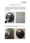
Welch Allyn SmartLink Event Pro
Copyright © 1995-2004 Welch Allyn, Inc. All rights reserved.
Part #990175 Rev. E
Overview............................................................................................................................. 3
System Requirements........................................................................................................... 4
Entering Your SmartLink Activation Code................................................................................ 5
Configuring Station Information............................................................................................. 5
Menu and Toolbar Items....................................................................................................... 5
The SmartLink Status Bar ..................................................................................................... 6
Configuring Transmission Settings ......................................................................................... 6
Receiving a Transmission...................................................................................................... 7
The Event Summary Pane..................................................................................................... 7
The Event Data Pane............................................................................................................ 8
Incident Nodes ................................................................................................................. 8
Simple ECG Waveform Data Nodes..................................................................................... 8
Shock Nodes .................................................................................................................... 8
Saving Downloaded Log File Data.......................................................................................... 9
e-mailing SmartLink Data Files .............................................................................................. 9
Entering Report Data............................................................................................................ 9
Printing Reports ................................................................................................................... 9
AED10 Infrared Communication Kit...................................................................................... 11
Welch Allyn AED20 PC Data Transfer/Serial Communication Kit .............................................. 12
Part #990175 Rev. E
2
Overview
Welch Allyn SmartLink Event Pro is a software application used to download the internal log of a
Welch Allyn AED 10 or AED 20 to a Windows-based PC for on-screen review. A variety of
information is available for review from SmartLink, including per-incident event details,
presenting rhythms, pre- and post-shock ECG waveform data, and more.
Downloading log data is fast and easy with SmartLink – a few button presses of the Welch Allyn
AED 10 or AED 20 starts data transmission. SmartLink automatically responds and downloads
data from your Welch Allyn device effortlessly. Once transmission is complete, the respective
data can be reviewed on-screen in an intuitive, easy-to-use interface. SmartLink can save
individual incidents from the log as separate files and can even e-mail SmartLink Data Files for
you, all with the click of the mouse.
The following sections will highlight the major functional areas of SmartLink, so you can be up
and running in no time.
Part #990175 Rev. E
3
System Requirements
Minimum Requirements
•
•
•
•
•
•
•
•
•
•
•
Microsoft Windows 98 SE, Me, NT 4.0 SP6, 2000, or XP
Intel Pentium II 200 MHz processor
CD-ROM drive
64 MB RAM
20 MB free Hard Disk space (more required for downloaded log data files)
SVGA-capable monitor and video card running in 1024x768 resolution, 256 color mode
Two-button mouse, or compatible pointing device
Available RS-232 serial port (required for downloading log data)
Welch Allyn IR Communication Kit (required for downloading AED 10 log data)
Welch Allyn Serial Communication Kit (required for downloading AED 20 log data)
MAPI-compliant e-mail software, such as Microsoft Outlook or Microsoft Outlook Express
Recommended Configuration
•
•
•
•
•
•
•
•
•
•
Microsoft Windows 2000 or XP
Intel Pentium III 600 MHz processor or better
CD-ROM drive
128 MB RAM
100 MB free Hard Disk space
SVGA-capable monitor and video card running in 1024x768 resolution, 64K color mode
Two-button mouse, or compatible pointing device
Available RS-232 serial port
Welch Allyn IR and Serial Communication Kits
MAPI-compliant e-mail software, such as Microsoft Outlook
If you need to
representative
Communication
Communication
order a Welch Allyn Communication Kit, please contact your Welch Allyn sales
or Welch Allyn customer service for assistance.
The Welch Allyn IR
Kit for the Welch Allyn AED 10 is part #002143, and the Welch Allyn Serial
Kit for the Welch Allyn AED 20 is part #002120.
Part #990175 Rev. E
4
Entering Your SmartLink Activation Code
The first time you run the SmartLink software, you will be required to perform two steps. The
first of these steps is to activate the software. When the Activation Code window appears, enter
the SmartLink activation code provided to you. Your activation code can be located on the
SmartLink CD-ROM jewel case or on the sleeve. If the activation code you enter is incorrect, you
will be prompted to re-enter the correct activation code.
Once you provide your SmartLink activation code, you will not have to provide this information
again unless SmartLink is installed onto another licensed machine.
Configuring Station Information
The second step that must be performed after installing the SmartLink software is configuration
of your station information. Once you enter your station information, you will not be required to
do so again. If needed, however, station information data can be updated by selecting the
Options | Configure Station Settings… menu option from within SmartLink.
Menu and Toolbar Items
SmartLink consists of three main menu items and five toolbar buttons. The menu item structure
is outlined below.
File
…
…
…
…
…
Open SmartLink File
Save SmartLink File
e-mail Current File
Print
Exit
Options
… Configure Transmission Settings
… Configure Station Settings
Help
… About
Opens a SmartLink Data File for review
Saves one or more selected incidents
e-mails the current file to selected recipient(s)
Allows printing of one or more report(s)
Exits SmartLink
Used to configure serial port settings,
transmission options, and e-mail settings
Used to enter station demographic information
Displays the SmartLink splash screen and
version information
The five toolbar buttons below the main menu correspond to the Open, Save, e-mail, Print, and
Configure menu items, respectively.
Part #990175 Rev. E
5
The SmartLink Status Bar
The SmartLink status bar displays important information about the state of the serial port
connection between the PC and your Welch Allyn device. The leftmost panel of the status bar
displays the selected serial (COM) port to be used by SmartLink. The serial port used by
SmartLink defaults to COM1, but can be changed using the Configure Transmission Settings
option (explained later in this manual). The next panel displays the baud (BPS) rate to use for
transmission of log data. The baud rate used by SmartLink defaults to 57,600 BPS and like the
serial port, may be changed if desired.
The rightmost pane indicates whether or not SmartLink is ready to receive log data transmissions
from the AED. In the event that you have selected a serial port which is unavailable, or in the
event of line conditions causing a previous transmission to fail, this rightmost pane will indicate
that SmartLink is not currently able to download data from your Welch Allyn device. When this
occurs, the Configure Transmission Settings option can be used to correct the problem.
Configuring Transmission Settings
The Configure Transmission Settings option is used to configure several SmartLink features – the
serial port and baud rate, the default folder in which to save downloaded log data, and a default
e-mail recipient.
After installation, the default SmartLink settings are as follows. The default serial port is COM1,
the baud rate setting is 57,600 BPS, and the default folder in which to save downloaded log data
files is C:\Program Files\Welch Allyn\SmartLink 3.0\Serial Transfer (this setting may vary based
on where SmartLink was installed).
From the COM/Serial Port dropbox, an available COM port may be selected. The Baud/BPS Rate
drop box provides the option of selecting 1200, 2400, 4800, 9600, 19200, 38400, or 57600 BPS.
The higher the baud rate setting, the faster transmission of log data from the AED 20 will occur,
so there is usually no reason to change the default baud rate setting of 57,600 BPS.
The Save SmartLink Transmission Files to field specifies where downloaded AED log data should
be stored on the PC. By default, a \Serial Transfer folder is created (in the folder into which
SmartLink was installed), and log data is saved in that folder. If you wish to specify a new
location, click the Browse button to select a new location. If you specify a folder which does not
exist, SmartLink will create it for you.
The Default SmartLink Transmission e-mail Recipient field allows you to specify a default
recipient to include when e-mailing SmartLink Data Files (discussed later).
Part #990175 Rev. E
6
Receiving a Transmission
When a log transmission is started by a Welch Allyn AED 10 or AED 20 connected to SmartLink, a
SmartLink Transmission in Progress window will appear. The status bar displays the number of
bytes which have been received by SmartLink. Once the transmission is complete, this window
will be closed, and the downloaded log data file will open for review automatically.
The following sections detail the various elements of the SmartLink interface used to review AED
log data.
The Event Summary Pane
When a SmartLink Data File is opened or when a transmission from your Welch Allyn device is
complete, the Incidents tab of the Event Summary Pane will be selected. The Incidents tab
displays a hierarchical listing of individual incidents, as well as the corresponding event and ECG
waveform data.
The topmost node indicates the name of the SmartLink Data File being received. SmartLink
assigns a time-unique filename to transmissions by default; however, using the Save… option
(discussed later), the file can be renamed.
Each node prefixed with a patient face icon corresponds to an incident. Each incident is a
collection of one or more events. Individual incidents may be saved using the Save… option, as
well. Clicking on an incident node will display associated incident information in the Event Data
Pane (discussed later).
Nodes prefixed with a ? icon are simple event nodes. This means that they have no other data
associated with them, other than the timestamp and event description provided.
Nodes prefixed with a shock/bolt icon are shock event nodes. Every shock node will have exactly
two child nodes below it – a pre-shock and a post-shock node. Clicking on any one of these
three nodes will display associated ECG waveform data in the Event Data Pane.
Nodes prefixed with a wave/NSR are simple ECG waveform data nodes. Clicking on a simple
waveform data node will display the associated presenting rhythm ECG waveform data in the
Event Data Pane.
The Event Summary Pane also contains a Self Test Results tab. This tab displays a list of all
routine weekly and monthly self tests performed by the Welch Allyn AED. Double clicking on an
entry in the Self Test Results list will automatically navigate you to the incident in which the
selected self test occurred.
Finally, the ++ and - - icons of the Event Summary Pane can be used to fully expand and fully
collapse the Incidents list, respectively. The
icon is used to collapse/expand the event
summary pane to allow for larger viewing area when entering patient information into forms,
previewing ECG data, etc.
Part #990175 Rev. E
7
The Event Data Pane
As discussed earlier, clicking on various nodes in the Incidents list will display information related
to that node/event. Examples of the data displayed by clicking on the various types of nodes are
shown in the following sections. Please note that only incident nodes, simple ECG waveform data
nodes, and shock nodes display associated data in the Event Data Pane. Simple event nodes
display no associated data and when clicked, the Event Data Pane informs you of this.
Incident Nodes
Contains information relative to a given incident, including the System On time, total number of
events, number of shocks delivered, serial number and software version of the Welch Allyn
device used to transfer the log data, etc.
Simple ECG Waveform Data Nodes
Displays a four (4) second strip of ECG waveform data. Also displays information such as event
date and time, heart rate, selected and delivered energy, and paddle type.
Shock Nodes
As discussed earlier, each shock node has exactly two child nodes – a pre-shock and a postshock node.
The ECG waveform data displayed depends on the node selected. If the primary/parent shock
node is selected, a full twelve (12) seconds of ECG waveform data will be displayed (four seconds
of pre-shock ECG data, and eight seconds of post-shock ECG data). A vertical blue marker is
displayed at the four-second mark to delineate the pre- and post-shock ECG data. Two textual
labels, “Pre-Shock” and “Post-Shock” are also displayed.
If either of the two child nodes are selected, only the four seconds of pre-shock ECG data or the
eight seconds of post-shock ECG data will be displayed (depending on the node selected). In this
case, no vertical marker is displayed, and only a single textual label is displayed, indicating either
“Pre-Shock” or “Post-Shock”.
Part #990175 Rev. E
8
Saving Downloaded Log File Data
After log data is transferred from your Welch Allyn device into SmartLink, the log data is saved
with a time-unique filename by default and then displayed on-screen. Using the Save SmartLink
File… option, you can select one or more incidents to save into a new file. Note that SmartLink
Data Files have a .sml extension by default.
Selecting the Save option will display a Select Incidents to Save window. Listed within this
window is each incident within the currently-opened SmartLink file. By default, the currently
selected incident is checked, allowing you to quickly save that single incident into a new
SmartLink file. You may, however, check or uncheck as many of the incidents as you would like
by clicking the box to the left of each incident.
Once the desired incidents are checked, click the Save button to specify the filename and location
of the new SmartLink file. Note that at least once incident must be selected to save a SmartLink
file.
When prompted, simply enter a new name for the file, and click Save. If you provide a file name
which already exists, you will be first prompted to confirm that you wish to overwrite the existing
file. Once complete, the new .sml file you specified is created containing only the selected
incidents and their corresponding events and is automatically opened by SmartLink.
e-mailing SmartLink Data Files
Using the e-mail Current File option in SmartLink, you can quickly and easily e-mail a SmartLink
Data File to one or more recipients. When the e-mail option is selected SmartLink will launch
your e-mail client (such as Microsoft Outlook). If you are prompted for an e-mail login name and
password when you normally use your e-mail client, simply login as usual.
SmartLink will compose a new e-mail message. The SmartLink file currently open will be added
to the message as an attachment, and a short message body will be inserted.
If you entered a default e-mail recipient using the Configure Transmission Settings option
discussed earlier, the e-mail address you provided will be inserted as the recipient. At this point,
you are free to add any additional recipients, attachments, or message body text that you would
like. When you are ready, simply click Send button, as done normally, and your e-mail message
will be sent.
Entering Report Data
When an Incident node is selected, several tabs are available, into which a number of patient
information and treatment data can be entered.
Two report forms are available for data entry: the Defibrillation Report and the EMT-D Narrative
report. When a SmartLink SML data file is saved, any data entered into either of the two
available report forms will be saved into the SML file.
Printing Reports
Part #990175 Rev. E
9
When the Print option is selected from either the SmartLink menu or the main toolbar, a dialog
box is presented, allowing the user to choose from four available report styles.
By checking the boxes of the desired report types, any or all of the desired reports can be
printed. By default, printing reports is on a per-incident basis, meaning that all reports printed
correspond to the currently selected incident within the Incidents List. If the Print selected
report for ALL incidents option is checked, however, the selected report types will be printed
for each incident within the log file.
After clicking Print, a progress window will appear indicating the status of the print job.
Part #990175 Rev. E
10
AED10 Infrared Communication Kit
Included in this kit:
TSC Electronics Infrared Adapter – part number: 900427
Hardware Installation: See figure 1
Connect the nine-pin serial connector to
the serial port on your computer.
Figure 1
**NOTE: The IR PC adapter works with SmartLink
software – part numbers 001962 and 001969. See below
for software installation instructions.
Software Installation
Infrared
To install SmartLink, insert the SmartLink CD into your
adapter
CD-ROM drive. In most cases, the software installation
should start automatically. If the installation process does not automatically start, run the
setup.exe program which can be found on the SmartLink CD. During the installation process, a
number of dialogs will be presented, asking for information such as installation location,
destination program group, etc. Unless you have a specific reason to do so, most of the default
settings do not need to be changed.
When the installation process is complete, SmartLink can be launched by either checking the
"Launch the program" checkbox from within the installer or by clicking the SmartLink icon from
within the Welch Allyn SmartLink Direct program folder. A PDF version of the SmartLink manual
can also be found in the SmartLink program folder.
If you encounter any difficulties during the installation process, contact your system administrator
for assistance. SmartLink Direct requires Windows 98SE or better to operate correctly.
How to use your IrDA PC Adapter: See figure 2
With the SmartLink program open, position the infrared adapter so that it is 3 –
12” away from the AED10 and facing the infrared data port.
1. Turn on the AED10 and enter the logsetup menu.
2. Select “SmartLink” and press enter.
NOTE: Once SmartLink is selected it will
3 – 12 “
become the default setting, and steps 2 & 3 can
be skipped.
3. From the log menu, select “Send to PC” and
Figure 2
press enter.
4. “Send to PC” will flash on the AED10 and SmartLink will indicate a transmission status as
data from the log is being transmitted to the PC.
Technical Support Contact Information:
For assistance, please consult your AED10 User’s Manual or your SmartLink User’s Manual. If you have any additional
questions please contact Welch Allyn at:
Welch Allyn, Inc.
1000 Asbury Dr.
Buffalo Grove, IL 60089
USA
(847) 520-0300
www.welchallyn.com
Part #990175 Rev. E
11
Infrared
data port
Welch Allyn AED20 PC Data Transfer/Serial Communication
Kit
002120
Part Numbers in this kit:
520468
PC Data Transfer Adapter (Figure 1)
520469
Serial Printer Transfer Adapter (Figure 2)
551778
AED Serial Communication Cable (Figure 3)
Printing to a PC:
1. Connect the Serial Communication Cable (551778) into the Welch Allyn AED20 serial data
port (see figure 4) and to the PC Data Transfer Adapter (520468). Connect the PC Data
Transfer Adapter to the 9-pin serial port on your PC.
2. Start a Terminal or Serial Communications program on your PC. Set the port settings to
9600 baud, N, 8,1.
3. Turn the Welch Allyn AED20 on, select Text mode and 9600 baud from the Log>Setup
menu. Press Print. The log icon will be replaced by a printer icon
. A flashing
printer icon indicates an error. If printer icon flashes, verify that the cable and adapter
are connected correctly.
Printing to a serial printer:
1. Connect the Serial Communication Cable (551778) into the Welch Allyn AED20 serial data
port (see figure 1) and to the Serial Printer Transfer Adapter (520469). Connect the
Serial Printer Transfer Adapter to the serial printer.
2. Turn the Welch Allyn AED20 on, select the desired mode from the Log>Setup menu.
Select Text mode and 9600 baud to print the log. Press Print. The log icon will be
replaced by a printer icon
. A flashing printer icon indicates a printer error. If
printer icon flashes, verify that printer is on-line and that there is paper in the tray.
Downloading to SmartLink:
To install SmartLink, insert the SmartLink CD into your CD-ROM drive. In most cases, the
software installation should start automatically. If the installation process does not automatically
start, run the setup.exe program which can be found on the SmartLink CD. During the
installation process, a number of dialogs will be presented, asking for information such as
installation location, destination program group, etc. Unless you have a specific reason to do so,
most of the default settings do not need to be changed.
When the installation process is complete, SmartLink can be launched by either checking the
"Launch the program" checkbox from within the installer or by clicking the SmartLink icon from
within the Welch Allyn SmartLink Direct program folder. A PDF version of the SmartLink manual
can also be found in the SmartLink program folder. The log of the AED20 should be set to RS232
and the baud rate should be set to the same value as SmartLink. Connect one end of the Serial
Communication Cable (551778) to the AED20 and the other to the PC Adapter (520468). Then
connect the PC adapter to the PC. The data can then be downloaded by selecting Menu, Log,
and then Send on the AED20.
If you encounter any difficulties during the installation process, contact your system administrator
for assistance. SmartLink Direct requires Windows 98SE or better to operate correctly.
Part #990175 Rev. E
12
Figure 1:
Figure 2:
Figure 3:
Figure 4:
Connect cable end
with bead to the
serial data port.
Part #990175 Rev. E
13