1
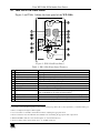
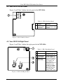
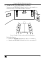
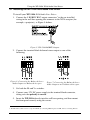
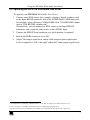
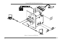
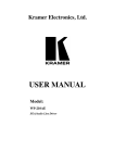
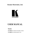
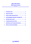
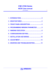
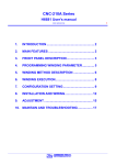
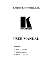
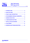
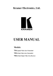
Kramer Electronics, Ltd.
USER MANUAL
Model:
WP-210A
XGA/Audio Line Driver
Contents
Contents
1
2
3
4
4.1
4.2
4.3
5
5.1
5.2
6
Introduction
Getting Started
Overview
Your WP-210A XGA/Audio Line Driver
Your WP-210A Front Panel
Your WP-210A Left Panel
Your WP-210A Right Panel
Using the WP-210A XGA/Audio Line Driver
Installing the WP-210A XGA/Audio Line Driver
Operating the WP-210A XGA/Audio Line Driver
Technical Specifications
1
1
1
2
3
4
4
5
6
7
9
Figures
Figure 1: WP-210A Front Panel
Figure 2: WP-210A Left Panel
Figure 3: WP-210A Right Panel
Figure 4: Example of Conference Room WP-210A Installation
Figure 5: WP-210A RGBHV Outputs
Figure 6: Connecting the Balanced Stereo Audio Output to a Balanced Acceptor
Figure 7: Connecting the Balanced Stereo Audio Output to an Unbalanced Acceptor
Figure 8: Connecting the WP-210A
3
4
4
5
6
6
6
8
Tables
Table 1: WP-210A Front Panel Features
Table 2: WP-210A Left Panel
Table 3: WP-210A Right Panel
Table 4: Technical Specifications of the WP-210A XGA/Audio Line Driver
3
4
4
9
i
ADDENDUM (this data is included at the end of the Overview section)
This addendum adds the following information to the user manual:
Caution – No operator-serviceable parts inside unit.
Warning – Use only the Kramer Electronics input power
wall adapter that is provided with this unit1.
Warning – Disconnect power and unplug unit from wall
before installing or removing device or servicing unit.
1 For example: model number AD2512C, part number 2535-000251
2900-9999992
A1
ADDENDUM: WP-210, WP-210E, WP-210A, WP-210AE, WP-210AL, WP-220,
WP-220E, and WP-230.
This addendum clarifies the correct color of the V sync and H sync coax cables.
The color of the coax cables with all Kramer Wall Plates, including the
WP-210, WP-210E, WP-210A, WP-210AE, WP-210AL, WP-220,
WP-220E, WP-230 will be as follows:
For V sync (vertical sync) – black1
For H sync (horizontal sync) – yellow2
1 No longer yellow
2 No longer white
P/N: 2900 - 0010431
A1
Introduction
1
Introduction
Welcome to Kramer Electronics (since 1981): a world of unique, creative and
affordable solutions to the infinite range of problems that confront the video,
audio and presentation professional on a daily basis. In recent years, we have
redesigned and upgraded most of our line, making the best even better! Our
500-plus different models now appear in 8 Groups1, which are clearly defined
by function.
Congratulations on purchasing your WP-210A XGA/Audio Line Driver active
wall plate2, which is ideal for graphics and audio installations in board,
conference and training rooms, as well as long distance signal distribution.
The package includes the following items:
WP-210A XGA/Audio Line Driver
This user manual3
2
Getting Started
We recommend that you:
Unpack the equipment carefully and save the original box and packaging
materials for possible future shipment
Review the contents of this user manual
Use Kramer high performance high resolution cables4
3
Overview
The Kramer WP-210A XGA/Audio Line Driver—part of our successful line
of Wall Plate Adapters—is an enhanced version of our popular WP-210 XGA
Line Driver wall plate.
The WP-210A XGA/Audio Line Driver includes:
A VGA input (up to UXGA resolution) on a standard HD-15 connector
Local monitor loop-through on an HD15F connector
1 GROUP 1: Distribution Amplifiers; GROUP 2: Video and Audio Switchers, Matrix Switchers and Controllers; GROUP 3:
Video, Audio, VGA/XGA Processors; GROUP 4: Interfaces and Sync Processors; GROUP 5: Twisted Pair Interfaces;
GROUP 6: Accessories and Rack Adapters; GROUP 7: Scan Converters and Scalers; and GROUP 8: Cables and Connectors
2 In addition to our active wall plate devices, Kramer’s WP series consists of passive wall plate and passive connection
modules that work with the WP Frame and/or the VPM-2 XGA Line Driver wall plate
3 Download up-to-date Kramer user manuals from the Internet at this URL: http://www.kramerelectronics.com
4 The complete list of Kramer cables is on our Web site at http://www.kramerelectronics.com
1
Your WP-210A XGA/Audio Line Driver
An amplified and equalized RGBHV output on 5 BNC connectors
An unbalanced stereo audio input on a 3.5mm mini jack
A balanced stereo audio output on a terminal block connector
In particular, the WP-210A XGA/Audio Line Driver has:
Level1 control
Cable equalization control
Left and right audio level controls
Buttons for ID Bit control and loop termination
Switches to select between analog / digital sync operation
Resolution exceeding UXGA, that ensures transparent operation
A standard 12 Volt DC feed
Achieving the best performance means:
Connecting only good quality connection cables, thus avoiding
interference, deterioration in signal quality due to poor matching, and elevated
noise levels (often associated with low quality cables)
Avoiding interference from neighboring electrical appliances
Positioning your WP-210A away from moisture, excessive sunlight and dust
4
Your WP-210A XGA/Audio Line Driver
This section defines the WP-210A XGA/Audio Line Driver:
Front panel (see section 4.1)
Left panel (see section 4.2)
Right panel (see section 4.3)
1 VGA/UXGA output signal
2
KRAMER: SIMPLE CREATIVE TECHNOLOGY
Your WP-210A XGA/Audio Line Driver
4.1 Your WP-210A Front Panel
Figure 1 and Table 1 define the front panel of the WP-210A:
Figure 1: WP-210A Front Panel
Table 1: WP-210A Front Panel Features
#
1
2
3
4
5
6
7
8
9
Feature
Input HD15F Connector
EQ.1 Potentiometer
Level Potentiometer
AUDIO R Level Trimmer
AUDIO L Level Trimmer
AUDIO Input 3.5mm Mini Jack
Holes (2)
ON LED
ID Bit Button
10 Term. Button
11 VGA Det. LED
12 Loop HD15F Connector
Function
Connect to the VGA/XGA source
Adjusts2 the cable compensation equalization level
Adjusts2 the output signal level
Adjusts3 the right audio output signal level
Adjusts3 the left audio output signal level
Connects to the unbalanced stereo audio source
For fastening the wall plate in place
Illuminates when receiving power
Selects ID BIT when pushed in (when outputting a VGA signal
from a notebook to an external VGA monitor4)
Terminates with 75 when pushed in, or release for looping
Illuminates when detecting an XGA5 signal
For VGA/XGA looping to increase output availability
1 Degradation and VGA/XGA signal loss can result from using long cables (due to stray capacitance), sometimes leading to a
total loss of sharpness in high-resolution signals
2 Use a screwdriver to carefully rotate the Potentiometer, adjusting the appropriate level
3 Insert a screwdriver into the small hole and carefully rotate it, trimming the appropriate audio output level
4 When the ID BIT is ON, the notebook will output to an external VGA monitor
5 At any resolution (VGA, SVGA, XGA and so on, and HD resolutions)
3
Your WP-210A XGA/Audio Line Driver
4.2 Your WP-210A Left Panel
Figure 2 and Table 2 define the left panel of the WP-210A:
Table 2: WP-210A Left Panel
#
1
Feature
Bal. Audio Out
Terminal Block
Connector
Function
Connects to the
balanced stereo audio
acceptor
Figure 2: WP-210A Left Panel
4.3 Your WP-210A Right Panel
Figure 3 and Table 3 define the right panel of the WP-210A:
Table 3: WP-210A Right Panel
#
Feature
Function
1
+12V GND
+12V DC connector
for powering the unit
2
H (Horizontal)
Sync Switch
3
V (Vertical)
Sync Switch
Set both switches to
TTL for a digital sync
source (for example, a
graphics card from a
PC or laptop). Set
both switches to
Analog if the source is
analog based, for
example, an RGBHV
source with coaxial
cable for sync, such
as a camera with
analog H and V syncs
Figure 3: WP-210A Right Panel
4
KRAMER: SIMPLE CREATIVE TECHNOLOGY
Using the WP-210A XGA/Audio Line Driver
5
Using the WP-210A XGA/Audio Line Driver
You can use your WP-210A XGA/Audio Line Driver, for example, in a
conference room, as the example in Figure 4 illustrates:
Figure 4: Example of Conference Room WP-210A Installation
For details of how to:
Install your WP-210A XGA/Audio Line Driver, see section 5.1
Operate your WP-210A XGA/Audio Line Driver, see section 5.2
5
Using the WP-210A XGA/Audio Line Driver
5.1 Installing the WP-210A XGA/Audio Line Driver
To install your WP-210A XGA/Audio Line Driver:
1. Connect the 5 RGBHV BNC output connectors1 to the pre-installed
wiring in the wall box opening that connects to the XGA acceptor (for
example, a projector), as Figure 5 defines.
Figure 5: WP-210A RGBHV Outputs
2. Connect the terminal block balanced stereo output as one of the
following:
Figure 6: Connecting the Balanced Stereo
Audio Output to a Balanced Acceptor
Figure 7: Connecting the Balanced Stereo
Audio Output to an Unbalanced Acceptor
3. Set both the Hs and Vs switches.
4. Connect your 12V DC power supply to the terminal block connector,
taking care that polarity is correct.
5. Insert the WP-210A directly into the wall box opening, and then mount
the front panel securely using the screws.
1 The WP-210A could be used for component HDTV by connecting YPbPr in place of GBR, and not connecting H and V
6
KRAMER: SIMPLE CREATIVE TECHNOLOGY
Using the WP-210A XGA/Audio Line Driver
5.2 Operating the WP-210A XGA/Audio Line Driver
To operate your WP-210A XGA/Audio Line Driver:
1. Connect your XGA source (for example, a laptop’s digital graphics card)
to the Input HD15F connector and to the AUDIO Input 3.5mm mini jack,
for example, using a Kramer C-GMA/GMA cable (VGA HD15M +Audio
jack to VGA HD15M +Audio jack)1.
Alternatively, you can connect an XGA source to the Input HD15F
connector, and a separate audio source to the AUDIO Input.
2. Connect the HD15F Loop connector to a local monitor, if required.
3. Push in the ID Bit button to set to ON.
4. Adjust2 the output signal level and/or cable compensation equalization
level, if required, as well as the right3 and/or left3 audio output signal levels.
1 Not supplied. The complete list of Kramer cables is on our Web site at http://www.kramerelectronics.com
2 Use a screwdriver to carefully rotate the Potentiometer, adjusting the appropriate level
3 Insert a screwdriver into the small hole and carefully rotate it, trimming the appropriate audio output level
7
Using the WP-210A XGA/Audio Line Driver
Figure 8: Connecting the WP-210A
8
KRAMER: SIMPLE CREATIVE TECHNOLOGY
Technical Specifications
6
Technical Specifications
Table 4 includes the technical specifications:
1
Table 4: Technical Specifications of the WP-210A XGA/Audio Line Driver
INPUTS:
VIDEO: Looping analog red, green,
AUDIO: Unbalanced stereo 3.5mm
mini jack
blue signals: 0.7 Vpp/75 , H and V
sync, TTL level, on HD15F connectors
OUTPUTS:
VIDEO: 1 RGBHV on 5 BNC
AUDIO: Balanced stereo terminal
connectors
block connector
MAX. OUTPUT LEVEL: VIDEO: 2Vpp
AUDIO: 5.3Vpp
RESOLUTION:
Exceeding UXGA
DIFF. GAIN:
0.05%
DIFF. PHASE:
0.02 Deg.
K-FACTOR:
<0.05%
S/N RATIO:
VIDEO: 74.2dB
CONTROLS:
Cable EQ. control: 0dB to +8dB @ 50 MHz; Level control: -1.3dB to +6dB
ID BIT button; TERM button; Hs (Horizontal) and Vs (Vertical) Sync switches;
right and left audio level controls
COUPLING:
VIDEO: AC
AUDIO: AC
AUDIO BANDWIDTH:
>100kHz
AUDIO THD + NOISE:
<0.032%
AUDIO 2nd HARMONIC: <0.005%
POWER SOURCE:
12 VDC, 95mA
DIMENSIONS:
6.9cm x 5.0cm x 11.4cm (2.72" x 1.97" x 4.49", W, D, H)
WEIGHT:
0.3 kg (0.67 lbs.) approx
ACCESSORIES:
Power supply
1 Specifications are subject to change without notice
9
LIMITED WARRANTY
Kramer Electronics (hereafter Kramer) warrants this product free from defects in material and workmanship under the
following terms.
HOW LONG IS THE WARRANTY
Labor and parts are warranted for seven years from the date of the first customer purchase.
WHO IS PROTECTED?
Only the first purchase customer may enforce this warranty.
WHAT IS COVERED AND WHAT IS NOT COVERED
Except as below, this warranty covers all defects in material or workmanship in this product. The following are not covered
by the warranty:
1.
2.
3.
Any product which is not distributed by Kramer, or which is not purchased from an authorized Kramer dealer. If you are
uncertain as to whether a dealer is authorized, please contact Kramer at one of the agents listed in the web site
www.kramerelectronics.com.
Any product, on which the serial number has been defaced, modified or removed.
Damage, deterioration or malfunction resulting from:
i)
Accident, misuse, abuse, neglect, fire, water, lightning or other acts of nature
ii)
Product modification, or failure to follow instructions supplied with the product
iii)
Repair or attempted repair by anyone not authorized by Kramer
iv)
Any shipment of the product (claims must be presented to the carrier)
v)
Removal or installation of the product
vi)
Any other cause, which does not relate to a product defect
vii)
Cartons, equipment enclosures, cables or accessories used in conjunction with the product
WHAT WE WILL PAY FOR AND WHAT WE WILL NOT PAY FOR
We will pay labor and material expenses for covered items. We will not pay for the following:
1.
2.
3.
Removal or installations charges.
Costs of initial technical adjustments (set-up), including adjustment of user controls or programming. These costs are the
responsibility of the Kramer dealer from whom the product was purchased.
Shipping charges.
HOW YOU CAN GET WARRANTY SERVICE
1.
2.
3.
To obtain service on you product, you must take or ship it prepaid to any authorized Kramer service center.
Whenever warranty service is required, the original dated invoice (or a copy) must be presented as proof of warranty coverage,
and should be included in any shipment of the product. Please also include in any mailing a contact name, company, address, and
a description of the problem(s).
For the name of the nearest Kramer authorized service center, consult your authorized dealer.
LIMITATION OF IMPLIED WARRANTIES
All implied warranties, including warranties of merchantability and fitness for a particular purpose, are limited in duration to
the length of this warranty.
EXCLUSION OF DAMAGES
The liability of Kramer for any effective products is limited to the repair or replacement of the product at our option. Kramer
shall not be liable for:
1.
2.
Damage to other property caused by defects in this product, damages based upon inconvenience, loss of use of the product, loss
of time, commercial loss; or:
Any other damages, whether incidental, consequential or otherwise. Some countries may not allow limitations on how long an
implied warranty lasts and/or do not allow the exclusion or limitation of incidental or consequential damages, so the above
limitations and exclusions may not apply to you.
This warranty gives you specific legal rights, and you may also have other rights, which vary from place to place.
NOTE: All products returned to Kramer for service must have prior approval. This may be obtained from your dealer.
This equipment has been tested to determine compliance with the requirements of:
EN-50081:
"Electromagnetic compatibility (EMC);
generic emission standard.
Part 1: Residential, commercial and light industry"
EN-50082:
"Electromagnetic compatibility (EMC) generic immunity standard.
Part 1: Residential, commercial and light industry environment".
CFR-47:
FCC Rules and Regulations:
Part 15: “Radio frequency devices
Subpart B – Unintentional radiators”
CAUTION!
Servicing the machines can only be done by an authorized Kramer technician. Any user who makes changes or modifications to
the unit without the expressed approval of the manufacturer will void user authority to operate the equipment.
Use the supplied DC power supply to feed power to the machine.
Please use recommended interconnection cables to connect the machine to other components.
10
KRAMER: SIMPLE CREATIVE TECHNOLOGY
For the latest information on our products and a list of Kramer
distributors, visit our Web site: www.kramerelectronics.com,
where updates to this user manual may be found.
We welcome your questions, comments and feedback.
Safety Warning:
Disconnect the unit from the power supply before
opening/servicing.
Caution
Kramer Electronics, Ltd.
Web site: www.kramerelectronics.com
E-mail: [email protected]
P/N: 2900-000210 REV 2