1
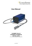
User Manual
KLEIBER 740
INFRARED PYROMETER
for non-contact temperature measurement
Issue 10/2008
Address/Copyright
LumaSense Technologies GmbH
Kley erstr. 90
D - 60326 Frankfurt
Germany
Phone:
Fax:
E-Mail:
Internet:
+49-69-97373-0
+49-69-97373-167
[email protected]
www.Lumasenseinc.com
© 2007 IMPAC Sensor GmbH is a subsidiary company of IMPAC group.
Any reproduction of this user manual or part thereof, its storage on electronic media
and translation of the manual into foreign languages without written approval of the
company LumaSense Technologies GmbH is strictly forbidden.
Table of Contents
Table of Contents
Table of Contents ......................................................................................................................... 3
Table of Illustrations...................................................................................................................... 4
1
Basic Information .................................................................................................................. 1
1.1
Notes for the User Manual ............................................................................................ 1
1.2
Purpose......................................................................................................................... 1
1.3
Intended Use................................................................................................................. 2
1.4
Warranty and Liability ................................................................................................... 2
1.5
Scope of Delivery.......................................................................................................... 3
2
Technical Data ...................................................................................................................... 4
3
Safety.................................................................................................................................... 6
3.1
Symbols and Signal Words Used ................................................................................. 6
3.2
General Safety Notes.................................................................................................... 7
4
Technical Description ........................................................................................................... 8
4.1
System Design/Principle of Operation .......................................................................... 8
4.1.1 Optics ........................................................................................................................ 8
4.1.2 Operating and display elements.............................................................................. 10
4.1.3 Connections and interfaces..................................................................................... 10
5
Transport and Storage ........................................................................................................ 13
5.1
Transport of the pyrometer ......................................................................................... 13
5.2
Storage of the pyrometer ............................................................................................ 14
6
Starting Up .......................................................................................................................... 15
6.1
Installation Site Requirements .................................................................................... 15
6.2
Installation................................................................................................................... 16
6.2.1 Fix and connect the pyrometer................................................................................ 16
6.2.2 Align pyrometer ....................................................................................................... 17
7
Operation of the pyrometer ................................................................................................. 18
7.1
Setting the Vario optic................................................................................................. 18
7.2
Adjusting the Parameters............................................................................................ 19
8
Troubleshooting .................................................................................................................. 20
9
Maintenance and Care ....................................................................................................... 21
9.1
General information .................................................................................................... 21
9.2
Cleaning the Optics..................................................................................................... 21
10
Accessories..................................................................................................................... 22
11
Taking out of service, Disposal ....................................................................................... 23
11.1
Taking out of service................................................................................................... 23
11.2
Disposal ...................................................................................................................... 23
KLEIBER 740
Table of Illustrations
Table of Illustrations
Fig. 1
Structure of the pyrometer .................................................................................................. 8
Fig. 2
Vario optics ......................................................................................................................... 9
Fig. 3
Macro optics measuring set-up (KS/ KG 740) .................................................................... 9
Fig. 4
Macro optics measuring set-up (KGA 740) ........................................................................ 9
Fig. 5
Operating and display elements ....................................................................................... 10
Fig. 6
Connecting plug for 5-pin connecting cable ..................................................................... 11
Fig. 7
Cooling water connections (tube screw connector ¼") .................................................... 11
Fig. 8
Pyrometer connections ..................................................................................................... 16
Fig. 9
Pyrometer wire connection with configuration .................................................................. 17
Fig. 10
Setting the vario optic................................................................................................... 18
KLEIBER 740
Basic Information
1
Basic Information
1.1
Notes for the User Manual
This user manual describes the structure of the KLEIBER 740 infrared pyrometer for noncontact temperature measurement and gives the operators all the necessary information
related to installation, operation, de-installation along with information related to
maintenance and repairs of the pyrometer. When malfunctions occur, the user manual
provides suggestions for their potential causes and their repair.
This user manual is intended for qualified service and maintenance personnel with
appropriate technical expertise including a basic knowledge of temperature measuring
technology.
Before you use the pyrometer for temperature measurement, you must have read and
understood these operating instructions! Keep the manual so that it is available at all times.
Take into account all the requirements given in this user manual. This is a pre-condition for
the correct and professional use of the pyrometer,
proper maintenance, cleaning and care of the pyrometer
prevention of risks and strict observance of the essential technical safety regulations.
Document structure and Symbols
Operating instructions to be performed in sequence are numbered in chronological order.
They are grouped together in operational units and accompanied by the corresponding
results.
Listings without a sequential order are presented as bullet points and items in sub-lists are
preceded by dashes.
Safety precautions are shown with pictograms and key words. They provide information
about the type, source and consequences of the hazard, and safety precautions. The
meanings of the pictograms and key words are explained in the "Safety Instructions"
chapter.
1.2
Purpose
The KLEIBER 740 pyrometer is particularly intended for the non-contact measurement of
surface temperatures on metal, ceramic, plastics and is specially designed for industrial
applications as well as applications in the area of research and development.
The 740 also enables you to solve high speed applications in laser areas by using laser
rejection filters and challenging temperature measurement on silicon or tungsten.
KLEIBER 740
1
Basic Information
1.3
Intended Use
The KLEIBER 740 pyrometer is to be used exclusively for the non-contact measurement of
surface temperatures of the materials specified in section 1.2. Any applications beyond that
area are not allowed! Any damage resulting from this is the sole responsibility of the
operator.
Proper use of the plant also includes:
the observance of the requirements of these operating instructions for transport and
storage, assembly, operation and care of the pyrometer
the observance of the power requirements specified in section 2 and the operating
and environmental conditions
the compliance with the legal accident prevention and environmental regulations
Among applications/conditions for which the pyrometer is not intended for use are in
particular:
the use of the pyrometer within medical areas
the use of the pyrometer in the food industry
the use of the pyrometer in areas where there is danger of explosion
the use of the pyrometer outside of the operating and environmental conditions
specified in section 2
1.4
Warranty and Liability
The LumaSense Sensor GmbH offers a warranty of 2 years for the pyrometer starting from
the date of billing. The warranty covers manufacturing defects as well as defects which are
determined during operation and which can be imputed to defects of LumaSense Sensor
GmbH. In these cases, the pyrometer will be repaired free of charge. The freight charges
are the responsibility of the respective sender.
LumaSense Sensor GmbH reserves the right to exchange the equipment or parts of the
instrument instead of a repair. After a repair, LumaSense Sensor GmbH offers a warranty of
12 months on all repaired and/or exchanged instrument components.
Deviations from the proper use described in this user manual will result in restricted
warranty and liability or the loss in case of damage. Damage to wearing parts
(e.g. fuses) is excluded from the guarantee.
Warranty and liability claims for personal injuries and/or material damage are excluded if
this or these result from one or more of the following causes:
Improper use of the pyrometer
inappropriate operation and servicing of the pyrometer
unauthorized modifications to the pyrometer without prior consultation with LumaSense
Sensor GmbH
rough, mechanical actions or deliberate destruction of the pyrometer
2
KLEIBER 740
Basic Information
Connection error (overvoltage)
Frost damage by not observing the permitted environmental conditions and/or by
inappropriate storage
Malfunctions that are caused by non-conformance to this user manual
1.5
Scope of Delivery
The scope of delivery of the pyrometer includes:
High speed infrared pyrometer KLEIBER 740
(KS 740 or KG 740 or KGA 740)
Vario optics (optional macro optics)
retaining pin ∅ 14.9 mm, length 100 mm
water cooling connection
inspection sheet
user manual
IMPORTANT
The connecting cable is not included in scope of delivery. Please order it according to the
length required.
KLEIBER 740
3
Technical Data
2
Technical Data
Manufacturer's data
Manufacturer
LumaSense Sensor GmbH
Name of the pyrometer
KLEIBER 740
Design data
Length (basic instrument)
170 mm
Width
170 mm
Height
70 mm
Length with maximum extension of optics:
with straight connector
with angled connector
320 mm
300 mm
Weight
approx. 1.2 kg
Characteristic data
Measurement range in °C/ Spectral range in
µm
4
KS 740
[600 … 1.600] °C
[800 … 2.300] °C
[0.85 … 1.05] μm
[0.85 … 1.05] μm
KG 740
[300 … 1.400] °C
[800 … 2.500] °C
[1.58 … 1.80] μm
[1.58 … 1.80] μm
KGA 740
[160 … 1.000] °C
[300 … 2.300] °C
[1.58 … 2.20] μm
[2.00 … 2.20] μm
Measurement outlet
analogue
[0 … 20] mA or [4 … 20] mA,
maximum burden 500 Ω, galvanically separated
Accuracy:
0.75 % of measured value (at 25°C, ε=1)
Reproducibility:
< 0,3 % of measured value (at 25°C, ε=1)
Response time t95
6 µs via voltage output
9 µs via current output
Emissivity (ε)
adjustable from 0.1…1
Vario optic (standard)
for measuring distances and measuring fields
please refer to table next below
Macro optic (optional)
measuring distance: 288 mm (KS 740 and KG 740)
290 mm (KGA 740)
measuring field: ∅ 0.7 mm (KS 740 and KG 740)
∅ 1.0 mm (KGA 740)
Sighting mechanism
LED pilot light or optional through lens sighting
Operating temperature
[0 … +40] °C
[0 … +80] °C with water cooling
KLEIBER 740
Technical Data
Storage temperature
[-20 … +70] °C
Power supply
24 V DC, 0.2 A or 24 V AC, 0.2 A
Degree of protection:
IP 54 according to DIN 40 050
Cooling
− connection
− flow rate
− pressure
− coolant temperature
tube screw connector ¼ "
at least 1 l/min
maximum 6 bar
[10 … 35] °C
Test base
EN 55 011 : 1998, limit class A
CE marking
according to EU regulations
Vario optic
a*1 in mm
450
600
800
1000
1200
1400
1600
1800
2000
2500
3000
M*2 in mm
2.5
4.0
6.0
8.0
10.5
11.5
13.0
14.0
15.0
20.0
28.0
*1 Distance from optics front edge
*2 Measuring field diameter
KLEIBER 740
5
Safety
3
Safety
3.1
Symbols and Signal Words Used
The following symbols and key words are used in the user manual to indicate hazards and
instructions. Safety precautions always appear before an action.
DANGER
Indicates a potentially dangerous situation. Failure to abide may result in light or minor
injury and damage.
CAUTION
Indicates a potentially damaging situation. Failure to abide may result in damage to the
product or to anything near the product.
IMPORTANT
Indicates useful tips and other specifically useful information that allow any dangerous or
damaging situations to be avoided.
REFERENCE TO ENVIRONMENTAL PROTECTION
Important instructions for protecting the environment
6
KLEIBER 740
Safety
3.2
General Safety Notes
The KLEIBER 740 pyrometer has been built in accordance with the currently valid standards
of the technology and the recognized safety regulations and ensures the highest safety
level.
The fundamental safety and occupational safety requirements of applicable laws, standards,
and guidelines have been taken into account in the pyrometer design. The safety of the
pyrometer is confirmed by the declaration of conformity and the CE mark.
All information related to safety is with reference to the regulations of the European Union
currently in force. In other countries, applicable laws, national directives and safety
regulations have to be met.
Apart from the safety instructions given in these operating instructions, you should also take
into account the generally valid regulations for accident prevention and environmental
protection as well as the regulations of the respective professional associations and strictly
comply with them.
Note the general safety instructions:
Commissioning of the pyrometer may only be carried out by persons qualified to do
so, taking the safety instructions into account.
Pay attention to the installation site requirements and notes for commissioning (see
section 6).
Only use the original cables provided as accessories for the connection of the
pyrometer. Other cables, especially cables manufactured by yourself, are not
permitted.
Lay all cables and cooling water pipes in such a way that they are not exposed to any
tension and are not clamped or squashed.
Before start-up, carry out a visual inspection for damage to the components of the
pyrometer (housing, optics, cable and pipes). Never operate the pyrometer with
damaged components.
KLEIBER 740
7
Technical Description
4
Technical Description
4.1
System Design/Principle of Operation
Fig. 1 shows the basic structure of the pyrometer. The basic parts of a pyrometer are the
lens, aperture, filter detector, and the signal processing unit. The infrared radiation coming
in from the object to be measured is gathered by the lens. The aperture blocks unwanted
rays at the edges. The filter permits only the desired spectral range to enter. The rays then
pass through to the detector which transforms the infrared radiation into electric signals.
These signals are then linearised in the signal processing unit and changed into a standard
output signal which can then be read in the display, and be used for process control.
The operating elements as well as the connections/interfaces are located at the back of the
pyrometer (see pages 10 to Fehler! Textmarke nicht definiert.).
The coolant connections are located under the instrument.
Fig. 1
4.1.1
Structure of the pyrometer
Optics
Depending on the application (measuring distance, measuring field diameter, etc.), the
pyrometer is equipped with a vario-optic or a macro-optic.
Vario optics
The Vario optic can be adjusted to the required measuring distance and allows small
measuring fields for various distances to the object being measured. The object being
measured can be at an arbitrary distance, but must be at least as large as the measuring
field at that distance (see section 7.1).
8
KLEIBER 740
Technical Description
Fig. 2
Vario optics
1
2
3
4
Object to be measured
Measuring field
Optical ray from vario tube
Ring nut
Macro optics
The macro-optics is a fixed optics for very small measuring fields, i.e. a certain measuring
field diameter is given for a certain measuring distance.
Fig. 3
Macro optics measuring set-up (KS/ KG 740)
Fig. 4
Macro optics measuring set-up (KGA 740)
1
2
3
4
Object to be measured
Measuring field ∅ = 0.7 mm (KS/ KGA 740), ∅ = 1.0 mm (KGA 740)
Macro tube
Pyrometer front edge
IMPORTANT
The macro tube cannot be adjusted. The distances mentioned must be respected
absolutely in order to ensure the small measuring field.
KLEIBER 740
9
Technical Description
4.1.2
Operating and display elements
The controls and indicators are located on the rear side of the device. For the meaning of
individual elements refer to legend Fig. 5, for operation of the pyrometer see section 7.
Fig. 5
4.1.3
Operating and display elements
Operating and display element
Meaning
1
Push button for pilot light
(optional through lens sighting)
switch on/ off the pilot light
2
Potentiometer [emissivity]
adjustment of emissivity from 0.1 … 1
Connections and interfaces
The 5-pole plug to connect the instrument is at the rear side of the unit (see Fig. 66). The
contacts of the 5-pole plug are arranged as follows:
Plug pin
10
Meaning
1
Supply voltage +24 V (DC or AC)
2
Supply voltage 0 V (DC or AC)
3
ground output
4
Analogue output [0 (4) … 20] mA
5
empty
KLEIBER 740
Technical Description
3
4
Fig. 6
Connecting plug for 5-pin connecting cable
Operating and display element
Meaning
3
BNC Output
BNC output 0 … 10 V for connection to
storage oscilloscope
4
5-pin plug connection
Power supply connection and output
[0(4) … 20] mA
Cooling water connection
At ambient temperatures of more than 40°C the pyrometer must be operated with the
associated cooling! The two connections for the connection of a cooling circuit are located
under the instrument (see Fig. 77).
The following should be taken into account when connecting a cooling circuit:
Flow rate
at least 1 l/min
Pressure:
maximum 6 bar
Coolant temperature
10 °C to 35 °C
Fig. 7
Cooling water connections (tube screw connector ¼")
Cold tap water is usually sufficient for cooling. It should not be so strongly cooled that
condensation develops on the instrument. Take into account the environmental conditions
(air temperature and humidity) with respect to the cooling.
KLEIBER 740
11
Technical Description
Mounting
There is a retaining pin (scope of delivery) through which the pyrometer can be fixed using
various brackets.
We recommend fixing the pyrometer using the retaining pin and optional available ball and
socket mounting support with clamp or thread. This mounting plate ensures secure
assembly of the pyrometer as well as optimal adjustment with respect to the object being
measured (for order data see page 22).
12
KLEIBER 740
Transport and Storage
5
Transport and Storage
5.1
Transport of the pyrometer
CAUTION
Environmental factors, impacts and the formation of water condensation may damage some
components!
When transporting the pyrometer, take suitable measures to protect all components from
environmental factors, impacts and the formation of water condensation! Temporary
storage of the pyrometer in the open air is not permitted!
Prepare the pyrometer for transport as follows:
1. Switch the pyrometer off so that there is no tension and remove the connecting cable
and the signal cable.
2. In case of usage of water cooling please remove the cooling water pipes from the
cooling water connectors and remove the water from the pyrometer.
3. Pivot the optics completely and lock these with the adjusting ring.
4. Protect the optics against scratches through suitable measures (e.g. protective cap,
foil, …).
5. Pack the pyrometer in the original packaging paying attention to the means of
transport (see transport instructions below).
The pyrometer is thus ready to be shipped.
It is advisable to use the original packaging for the shipping of the pyrometer. If the original
packaging is no longer available, the pyrometer should be shipped in a cardboard box with
shock-absorbing PE material.
When transporting the pyrometer observe the following instructions:
Take great care when transporting the pyrometer to avoid damage through the effect
of force, or careless loading or unloading.
Avoid jerks, vibrations and the formation of condensed water due to severe
temperature deviations while transporting.
In the case of overseas shipping, a suitable desiccator (e.g. Silicagel) should be
inserted and the pyrometer should be sealed together with the desiccator in a
protective plastic sheet.
If the pyrometer is not immediately installed after delivery and put into operation, then
it should be carefully stored in a location protected against dust and humidity (storage
conditions - see section 5.2).
KLEIBER 740
13
Transport and Storage
5.2
Storage of the pyrometer
CAUTION
Environmental factors and water condensing may damage some components!
Store the pyrometer only in dry areas without large variations in temperature! The
atmosphere should be free of dust and corrosive vapours!
CAUTION
There is a danger of destruction by using freezing cooling water with a storage temperature
<0 °C!
Before storage of the pyrometer if applicable remove any remaining cooling water from the
cooling ducts of the equipment! Storage of the pyrometer with coolant remaining in the
cooling ducts is not permitted!
Store the pyrometer appropriately in the original packaging. Put a suitable desiccant inside
the packing (e.g. silica-gel) to prevent damage by moisture. Protect the pyrometer against
dust through suitable measures.
The following climatic conditions are required in the storage room of the pyrometer:
14
temperature range:
-20 °C to +70 °C
maximum air humidity:
to 70 %
atmosphere
free of dust and corrosive vapours
KLEIBER 740
Starting Up
6
Starting Up
6.1
Installation Site Requirements
CAUTION
Measurement errors and damage to the pyrometer through
– ambient temperatures too high ,
- strong contamination of the optics due to dust, smoke, steam or other causes
– air pollution,
- electromagnetic interference sources
You must take into account the following climatic conditions and the requirements of the
place of use of the pyrometer!
Climatic conditions
The following requirements must be fulfilled with respect to the climatic conditions at the
place of use of the pyrometer:
temperature range:
0 °C to +40 °C (up to +80°C with connected cooling)
maximum air humidity:
60 % at room temperature
Atmosphere
free of dust, corrosive vapours, and fume gases
Requirements at the place of use
Take into account the following requirements at the place of use of the pyrometer:
Take care with the choice of the place of use and take into account the ergonomic and
the legal guidelines for industrial safety in order to ensure safe operation of the
pyrometer.
Set up the pyrometer on a firm, stable base. The base must be free from concussion
and vibration.
Note:
We recommend using the rail mounting plate available as an accessory for the
attachment of the pyrometer as well as a clamping attachment (see page 22).
Do not expose the system to direct sunlight or radiation from heating (e.g. radiators).
Do not set the pyrometer near strong electromagnetic fields or near electromagnetic
interference sources.
Make sure that the pilot light falls unhindered on the object being measured and that
there is nothing in the path of the rays.
KLEIBER 740
15
Starting Up
6.2
Installation
6.2.1
Fix and connect the pyrometer
DANGER
There is danger of injury and possible equipment damage by connection of cables under
power!
Never connect cables under power! Make sure that the voltage supply is switched off before
connection of the cables to the pyrometer!
IMPORTANT
Operation of the pyrometer about ambient temperatures of more than 40°C is only
permitted with water cooling! Connect the pyrometer to a suitable cooling circuit with
ordinary tap water! The use of coolants is permitted only with the agreement of the
manufacturer!
The temperature of the cooling water must lie between 10 °C and 35 °C. Condensation buildup due to the low temperature of the cooling water is to be avoided.
Install the pyrometer as follows:
1. Mount the pyrometer with the help of the retaining pin and taking into account the
conditions specified in section 6.1 for the intended place of use.
2. Connect, if necessary (only in case of ambient temperatures more than 40°C) the
water cooling (position 1, Fig. 8).
3. Connect the coloured wires of the 5-pole connecting cable (item B, Fig. 8) to
appropriate connections of a switchboard. For wire configuration please see legend
to fig. 8.
4. Connect the 5-pole connecting cable to the pyrometer at the back of the instrument
(item 2, Fig. 8) and to the power supply.
5. Double check stable set up of the pyrometer.
The pyrometer is ready for use and can be switched on.
Fig. 8
Pyrometer connections
1
2
16
Cooling circuit connections
Connect 5-pole connecting cable.
KLEIBER 740
Starting Up
Fig. 9
Pyrometer wire connection with configuration
Connector A
Pin 1
Supply voltage +24 V (DC or AC)
Pin 2
Supply voltage 0 V (DC or AC)
Pin 3
ground output
Pin 4
Analogue output [0 (4) … 20] mA
Pin 5
empty
Connector B
6.2.2
Meaning
Meaning
1 - white
Supply voltage +24 V (DC or AC)
2 - brown
Supply voltage 0 V (DC or AC)
3 - green
ground output
4 - yellow
Analogue output [0 (4) … 20] mA
5 – green-yellow
shield
Align pyrometer
The pyrometer is equipped with an LED pilot light for accurate alignment of the sensor with
the object to be measured. Align the pyrometer with the object to be measured as follows:
1. Switch on the supply voltage to the pyrometer.
2. Allow a starting time of approx. 5 minutes for thermo-stabilization. Than the pyrometer
has stabilised and is ready to work with the given accuracy.
3. Switch on the pilot light by pressing the push button at the rear side. Make sure that
there is nothing in the path of rays.
Note: In order to avoid measuring errors, the area of the pilot light must not be larger
than the object to be measured.
4. If you have a pyrometer with vario optic, adjust the necessary measuring distance (see
page 18).
Note: The macro-optics cannot be adjusted.
The pyrometer is thus aligned and ready for the temperature measurement.
KLEIBER 740
17
Operation of the pyrometer
7
Operation of the pyrometer
7.1
Setting the Vario optic
Adjust the necessary measuring distance with the help of the vario optic as follows:
1. If necessary switch on the pilot light by pressing the push button at the rear side.
2. Loosen the ring nut (item 1, Fig. 10) by turning it in a counter-clockwise direction.
3. Move the vario optic (item 2, Fig. 10) forwards and/or backwards, in order to adjust
the pyrometer to the required measuring distance.
Note:
The size of the pilot light is identical to the size of the measuring field. The measuring
field may not be larger than the object to be measured at the adjusted distance!
4. After adjusting the measuring distance, lock the annular nut by turning it in a
clockwise direction.
The vario optic is thus adjusted to the required measuring distance.
Fig. 10
Setting the vario optic
a*1 in mm
450
600
800
1000
1200
1400
1600
1800
2000
2500
3000
M*2 in mm
2.5
4.0
6.0
8.0
10.5
11.5
13.0
14.0
15.0
20.0
28.0
*1 Distance from optics front edge
*2 Spot size diameter
18
KLEIBER 740
Operation of the pyrometer
7.2
Adjusting the Parameters
Emissivity
The emissivity is the relationship between infrared energy radiated from an object and the
radiation energy of a perfect emitter (black emitter) at the same temperature and the same
spectral range.
The emissivity is material-dependent and of a considerable size in order to be able to
determine the temperature of an object accurately without contact. The emissivity of the
object being measured must therefore be known and be adjusted at the pyrometer.
Adjust the emissivity suitable for the measurement in accordance with the procedural steps
on page 19. The adjusted emission value is indicated in the main menu.
Typical emissivities for various materials are available on our homepage at
www.kleiberinfrared.com under practical knowledge or in relevant literature.
The instrument is calibrated at black body radiation (ε = 1.00). Real objects have an
emissivity less than 1.0. This difference can be stepless adjusted between 0.1 and 1.0 with
the potentiometer at the back of the instrument.
How to find out correct emissivity:
1. First measure the real temperature of measuring object with a contact thermometer
e.g. thermocouple or resistance probes. The “black” temperature (spectral
temperature) measured with a pyrometer adjusted to emissivity = 1.0 usually gives
a measuring value differing to real temperature because of the real emissivity of
<1.0. The value given by the instrument usually will be less than the real
temperature. The emission ratio of most materials depends on temperature as well
as wave length being measured.
2. You can get a correlation of the temperature scales, if you adjust the pyrometer at
the exact temperature with the help of the potentiometer of emissivity.
After adjusting the emissivity factor through a correlation measurement you can now
measure temperatures for the calibrated temperature range at an accuracy
mentioned in the technical data.
IMPORTANT
Please pay attention if you take over table values of emissivity to give the value of
emissivity factor at a certain wave length. Adjusting emissivity following table values is not
as exactly as adjusting following a comparing measurement.
Changing emissivity
With the help of a suitable screw driver and without any violence you can adjust emissivity
at the rear side with the potentiometer (see Fig. 5) stepless between 0.1 and 1.
KLEIBER 740
19
Troubleshooting
8
Troubleshooting
DANGER
There is a danger of injury and possible equipment damage through incorrect power supply!
Let problems relating to an incorrect power supply be eliminated by an electrical specialist!
Do not carry out arbitrary work on the electrical components of the pyrometer!
Only eliminate such problems yourself when their causes obviously relate to incorrect power
supply, under-cooling or contamination of the lens.
Do not undertake any interventions into the pyrometer. If problems arise which do not relate
to the causes mentioned above, inform the service staff of the LumaSense Sensor GmbH
(for contact data see page 22).
Fault
20
Cause
Solution
Pyrometer does not provide
any measured values
Power supply faulty or
interrupted
− Check the power supply
− Check plugs and connections
− Inspect cable
If the pyrometer supplies
inaccurate measured values
or measured values which lie
outside the range to be
expected
dirty optics or
condensation on the lens
Clean optics
(see section 9.2)
Cooling too strong/ weak or air
humidity too high
Check cooling
(see page 11)
KLEIBER 740
Maintenance and Care
9
Maintenance and Care
9.1
General information
CAUTION
Humidity can lead to the destruction of the electrical and electronic components!
Do not use any liquids for cleaning the pyrometer or cleaning the immediate environment of
the pyrometer!
IMPORTANT
The servicing period depends particularly on the operating and environmental conditions and
is therefore to be specified by the operator!
The pyrometer is largely maintenance-free. Its function depends, however, considerably on
the condition of the optics. The optics must therefore be checked and if necessary cleaned
at regular intervals according to the operating and environmental conditions (see
section 9.2). This is necessary in particular if the measured temperature levels do not lie in
the expected range
In the case of excessive contamination or scratches of the optics, please contact the
technical customer service (contact address - see page 22).
Check the cables and the protective housing at regular intervals for damage and a firm
seating.
9.2
Cleaning the Optics
Clean the lens with a soft cloth or cotton pad and with white spirits. The optics is thus
cleaned and the pyrometer is again ready for use.
KLEIBER 740
21
Accessories
10
Accessories
Electrical accessory
Connecting cable for power supply, length 1.5 m (other length on request)
BNC connecting cable, length 4 m (other length on request)
Power supply KNG-0
Power supply KNG-2
Power supply with alloy housing
Optical accessory
Through lens sighting
Macro optics
Optical scanner SC 1
Maximum value storage (only in combination with optical scanner SC 1)
Mechanical accessory
Air purge unit
Ball and socket mounting screw mounted
Ball and socket mounting clamp mounted
Order information
Please send your orders for accessories to the following address. When ordering, please
quote the pyrometer type, the name of the accessory part, and the quantity.
Service address:
LumaSense Sensor GmbH
Carl-Zeiss-Strasse 5
07318 Saalfeld, Germany
22
Phone:
+49 (0) 36 71/5 27 20-0
Fax:
+49 (0) 36 71/5 27 20-12
email:
[email protected]
KLEIBER 740
Taking out of service, Disposal
11
Taking out of service, Disposal
11.1
Taking out of service
DANGER
Removing electrically live cables risks injury and damage to equipment.
Never remove electrically live connecting cables. Before removing a cable, ensure that the
power supply has been switched off.
Take the pyrometer out of operation as follows:
1. Switch off the power supply to the pyrometer.
2. Remove the cables at the rear side of the pyrometer.
3. If applicable switch off the cooling water supply.
4. If applicable remove the connections of the cooling system and empty the remaining
cooling water from the cooling ducts of the pyrometer.
5. Dismantle the pyrometer from the mounting plate.
6. If necessary bring the optics in and tighten the annular nut.
The pyrometer is thus out of operation.
11.2
Disposal
For disposal, you can return the pyrometer to LumaSense Sensor GmbH (for address see
page 21). For this you should pack the pyrometer appropriately in the original packaging or
use a cardboard carton with shock absorbing PE material.
REFERENCE TO ENVIRONMENTAL PROTECTION
Do not dispose of the pyrometer with domestic refuse!
KLEIBER 740
23