1
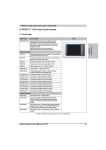
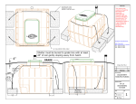
INSTALLATION AND MAINTENANCE INSTRUCTIONS MACERATOR PUMP Model: T10069 12v Macerator Pump, 13 GPM This TRAC Macerator Pump is designed specifically for sanitation waste and fish box evacuations. The pump self-primes to six feet and incorporates a heavy-duty motor with seamless motor tube and O-ring sealed end frames. The 13 gallons (49.2 l) per minute flow rate conveniently empties any tank in minutes while the high-speed rotary cutter shreds waste, producing a higher discharge capacity. For optimum performance and life, install the pump close to the tank. This macerator will not handle hard objects, rags or feminine products. If you have any questions, difficulty installing or maintaining this product, TRAC is here to help! First READ THIS MANUAL. If you still need help, call us from 9 am to 4 pm (central time) Monday – Friday. (615) 462-6224 Note: At this time, we provide Phone Support in English only. INSTALLATION AND MAINTENANCE INSTRUCTIONS Specifications Motor: Lead wires: Fuse: Pump Type: Duty Cycle: Ports Inlet: Outlet: Impeller: Blade: Typical Flow: Max Amp Draw @ 12v: MACERATOR PUMP Seamless can motor, 1/8 hp, thermally protected, ignition protected 14 GA See motor label for fuse size Flexible impeller Intermittent duty only Inlet 1-1/2" (38.1mm) Barb 1-1/2" (38.1mm) 1” (25mm) hose barb Polyurethane 316 stainless 13 GPM (49.2 LPM) 11 Please read and save these instructions. Read carefully before attempting to assemble, install, operate or maintain this pump. Protect yourself and others by observing all safety information. Failure to comply with instructions could result in personal injury and/or property damage! Retain instructions for future reference. READ and UNDERSTAND the Owner's Manual completely before using this Pump. Assemble, test and use only in accordance with this Owner's Manual instructions. Installation Mounting - This pump is self-priming. The pump should be located in an area that is dry and provides ventilation. DO NOT locate pump near combustible material. The surface temperature of the motor may exceed 121℃. The pump may be mounted in any position. However, if mounting the pump vertically the pump head should be in the down position so that in the unlikely event of a leak, fluid will not enter the motor. Secure rubber feet with fasteners. DO NOT compress feet, doing so will reduce ability to isolate vibration and noise. Electrical Connections - If the pump is operated in an area containing flammable vapors, the wire leads must be joined by an insulated wire connection. Inadequate wire connections can spark, resulting in explosion, property damage, injury or death. Pump must be protected with proper size fuse as specified on the motor label. Pump should be operated on a separate circuit. Pump should be connected to properly sized momentary switch. This prevents pump from damage due to long periods of dry run condition. Switch should be near pump. This will allow operator to hear change in pump sound when tank is empty. NOTE: For proper operation motor must rotate counterclockwise when viewed from pump end. Electrical Installation Checklist Separate circuit from power source Proper size momentary switch mounted near pump Proper wire size to length (14g up to 20’ (6.1m), 12g up to 30’ (9.1m)) Proper fuse size and type (see label on pump) Insulated wire connectors Plumbing Connections Pump should be mounted as near as possible to tank to minimize dry run. Pump is self-priming to a five-foot lift. To maximize efficiency, mount near the holding tank. INLET: Always install pump with a shut-off valve between pump and holding tank. Hose: Use 1-1/2” (38.1mm) ID [non-collapsible vacuum rated] hose on inlet [suction] side. Use stainless steel hose clamps on all sanitation connections. Flange: To mount 1-1/2” (38.1mm) female flange, inlet barb must be cut off just before threads. Seal threads and hand tighten. Any air leak on inlet side can cause pump to run dry and can damage impeller and housing. Check all inlet hose connections, even those on deck plates. All hose runs should be smooth with no kinks or sharp angles. OUTLET: Use 1” (25mm) minimum ID hose on discharge side of pump. Connect to thru-hull fitting above highest heeled point above waterline. Vented loop installations must vent at least 10” (254mm) above highest heeled point above waterline. Use stainless steel hose clamps on all sanitation connections. ! Operation - INTERMITTENT USE ONLY! Pump switch must be near pump and tank so operator can hear pump running. Make sure shut-off valve to pump and dump valve [if equipped] are both open. Turn on momentary switch and pump out tank. When tank is empty, pump will get louder with a high pitch sound. Immediately turn pump off, or damage to impeller and housing will occur. Do not run pump dry for more than 15 – 20 seconds. Flush tank and pump with water after each use. This macerator will handle normal waste, tissues, cigarettes, fish scales, etc. It is not designed to handle large hard objects such as large bones or fruit pits. Maintenance and Storage To service the pump, disconnect power to the pump. Perform maintenance or repairs. Follow the directions below to disassemble and reassemble the pump. Test after servicing. Flush with water after each use and check wire connections occasionally. After periods of non-use, impeller can stick. To loosen, open rear shaft cover and turn motor shaft clockwise with a flat tip screwdriver. Then replace shaft cover. For extended periods of non-use, pump impeller can be lubricated by running a small amount of mineral oil through holding tank system. Turn off all power and disconnect battery before starting to disassemble! Rear end cap/ motor shaft slot access: 1. Loosen end cap screws. 2. Rotate shaft cover to access slot on motor shaft. 3. Turn shaft clockwise. Pump disassembly: 1. Remove cover screws. 2. Remove cutter housing. 3. Remove hex nut and cutter blade. 4. It may be necessary to hold the motor shaft steady. Insert a screwdriver into slot on motor shaft, or slip a thin wrench (9/32” [7mm]) behind blades onto flat of motor shaft. 5. Remove top wear plate, gaskets, impeller and bottom wear plate. 6. Remove impeller housing. Pump reassembly: 1. Make sure shaft seal is inserted properly into rear of impeller housing. 2. Seat bottom wear plate into housing (install before impellor). 3. Slide impeller housing onto motor shaft. Twist impeller onto shaft and into housing with a counterclockwise motion. 4. Install gaskets and top wear plate. 5. Install cutter blades and align with motor shaft flat. 6. Secure motor shaft with screwdriver or wrench (9/32”) [7mm] and tighten hex nut. 7. Position seals and cutter housing in place, and install cover screws. PARTS If ordering a part, provide the pump model number as well as the part item number shown. Item 1 2 3 4 5 6 7 8 9 10 11 Description Motor assembly Impeller Housing Impeller Bottom Wear Plate Gasket Top Wear Plate Gasket Cutter Blade Hex Nut Cutter Housing Cover Screw(s) Quantity 1 1 1 1 1 1 1 1 1 1 4 TRAC Macerator Pump Limited Warranty This limited warranty is provided by TRAC Outdoor Products Co (TRAC) to the original consumer purchaser (purchaser) of the TRAC Pump. This limited warranty is not transferable to any other party. TRAC will at its option repair or replace any part(s) of the TRAC Pump which may be found by TRAC to be defective within three (3) years of purchase. TRAC will pay the shipping cost to the purchaser for any part(s) which may be shipped by TRAC. For warranty repair or replacement, the purchaser must provide dated proof of purchase and notify TRAC of the request for warranty service. The purchaser will notify TRAC by email at [email protected] or by phone at 615-462-6224 for warranty service. TRAC will attempt to provide parts needed to repair the pump. DO NOT RETURN PUMP TO TRAC! Contact TRAC for instructions. The purchaser must use reasonable care in maintenance and operation of the product in accordance with this manual. Failure to follow the instructions in the manual will void the warranty. This warranty covers defects in material or workmanship of the TRAC pump. This warranty does not cover failure that results from misuse, improper installation, accident, abuse, neglect, modification, or improper maintenance. There is no other express warranty. Implied warranties, including those of merchantability and fitness for a particular purpose, are limited to one (1) year from the date of purchase. Any damage to watercraft resulting from proper or improper use of this TRAC pump is not covered under this warranty. Costs of installation or repair by service centers or marine repair facilities are not covered by this warranty. This is the exclusive remedy and any liability for any and all incidental or consequential damages or expenses whatsoever is excluded. Some states do not allow limitations on how long an implied warranty lasts, or do not allow exclusion or limitation of incidental or consequential damages, the above limitations may not apply to you. This limited warranty gives you specific legal rights, and you may also have other rights which vary from state to state. TRAC Outdoor Products Company 251A Mayfield Drive Smyrna, TN 37167 www.trac-outdoor.com [email protected] 615/462-6224