1
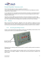
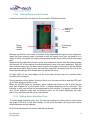
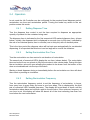
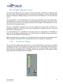
Automat ed Drum Dispenser
User Manual
VALE-TECH LIMITED
Unit 12, Depot Road, Newmarket, Suffolk CB8 0AL, UK
Tel: +44 (0) 1638 668583/668593
Fax: +44 (0) 1638 676720
E-mail: sales@vale -tech.co.uk
Introduction
This Manual provides the user with a comprehensive guide to the machine.
The Manual identifies the requirements for the initial installation of the machine and
provides information for the effective operation of the machine on a day-to-day basis,
including maintenance, to ensure a high standard of ink dispensing can be consistently
achieved.
The Service section of this manual enables the user to identify any spare parts that may
need to be ordered for the machine. This product has been manufactured to the highest
standards; however, should any difficulties arise, before requesting technical support, a
speedier resolution can usually be reached by referring to the trouble-shooting guide.
The Service Log at the back of this manual serves to provide contact information. Should
assistance be required please refer to the contact details supplied within this section.
Forms available in this section allow the service history of the machine to be recorded for
future reference.
Drum Dispenser
November 2007
2
Vale Tech Automated Drum Dispenser
Introduction
2
Contents
3
Certificate of Conformity
5
1
Drum dispenser overview
6
2
LA Controller
8
2.1
Control unit features
7
2.2
Product operation overview
8
2.3
Set up
9
2.3.1 Accessing the setting controls
9
2.3.2 Setting empty and full levels
10
2.3.3 Setting alarm activation point
10
Operation
11
2.4.1 Setting dispense time
11
2.4.2 Setting recirculation run time
11
2.4.3 Setting recirculation frequency
11
2.4.4 Timed dispense
12
2.4.5 Timed dispense cancel
14
2.4.6 Manual dispense
14
2.4.7 Recirculation operation
14
2.4.8 Level sensor display
15
2.4.9 Low ink alarm and alarm mute
16
2.4
Drum Dispenser
November 2007
3
Vale Tech Automated Drum Dispenser
INSTALLATION
3
4
17
Connection of services
18
3.1
Connecting air supply
18
3.2
Connecting electrical supply
18
Setting up
19
4.1
Control unit
19
4.2
Loading drum onto dispenser
20
4.3
Priming pump
21
4.4
General operation
24
4.4.1 Recirculation mode
24
4.4.2 Ink level sensor
24
5
Ink filter
25
6
Ink valve and recirculation valve
26
7
Troubleshooting
27
8
Spare parts
29
9
Diaphragm pump
30
9.1
30
Manual
SERVICE LOG
38
10
Information
39
11
Drawings supplied
40
12
Contact information
41
13
Service history
42
Drum Dispenser
November 2007
4
Declaration of Conformity & Quality
Vale-Tech Limited Hereby Declares That
Machine:
Project:
Is in conformity with the provisions of the machinery directives as listed below: The Machinery Directive, 98/37/EC – “Machinery is described in the Directive as "an assembly
of linked parts or components, at least one of which moves, with the appropriate actuators, control
and power circuits, etc., joined together for a specific application, in particular for the processing,
treatment, moving or packaging of a material". The manufacturer is responsible for verifying
whether a particular product falls within the scope of the Machinery Directive.”
The Pressure Equipment Directive, 97/23/EC – “ The directive provides control over equipment
subject to pressure” Pressure equipment being vessels, piping, safety accessories and pressure
accessories. A pressure assembly being several pieces of pressure equipment assembled to form
an integrated functional whole.
The EMC Directive, 89/336/EEC – “The Directive applies to most electrical and electronic
apparatus, that is, finished products and systems that include electrical and electronic equipment.”
The Low Voltage Directive, 73/23/EEC – “Broadly the Regulations apply to most consumer,
commercial and industrial electrical equipment designed for use within the voltage ranges 50 V ac
to 1,000 V ac and 75 V dc to 1,500 V dc.”
Remarks & restrictions for this dec laration
This declaration is no longer valid if any changes are made to the machine, which is not
corresponding to the abovementioned standards.
Place and date:
Newmarket
G Adlem:
Mechanical Engineering
C Stapleton:
Electrical Engineering
M Hughes:
Director
N Scott:
Director
Representing:
Vale-Tech Ltd
12 Depot Road
Newmarket
Suffolk CB8 0AL
United Kingdom
Drum Dispenser
November 2007
5
1
Automated drum dispenser overview
1” Diaphragm Pump
Pump Feed Hose
Control Unit
Air Supply Inlet
Re-Circulation Valve
Dispense Valve
Recirculation Hose
Ink Filter
Splash Guard
Drip Tray
Pump Feed Hose
Blend Container
Support Tray
Drum Dispenser
November 2007
6
Automated drum dispenser overview (cont)
Mains Power Supply In
Pump Air Supply
Regulator
Air Manifold
Valve Actuator Supply
Regulator
Product Identification
Label
Drum Restraining
Strap
Level Sensor
Pump Stand
Drum Dispenser
November 2007
7
2
LA Controller
2.1 Control unit features
Re-circulation Frequency
Dispense Time
Countdown Timer
Countdown Timer
Recirculation Run
Re-circulation Run Time
Level Indicator LED’s
Time Control
Countdown Timer
Recirculation
Frequency
Control
Low Ink
Indicator
Alarm
Muted
Indicator
Alarm Mute
Timed Dispense
Button
In Operation
Manual Dispense
Button
Timed Dispense
Button
Drum Dispenser
November 2007
Recirculation In
Operation
Cancel Timed
Dispense Button
Dispense Time
Control
Mode Switch
8
2.1 Control unit features (cont)
Pneumatics
Output Socket
Alarm Sounder
Level Sensing
Probe Input Socket
Mains power
2.2
?
Product Operation Overview
Set-up
Accessing the Setting Controls
Setting Empty and Full Levels
Setting Alarm Activation Point
?
Operation. - Set Mode
Setting ‘Dispense Time’
Setting Re-circulation ‘Run Time’
Setting Re-circulation ‘Frequency’
?
Operation. - Run Mode
Timed Dispense
Timed Dispense Cancel
Manual Dispense
Re-circulation Operation
Level Sensor Display
Low Ink Alarm and Alarm Mute
Drum Dispenser
November 2007
9
Product Operation Overview (cont)
The LA Controller has two modes of operation; set and run.
In set mode recirculation period and time can be set along with timed dispense duration
using the three rotary controls.
In run mode the timer is activated to provide automatic recirculation, timed dispensed are
performed based on the duration set in set mode, and manual dispenses can be made
using the manual button.
The three numerical LED’s provide information on the time functions set, and the eight
LED’s of the level display indicates the amount of product remaining in the drum. A further
two LED’s compliment the level display with muted alarm and low ink level indication.
2.3
Set-up
Before using the Drum Dispenser, calibration of the Level indicator to display the correct
product level in the drum, will be required. If this is not set, the wrong level will be shown
and could prevent the product from being dispensed with a premature an alarm condition.
2.3.1
Accessing the Setting Controls
Access to the empty and full level setting controls can be gained by the removal of the
access panel found on the left hand side of the controller.
Access Panel
Retaining Screws
Remove the two retaining screws and the panel to reveal the setting controls mounted on
the PCB within.
Apply power to the controller; there is no power switch on the Controller and it will power
up as soon as the supply is applied. The alarm may sound when power is applied, and
this is normal.
Drum Dispenser
November 2007
10
2.3.2 Setting Empty and Full Levels
Locate and identify the two switches on the smaller PCB shown below.
Low Level
Setting
Preset
Empty
Setting
Switch
Full Setting
Switch
Remove the lid from a full drum of product to be dispensed through the drum dispenser.
Insert the level sensing probe (mounted on the ink supply hose) into the product to a
depth of 20mm and press the empty setting switch shown above which will set the empty
point.
Replace the lid, place the full drum on the drum stand and secure with the retaining strap.
See section 4.2 of this manual for safe placement of drum onto drum dispenser. With the
drum inclined away from the drum stand, position the larger screw cap on the lid farthest
from the drum stand. Remove this cap and fully insert the ink supply hose into the drum.
Press the full setting switch shown above to set the full point.
All eight LED’s of the level display on the front panel should now be lit and the alarm
sounder will be silenced.
During operation of the system, the level of the ink in the drum will drop and the LED’s will
go out from green to amber to red.
When the red LED goes out the empty alarm indicator will come on, this is when the ink
level has dropped to a point below which a reliable dispense can be achieved. This
indicator is also red and will be accompanied by the sounder. The empty condition will
shut off the dispense valve and recirculation valve, so no further dispenses can take
place. Any remaining ink will not be recirculated.
2.3.3 Setting Alarm Activation Point
To set the alarm activation point, turn the low level setting pot (shown above) until just the
red empty LED is lit on the level display. At this point the alarm will sound and further
timed dispenses will be inhibited.
Re-fit the access panel and secure with the two screws.
Drum Dispenser
November 2007
11
2.4 Operation
In set mode the LA Controller can be configured for the required timed dispense period,
recirculation run time and recirculation period. Turning the mode key switch to the set
position enters this mode.
2.4.1
Setting Dispense Time
Turn the dispense time control to set the time required to dispense an appropriate
quantity of product for the container being used.
The dispense time is indicated by the first numerical LED marked dispense time, (shown
below). Initially, the dispense time is displayed in seconds (one to fifty-nine), indicated by
the use of two decimal points, then in minutes (one to thirty-six) with no decimal points.
This is the time period the dispense valve will be kept open automatically for un-attended
dispensing. It is important that this time is not so large as to over-fill the container.
2.4.2
Setting Recirculation Run Time
Turn the recirculation run time control to set duration of recirculation.
The second pair of numerical LED’s display the run time, (shown below). The recirculation
time can be set from one minute to fifty nine minutes in one minute steps. During this time
the re-circulation valve will open allowing the product to be drawn from the bottom of the
drum re-circulated back into the top of the drum.
Starting a timed dispense during or immediately before the recirculation run time will abort
the current or pending re-circulation.
2.4.3
Setting Recirculation Frequency
Turn the recirculation frequency control to set the frequency of recirculation, in hours;
from every hour to every thirty six hours in one hour steps. This is displayed by the third
pair of numerical LED’s marked frequency. The display will count down in hours until the
recirculation takes place and will then reset to the set value. If the minimum frequency of
one hour is set, the display will show 00 almost all of the time indicating less than one
hour before the next recirculation.
Drum Dispenser
November 2007
12
Setting Recirculation Frequency (cont)
Note. The timer is reset each time Set Mode is entered.
To store the values and start the recirculation timer turn the mode key back to the run
position. The key can be removed when in the run position to prevent changes to the
stored data. This is preferable to avoid the timer from being reset and incorrect values
being set for the three controls. Store the key in a safe place so that the timings can be
changed if required.
2.4.4
Timed Dispense
Place a suitable container beneath the dispense head, press the timed button on the LA
Controller, the timed dispense LED will light red (shown below) and the dispense time
counter will count down from the pre-set time to zero.
Timed Dispense showing 53 Seconds
During the count down the dispense valve will open and deliver the product to the
container beneath it. At the end of the dispense time the counter will return to the pre-set
value and the red LED will extinguish.
Drum Dispenser
November 2007
13
Timed Dispense (cont)
If the dispense time is greater than fifty-nine seconds, the counter display will alternate
between minutes and seconds; the seconds being indicated by the use of the decimal
points (Fifty-three seconds is shown above).
If the controller enters an alarm condition during a timed dispense, the counter will
continue to count down, however the dispense valve will close stopping the product from
flowing.
2.4.5 Timed Dispense Cancel
In the event that a timed dispense needs to be cancelled pressing the cancel button will
stop the dispense and reset the dispense time timer.
2.4.6
Manual Dispense
To perform a manual dispense, press and hold the manual dispense button. The dispense
valve will open and ink will be delivered into the container. Release the button when the
required amount of ink has been dispensed. Manual dispense can be used to top-up a
timed dispense.
2.4.7
Re-circulation Operation
Re-circulation takes place at a frequency determined by the frequency timer. This
determines how often the recirculation valve will open and is set in hours. i.e. every hour,
every two hours, every five hours etc. (A recirculation frequency of five hours is shown
below).
The timer is started when run mode is entered (from set mode). The next recirculation will
start at the same time every hour, two hours, etc. at the time value which was entered.
The timer will reset if set entered and then run mode is re-entered.
Drum Dispenser
November 2007
14
Re-circulation Operation (cont)
The frequency display will count down to 00 when automatic recirculation is triggered, and
will then reset to the programmed time. During the recirculation run time, the red LED
below the frequency display will light, at the end of the recirculation run time the LED will
go out.
The recirculation run time determines how long the recirculation valve will remain open
and therefore how much of the product is recirculated from the bottom of the drum to the
top. This is set in minutes and is shown by the run time display. (This has been set to ten
minutes in the illustration above).
During a recirculation operation the run time display will count down 00 while the
recirculation LED is lit, after the set run time has elapsed the display will return to the set
time and the LED will go out.
If a timed dispense is in operation at the same time as a recirculation is scheduled to
start, the re-circulation will be aborted. If a timed dispense is started during a recirculation
run time, the re-circulation will be aborted.
Note. Avoid turning the controller off unnecessarily as this will reset the recirculation start
time. Automatic recirculation will not take place while the controller is switched off.
2.4.8
Level Sensor Display
The level sensor display provides an easy to read representation of the level of product
remaining in the drum. As the product is used, the level on the display will drop, and will
be indicated by the upper LED’s extinguishing from full to empty. When the red empty
LED is the only remaining LED lit, the alarm will sound and the low LED will light. Timed
dispenses and recirculations will be inhibited.
Drum Dispenser
November 2007
15
2.4.9
Low Ink Alarm and Alarm Mute
When the product level is at a minimum, the red empty LED of the level display will light;
the low LED will also light and the alarm will sound. This indicates that the drum must be
changed before any further dispenses can be achieved. If it is not convenient to change
the drum at this time, but the sounder is becoming an annoyance, it can be muted by
pressing the alarm mute button. The alarm LED will light whilst the alarm is muted. Do not
turn the controller off. This will reset the recirculation start time.
Drum Dispenser
November 2007
16
INSTALLATION
Drum Dispenser
November 2007
17
3
3.1
Connection Of Services
Connecting Air Supply
Connect a clean dry air supply of 6-bar minimum to the 16mm air inlet.
Pump Air Supply
Hose (12mm)
Air Supply To Valve
Actuators 6mm
Pump Air Supply
Regulator Adjuster
Pump Air Supply
Switch
Air Inlet
Hard Wall Hose
(16mm)
Pump Air Supply
Regulator
Air Filter
If 16mm Hard Wall Hose is not available a soft wall hose can be used with the provided
adaptor.
3.2 Connecting Electrical Supply
Connect mains 100-240V ac supply to the mains socket, on the back of the control unit.
Drum Dispenser
November 2007
18
4
Setting Up
4.1 Control unit
Drum dispenser dispensing operations are controlled by parameters set within the control
unit. The control unit functions are to control the dispense, level sensing, automatic batch
switching and automatic re-circulation of ink. The control unit will become active when the
mains power is switched on. Full instructions of it’s operation are detailed in section 2 of
this manual.
Control unit
front view
Dispense time,
recirculation
run
time/frequency
indicators
Dispense time,
recirculation
run
time/frequency
adjustment
Ink level
indicators
Control unit
rear view
Mains
power
Drum Dispenser
November 2007
Pneumatics
output
socket
Ink level
sensor probe
input socket
Manual/automatic
dispense, cancel timed
dispense and alarm
mute buttons
Alarm
sounder
19
Setting Up (cont)
4.2 Loading Drum Onto Dispenser
Using a drum trolley, move the drum of ink close to the rear of the drum dispenser. With it
flat on the floor, remove the screw in caps from the drum lid and insert the pump feed and
recirculation hoses.
Set the full and empty ink level sensors as detailed in section 2 of this manual.
Carefully locate the drum onto the rear of the drum dispenser and secure it in place using
the ratchet strap provided.
Ratchet
strap
Drum Dispenser
November 2007
20
Setting Up (cont)
4.3 Priming Pump
Having connected the mains power and the air supply to the drum dispenser, the
following must be undertaken:
Set the pump pressure regulator to 2.5bar. This is the recommended starting
pressure. Turn on the air supply to the pump using the pump air supply switch.
Pump Air Supply
Switch
Pump Regulator
and Gauge
Set the ink valve pressure regulator to 5.5bar.
Set to 5.5bar
Drum Dispenser
November 2007
21
4.3 Priming Pump (cont)
Place an empty container onto the dispense drip tray, unlock the handle and adjust
the height of the blend container support tray so that there is approximately 30mm
clearance between the top of the container and the underside of the splash guard as
shown below. Ensure support tray is locked in position before proceeding.
Blend Container
Support Tray
Locking Handle
Locate the restrictor on the top of the pump.
Pump restrictor
In the centre of the restrictor is a socket head bolt or slotted adjuster. Turn this bolt
anti-clockwise (upwards) to de-restrict the pump, stop when the bolt comes into
contact with limiter pin. This will allow free flow of ink through the pump, and can be
adjusted if necessary when the pump has been primed with ink.
Drum Dispenser
November 2007
22
4.3 Priming Pump (cont)
Press the manual dispense button on the control unit until any residual water, (from
the factory testing of the dispenser), and ink from the drum is being dispensed into the
container. The pump may slow as ink enters the system and starts to dispense.
Adjust the restrictor by turning the socket head bolt clockwise. This will result in the
cycle time of the pump slowing. Adjust this until a one -second -pump cycle is
achieved. If required the air pressure can be increased to stop the pump from stalling.
It is advisable to increase the air pressure slowly until just enough pressure is applied
for reliable operation.
The pump should now operate to its optimum flow rate.
If the pump stalls for any reason, turn the pump air supply switch to the off position for
at least 10 seconds. This will allow the pump to clear itself. Turn the pump air supply
switch back to the on position. With a container in place below the dispense valve,
press manual dispense to allow the pump to operate. This should allow the pump to
automatically re-start itself.
If the pump does not restart itself immediately or pumps intermittently, follow setting
up procedure in the Service Section.
Drum Dispenser
November 2007
23
4.4 General operation
Having primed the pump, the ink contained within the drum can be dispensed either
by a timed dispense, as described in section 2.4.4 or manually as described in section
2.4.5.
Before dispensing ink, ensure the height of the blend container support tray with the
drip tray are set correctly for the height for the container to be used, and not too low
that splashing of the ink may occur due to the gap between the top of the container
and the underside of the splash guard being too great. The splash guard has a hole in
the centre which is lined up with the dispense valve outlet nozzle. Ensure the time
allocated to the timed dispense is adequate to fill the container to the desired level,
and not too long so it can be overfilled.
4.4.1 Recirculation mode
In recirculation mode, the ink is pumped from the bottom of the drum, through the
recirculation ink valve and back through the recirculating hose to the top of the drum. If
the recirculation mode is required to be in operation due to setting up or separation of
ingredients used in the ink, this can be configured as described in section 2.4.3. The
frequency and time for recirculation will be specific to the type of ink being dispensed.
4.4.2 Ink level sensor
The ink level sensor probe is mounted on the pump feed hose and detects the amount
of ink remaining in the drum. The probe terminates in the digitiser box and a cable
runs from here to the LA Controller which displays the level by means of the level
indicator LEDs on the front panel. Set up of this function is described in section 2.3.2
of this manual.
Digitiser
box
Digitiser
cable
Level
sensor
probe
Pump
feed hose
Drum Dispenser
November 2007
24
5 Ink Filter
The ink filter is positioned on the right side of the machine and is part of the pump feed
hose line. It comprises an outer casing, with an enclosed mesh filter. Its purpose is to
filter debris from the ink before it reaches the ink container. To remove the filter for
cleaning, first switch off the air supply to the pump, and with a suitable container on
the drip tray, press the manual dispense button to release the pressure in the ink feed
hose. When the flow subsides, press the red button on top of the filter to release and
residual pressure in the ink filter. Wearing suitable protective gloves, overalls and
safety glasses, hold the blue outer casing of the filter with both hands and unscrew it.
The filter and casing must be kept in a vertical position to avoid spilling and of the
contents. Empty the contents of the filter and casing into a waste container and place
the casing and filter in a suitable location for cleaning. Once cleaned, replace the filter
and casing, and switch on the air supply to the pump.
Pressure
release
button
Filter
assembly
Filter casing
Drum Dispenser
November 2007
Mesh filter
25
6
Ink valve and recirculation valve
Ink is dispensed into the container via the ink valve. This comprises a valve body and
an actuator which is controlled by the LA Control Unit to dispense as required. As the
actuator is activated, the dispense nozzle in the valve body is opened and the ink is
pumped either to complete a timed dispense or for the duration of the manual
dispense button being pressed. The ink dispense valve incorporates an anti drip fitting
to the outlet of the nozzle.
Ink return
hose
Ink feed
hose
Ink recirculation
valve and
actuator
Ink
dispense
valve and
actuator
The recirculation valve comprises a valve body and an actuator which is also
controlled by the LA Control Unit. It will open as determined by the setting of the
control unit. As the actuator is activated, the restrictor in the valve body is opened and
the ink is pumped through the return hose and back into the drum.
Drum Dispenser
November 2007
26
7
Troubleshooting
If the drum dispenser should fail to operate, check the following:
Power to LA controller unit. Check the level sensor indicators and the numerical indicators
are lit. If not, check the mains power supply to the dispenser.
Compressed air to the air supply manifold is good. A clean dry air supply of 6bar
minimum is required for correct operation.
Compressed air supply to the pump is set to required pressure and is switched on. Set to
default pressure of 2.5bar at the factory, but this may differ slightly dependent on ink
viscosity. Adjust the regulator to obtain pressure to the required value.
Set the ink
pump pressure
to 2.5bar
Check the air to the dispense and re-circulate valves is set correctly. This is set by means
of the regulator mounted on the side of the control box. This is set to 5.5bar at the factory
and is the recommended pressure.
Set the ink
pump pressure
to 5.5bar
Drum Dispenser
November 2007
27
Troubleshooting (cont)
The empty alarm LED is lit and the empty alarm sounder is sounding. In this mode the
dispenser will not dispense. Replace the empty drum with a full drum to continue. If there
is still a reasonable quantity of ink in the drum, adjust the level sensor thresholds. See
section 2.3.2.
The pump has stalled. If this occurs, turn the air to pump switch off and then on again.
This will usually restart the pump.
The dispense valve has stuck open. If this occurs, turn the air supply to the pump off and
place a container under the dispense outlet to catch any residual ink. Call for a service
engineer.
The recirculate valve is stuck open. If this occurs, the pump will operate even when the
timer is off, and will continue to recirculate during a dispense. This will slow the dispense
and should be rectified as soon as possible. Call for a service engineer.
The level sensing is inaccurate. Re-calibrate the level sensing circuit. See section 2.3.2.
Drum Dispenser
November 2007
28
8
Spare parts
8.1 General Parts List
Item
1
2
3
4
5
6
7
8
9
10
11
12
13
14
15
16
17
18
19
20
21
22
23
24
25
26
27
Drum Dispenser
November 2007
Dispense valve including actuator
Recirculating valve including actuator
Actuator
Filter complete
Filter Mesh
Ink feed hose part 1
Ink feed hose part 2
Ink feed hose part 3
Recirculation hose
Hose clip
Air manifold complete
Main air regulator and gauge
Actuator air regulator and gauge
Ink valve actuator solenoid
Recirculation valve actuator solenoid
Ink pump air switch
LA controller complete
Dispenser pump assembly
Dispenser pump wet service kit
Dispenser pump air motor service kit
Ratchet strap
Alarm sounder
Level sensor probe
Splash guard
Drip tray complete
Blend container support locking handle
Anti drip nozzle
SP-9189
SP-9197
SP-9178
SP-9530
SP-9531
SP-9332
SP-9332
SP-9332
SP-9330
SP-9343
SPSPSPSPSPSPSPSP-9341
SP-9583
SP-9585
SP-9586
SP-9003
SPSPSPSPSP-9090
29
9
Diaphragm pump
9.1
Drum Dispenser
November 2007
Manual
30
Manual (cont)
Drum Dispenser
November 2007
31
Manual (cont)
Drum Dispenser
November 2007
32
Manual (cont)
Drum Dispenser
November 2007
33
Manual (cont)
Drum Dispenser
November 2007
34
Manual (cont)
Drum Dispenser
November 2007
35
Manual (cont)
Drum Dispenser
November 2007
36
Manual (cont)
Drum Dispenser
November 2007
37
SERVICE
LOG
Drum Dispenser
November 2007
38
10 Information
This Service Log serves to provide contact information; should additional assistance be
required please refer to the contact details supplied below. Forms available at the end of
this section allow space for the service history of the machine to be recorded for future
reference.
Drum Dispenser
November 2007
39
11 Drawings supplied
Pneumatic circuit diagram
Drum Dispenser
November 2007
40
12 Contact Information
If you require any additional assistance or have any queries, please contact
Vale-Tech
Telephone:
+44 (0) 1638 668593
Fax:
+44 (0) 1638 676720
Email:
[email protected]
Website:
www.vale-tech.co.uk
Address:
VALE-TECH LIMITED
Unit 12
Depot Road
Newmarket
Suffolk
CB7 OAL
UK
Drum Dispenser
November 2007
41
13 Service History
13.1 Machine Fault/Maintenance Log
Date
Drum Dispenser
November 2007
Action Taken
Signed
42
Machine Fault/Maintenance Log (cont)
Date
Drum Dispenser
November 2007
Action Taken
Signed
43