1
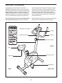
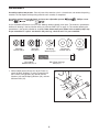
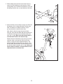
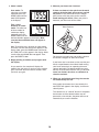
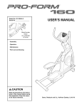
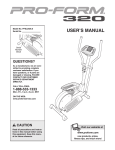
Model No. WLEVEX1216.0
Serial No.
USER’S MANUAL
Serial Number
Decal
QUESTIONS?
As a manufacturer, we are committed to providing complete
customer satisfaction. If you
have questions, or if there are
missing parts, please call:
08457 089 009
Or write:
ICON Health & Fitness, Ltd.
Customer Service Department
Unit 4
Revie Road Industrial Estate
Revie Road
Beeston
Leeds, LS118JG
UK
email: [email protected]
CAUTION
Read all precautions and instructions in this manual before using
this equipment. Keep this manual
for future reference.
Visit our website at
www.iconeurope.com
TABLE OF CONTENTS
IMPORTANT PRECAUTIONS . . . . . . . . . . . . . . . . . . . . . . . . . . . . . . . . . . . . . . . . . . . . . . . . . . . . . . . . . . . . . . . .2
BEFORE YOU BEGIN . . . . . . . . . . . . . . . . . . . . . . . . . . . . . . . . . . . . . . . . . . . . . . . . . . . . . . . . . . . . . . . . . . . . . .3
ASSEMBLY . . . . . . . . . . . . . . . . . . . . . . . . . . . . . . . . . . . . . . . . . . . . . . . . . . . . . . . . . . . . . . . . . . . . . . . . . . . . . . .4
HOW TO OPERATE THE EXERCISE CYCLE . . . . . . . . . . . . . . . . . . . . . . . . . . . . . . . . . . . . . . . . . . . . . . . . . . . .8
MAINTENANCE AND TROUBLESHOOTING . . . . . . . . . . . . . . . . . . . . . . . . . . . . . . . . . . . . . . . . . . . . . . . . . . . .11
CONDITIONING GUIDELINES . . . . . . . . . . . . . . . . . . . . . . . . . . . . . . . . . . . . . . . . . . . . . . . . . . . . . . . . . . . . . . .12
PART LIST . . . . . . . . . . . . . . . . . . . . . . . . . . . . . . . . . . . . . . . . . . . . . . . . . . . . . . . . . . . . . . . . . . . . . . . . . . . . . .14
EXPLODED DRAWING . . . . . . . . . . . . . . . . . . . . . . . . . . . . . . . . . . . . . . . . . . . . . . . . . . . . . . . . . . . . . . . . . . . .15
ORDERING REPLACEMENT PARTS . . . . . . . . . . . . . . . . . . . . . . . . . . . . . . . . . . . . . . . . . . . . . . . . . .Back Cover
IMPORTANT PRECAUTIONS
WARNING:
To reduce the risk of serious injury, read the following important precautions before using the exercise cycle.
8. Wear appropriate clothes while exercising; do
not wear loose clothes that could become
caught on the exercise cycle. Always wear
athletic shoes for foot protection.
1. Read all instructions in this manual and all
warnings on the exercise cycle before using
the exercise cycle.
2. Use the exercise cycle only as described in
this manual.
9. The exercise cycle should not be used by
persons weighing more than 115 kg (250 lbs.)
3. It is the responsibility of the owner to ensure
that all users of the exercise cycle are adequately informed of all precautions.
10. The pulse sensor is not a medical device.
Various factors may affect the accuracy of
heart rate readings. The pulse sensor is
intended only as an exercise aid in determining heart rate trends in general.
4. The exercise cycle is intended for home use
only. Do not use the exercise cycle in
a commercial, rental, or institutional setting.
11. Always keep your back straight while using
the exercise cycle; do not arch your back.
5. Keep the exercise cycle indoors, away from
moisture and dust. Place the exercise cycle
on a level surface, with a mat beneath it to
protect the floor or carpet. Make sure that
there is enough clearance around the exercise cycle to mount, dismount, and use it.
12. If you feel pain or dizziness while exercising,
stop immediately and cool down.
13. The warning decal shown on page 3 has been
placed on the exercise cycle. If the decal is
missing or illegible, call the telephone number
on the front cover of this manual and request
a free replacement decal. Apply the decal in
the location shown.
6. Inspect and properly tighten all parts regularly. Replace any worn parts immediately.
7. Keep children under the age of 12 and pets
away from the exercise cycle at all times.
WARNING:
Before beginning this or any exercise program, consult your physician. This
is especially important for persons over the age of 35 or persons with pre-existing health problems.
Read all instructions before using. ICON assumes no responsibility for personal injury or property
damage sustained by or through the use of this product.
2
BEFORE YOU BEGIN
Congratulations for selecting the new WESLO®
PURSUIT R 60 exercise cycle. Cycling is one of the
most effective exercises for increasing cardiovascular
fitness, building endurance, and toning the body. The
PURSUIT R 60 exercise cycle offers a selection of
features designed to let you enjoy this healthful exercise in the convenience and privacy of your home.
after reading this manual, please see the front cover of
this manual. To help us assist you, note the product
model number and serial number before contacting us.
The model number is WLEVEX1216.0. The serial
number can be found on a decal attached to the exercise cycle (see the front cover of this manual for the
location of the decal).
For your benefit, read this manual carefully before
you use the exercise cycle. If you have questions
Before reading further, please familiarize yourself with
the parts that are labeled in the drawing below.
Handgrip Pulse Sensor
Console
Adjustment Handle
Handlebar
Resistance Control
FRONT
Seat
Seat Post Knob
Seat Knob
Pedal/Strap
RIGHT SIDE
REAR
3
ASSEMBLY
Assembly requires two persons. Place all parts of the exercise cycle in a cleared area and remove the packing
materials. Do not dispose of the packing materials until assembly is completed.
Assembly requires the included tools and your own adjustable spanner
driver
, and pliers
.
, Phillips screw-
As you assemble the exercise cycle, use the drawings below to identify small parts. The number in parentheses
below each drawing is the key number of the part, from the PART LIST on page 14. The number following the
parentheses is the quantity needed for assembly. Note: Some small parts shown in the assembly steps may
be pre-assembled. If a part is not found in the parts bag, check to see if it is pre-assembled.
M8 Nylon
Locknut (46)–3
M8 Acorn
Nut (35)–4
M8 Spring
Washer (59)–8
M8 x 20mm
Button Screw (51)–4
M8 Curved
Washer (44)–8
M8 Washer
(53)–3
M8 x 75mm Carriage
Bolt (16)–4
1. While another person lifts the rear of the Frame (1),
attach the Rear Stabilizer (7) to the Frame with two
M8 x 75mm Carriage Bolts (16), two M8 Curved
Washers (44), two M8 Spring Washers (59), and two
M8 Acorn Nuts (35).
1
35
59
44
7
35
59
44
1
16
4
2. While another person lifts the front of the Frame (1),
attach the Front Stabilizer (6) with two M8 x 75mm
Carriage Bolts (16), two M8 Curved Washers (44), two
M8 Spring Washers (59), and two M8 Acorn Nuts (35).
2
16
35
44
59
1
6
44
3. Attach the Seat (4) to the Seat Carriage (28) with three
M8 Washers (53) and three M8 Nylon Locknuts (46).
Note: The Washers and Nylon Locknuts may be
pre-attached to the underside of the Seat.
59
35
3
4
Next, slide the Seat Carriage (28) onto the Seat
Post (34). Insert the Seat Knob (20) into the Seat Post
and the Seat Carriage and turn the Seat Knob clockwise until it is tight. Make sure that the Seat Knob is
inserted into the hole in the Seat Carriage.
53
46
53
46
Remove the Seat Post Knob (29) by turning it counterclockwise. Next, insert the Seat Post (34) into the
Frame (1). Align one of the adjustment holes in the
Seat Post with the indicated hole in the Frame. Insert
the Seat Knob into the Frame and the Seat Post, and
turn the Seat Knob clockwise until it is tight. Make sure
that the Seat Post Knob is inserted into one of the
adjustment holes in the Seat Post.
20
Hole
29
5
28
34
1
4. While another person holds the Upright (2) in the position shown, connect the Upper Wire Harness (30) to
the Reed Switch Wire (31). Next, connect the
Resistance Cable (13) to the Lower Cable (40) in the
following way:
4
30
13
31
40
• See the inset drawing. Insert the end of the
Resistance Cable (13) through the connector from
the side shown. Next, press the small cylinder on the
end of the Resistance Cable into the indicated hole
in the connector.
• Pull the Resistance Cable (13) upward and insert it
into the hole in the top of the connector.
Be careful to
avoid pinching
the wires and
cables.
Carefully pull the excess Upper Wire Harness (30)
upward from the top of the Upright (2), push the
excess Cables (13, 40) down into the Frame (1), and
slide the Upright onto the Frame. Be careful to avoid
pinching the Wires and Cables. Next, attach the
Upright with four M8 x 20mm Button Screws (51), four
M8 Spring Washers (59), and four M8 Curved
Washers (44).
2
44
59
51
51
59
44
59
51
30
13
40
31
1
5. The Console (5) requires two 1,5V AA batteries; alkaline batteries are recommended. Remove the battery
cover from the Console. Insert two batteries into the
Console. Make sure that the batteries are oriented
as shown by the diagram inside the Console. Then,
reattach the battery cover.
5
Battery
Cover
Batteries
5
6
6. Have another person hold the Console (5) near the
Upright (2). Connect the console wire to the Upper
Wire Harness (30).
6
5
Console
Wire
Insert the excess console wire and Upper Wire
Harness (30) downward into the Upright (2). Slide the
Console (5) onto the Upright. Be careful to avoid
pinching the wires.
30
2
Be careful to
avoid pinching
the wires.
7. Position the Handlebar (3) inside the hinged bracket on
the Upright (2). Attach the Handlebar with the Handlebar
Cover (18), a Handlebar Spacer (21), and the
Adjustment Handle (17).
7
3
Connect the console pulse wires to the Pulse Wires (57)
as shown. Insert the excess wiring into the Handlebar
(3).
2
57
Console
Pulse Wires
8. Identify the Left Pedal (10), which is marked with an
“L”. Using an adjustable spanner, firmly tighten the
Left Pedal counterclockwise into the left arm of the
Crank (12). Tighten the Right Pedal (not shown) clockwise into the right arm of the Crank. Important:
Tighten both Pedals as firmly as possible. After
using the exercise cycle for one week, retighten
the Pedals. For best performance, the Pedals must
be kept tightened.
18
21
17
8
10
12
9. Make sure that all parts are properly tightened before you use the exercise cycle. Note: After assembly is
completed, some extra parts may be left over. Place a mat beneath the exercise cycle to protect the floor.
7
HOW TO OPERATE THE EXERCISE CYCLE
HOW TO ADJUST THE SEAT POST
HOW TO ADJUST THE PEDALING RESISTANCE
For effective exercise, the seat should
Seat
be at the proper
height. As you
Seat Post
pedal, there should
be a slight bend in
your knees when the
Post Knob
pedals are in the
lowest position. To
adjust the height of
Hole
the seat, first
remove the seat
post knob by turning
it counterclockwise. Next, slide the seat post up or
down to the desired position, and align one of the
adjustment holes in the seat post with the indicated
hole in the frame. Then, insert the knob into the frame
and the seat post, and turn the knob clockwise until it is
tight. Make sure that the knob is inserted into one
of the adjustment holes in the seat post.
To increase the
resistance of the
pedals, turn the
resistance control
clockwise; to
decrease the resistance, turn the control counterclockwise. Important:
Stop turning the
control when turning becomes difficult, or damage
may result.
HOW TO ADJUST THE HANDLEBAR
To adjust the handlebar, first loosen
the indicated adjustment handle by
turning it counterclockwise. Pivot the
handlebar forward
or backward to the
desired position and
then retighten the
handle.
HOW TO ADJUST THE SEAT
To adjust the seat,
loosen the seat knob
by turning it counterclockwise. Next,
slide the seat forward or backward
on the seat carriage
to the desired position, then turn the
seat knob clockwise
until it is tight.
Seat
Seat Knob
HOW TO ADJUST THE PEDAL STRAPS
To adjust the pedal
straps, first pull the
ends of the straps off
the tabs on the pedals. Adjust the straps
to the desired position, and press the
ends of the straps
back onto the tabs.
Resistance
Control
Strap
Tab
8
Handlebar
Handle
FEATURES OF THE CONSOLE
HOW TO USE THE CONSOLE
The easy-to-use console features six modes that provide instant exercise feedback during your workouts.
The console modes are described below.
Make sure that the console has batteries (see assembly step 5 on page 6). If there is a sheet of clear plastic
on the face of the console, remove it.
Note: You can set the console to display speed
and distance in either kilometers or miles. When
you insert batteries into the console, “KPH” will begin
to flash in the display. While “KPH” is flashing, you can
press the MODE button repeatedly to switch between
“KPH” (kilometers) and “MPH” (miles). A few seconds
after you have selected “KPH” or “MPH,” the unit of
measurement will be set.
Follow the steps below to operate the console.
1. Turn on the console.
To turn on the console, press any button on the
console or simply begin pedaling.
2. Set a workout goal if desired.
Scan (SCAN)—This mode displays the time, speed,
distance, odometer, calorie, and pulse modes, for a
few seconds each, in succession.
To set a time, distance,
or calorie-burning goal
for your workout, first
stop pedaling and wait
for the word STOP to
appear in the display.
Time (TMR)—This mode displays the elapsed time.
Note: If you set a time goal (see step 2), this mode will
display the time remaining in your workout.
Speed (SPD)—This mode displays your pedaling
speed, in kilometers per hour or miles per hour.
Next, press the MODE
button repeatedly until
the letters TMR, DST,
or CAL appear near
the lower edge of the
display. Make sure
that the word SCAN
does not appear.
Distance (DST)—This mode displays the distance you
have pedaled during your workout, in kilometers or
miles. Note: If you set a distance goal (see step 2),
this mode will display the distance remaining in your
workout.
Calorie (CAL)—This mode displays the approximate
number of calories you have burned during your workout. Note: If you set a calorie-burning goal (see step
2), this mode will display the number of calories still to
be burned in your workout.
Next, press the UP
button repeatedly to
set a goal. To set a
goal quickly, hold
down the UP button.
To reset the goal,
press the RESET
button.
Pulse (PULSE)—This mode displays your heart rate
when you hold the handgrip pulse sensors.
9
3. Select a mode.
5. Measure your heart rate, if desired.
Scan mode—To
select the scan mode,
repeatedly press the
MODE button until the
word SCAN appears
in the display.
If there are sheets of clear plastic on the metal
contacts of the handgrip pulse sensor, peel off
the plastic. Place your hands on the handgrip
pulse sensor, with your palms on the contacts.
Avoid moving your hands. When your pulse is
detected, your heart rate will be shown.
Time, speed,
distance, or calorie
mode—To select one
of these modes for
continuous display,
repeatedly press the
MODE button until the
desired selection appears in the display. Make
sure that the word SCAN does not appear in
the display.
Metal Contacts
Note: To reset the time, distance, or calorie mode,
first make sure that the word STOP appears in the
display. Next, press the MODE button until the letters TMR, DST, or CAL appear in the display. Make
sure that the word SCAN does not appear. Then,
press the RESET button.
For the most accurate heart rate reading, continue
to hold the handgrips for about 30 seconds.
4. Begin pedaling and follow your progress with
the display.
If your heart rate is not shown, make sure that your
hands are positioned as described. Avoid moving
your hands excessively or squeezing the metal
contacts too tightly. For optimal performance, periodically clean the metal contacts using a soft cloth;
never use alcohol, abrasives, or chemicals to
clean the contacts.
As you exercise, the console will display the
mode(s) that you select. If you have set a workout
goal, a tone will sound for several seconds when
you reach your goal.
6. When you are finished exercising, the console
will automatically turn off.
If the pedals do not move for a few seconds, the
word STOP will appear in the display, and the console will pause.
The console has an “auto-off” feature. If the pedals
do not move and the console buttons are not
pressed for a few minutes, the power will turn off
automatically to save the batteries.
10
MAINTENANCE AND TROUBLESHOOTING
BATTERY REPLACEMENT
Inspect and tighten all parts of the exercise cycle regularly. Replace any worn parts immediately.
If the console display becomes dim, the batteries
should be replaced; most console problems are the
result of low batteries. To replace the batteries, see
step 5 on page 6.
To clean the exercise cycle, use a damp cloth and a
small amount of mild detergent.
Important: To avoid damaging the console, keep
liquids away from the console and keep the console out of direct sunlight.
11
CONDITIONING GUIDELINES
During the first few minutes of exercise, your body
uses easily accessible carbohydrate calories for
energy. Only after the first few minutes of exercise
does your body begin to use stored fat calories for
energy. If your goal is to burn fat, adjust the intensity
of your exercise until your heart rate is near the lowest number in your training zone as you exercise.
WARNING:
Before beginning this or any exercise program, consult your physician. This is especially important for persons over the age of 35
or persons with pre-existing health problems.
For maximum fat burning, adjust the intensity of your
exercise until your heart rate is near the middle number in your training zone as you exercise.
The pulse sensor is not a medical device.
Various factors may affect the accuracy of
heart rate readings. The pulse sensor is
intended only as an exercise aid in determining heart rate trends in general.
Aerobic Exercise
If your goal is to strengthen your cardiovascular system, your exercise must be “aerobic.” Aerobic exercise is activity that requires large amounts of oxygen
for prolonged periods of time. This increases the
demand on the heart to pump blood to the muscles,
and on the lungs to oxygenate the blood. For aerobic
exercise, adjust the intensity of your exercise until
your heart rate is near the highest number in your
training zone as you exercise.
The following guidelines will help you to plan your
exercise program. Remember that proper nutrition
and adequate rest are essential for successful results.
EXERCISE INTENSITY
Whether your goal is to burn fat or to strengthen your
cardiovascular system, the key to achieving the
desired results is to exercise with the proper intensity.
The proper intensity level can be found by using your
heart rate as a guide. The chart below shows recommended heart rates for fat burning, maximum fat
burning, and cardiovascular (aerobic) exercise.
WORKOUT GUIDELINES
Each workout should include the following three parts:
A warm-up, consisting of 5 to 10 minutes of stretching
and light exercise. A proper warm-up increases your
body temperature, heart rate, and circulation in preparation for exercise.
Training zone exercise, consisting of 20 to 30 minutes of exercising with your heart rate in your training
zone. Note: During the first few weeks of your exercise program, do not keep your heart rate in your
training zone for longer than 20 minutes.
To find the proper heart rate for you, first find your age
at the bottom of the chart (ages are rounded off to the
nearest ten years). Next, find the three numbers above
your age. The three numbers are your “training zone.”
The lower two numbers are recommended heart rates
for fat burning; the highest number is the recommended heart rate for aerobic exercise.
A cool-down, with 5 to 10 minutes of stretching. This
will increase the flexibility of your muscles and will
help to prevent post-exercise problems.
EXERCISE FREQUENCY
To maintain or improve your condition, plan three workouts each week, with at least one day of rest between
workouts. After a few months of regular exercise, you
may complete up to five workouts each week, if
desired. Remember, the key to success is make exercise a regular and enjoyable part of your everyday life.
Fat Burning
To burn fat effectively, you must exercise at a relatively low intensity level for a sustained period of time.
12
SUGGESTED STRETCHES
The correct form for several basic stretches is shown at the right. Move slowly as you stretch—never bounce.
1. Toe Touch Stretch
Stand with your knees bent slightly and slowly bend forward from
your hips. Allow your back and shoulders to relax as you reach
down toward your toes as far as possible. Hold for 15 counts,
then relax. Repeat 3 times. Stretches: Hamstrings, back of knees
and back.
1
2. Hamstring Stretch
Sit with one leg extended. Bring the sole of the opposite foot
toward you and rest it against the inner thigh of your extended
leg. Reach toward your toes as far as possible. Hold for 15
counts, then relax. Repeat 3 times for each leg. Stretches:
Hamstrings, lower back and groin.
2
3. Calf/Achilles Stretch
With one leg in front of the other, reach forward and place your
hands against a wall. Keep your back leg straight and your back
foot flat on the floor. Bend your front leg, lean forward and move
your hips toward the wall. Hold for 15 counts, then relax. Repeat
3 times for each leg. To cause further stretching of the achilles
tendons, bend your back leg as well. Stretches: Calves, achilles
tendons and ankles.
3
4
4. Quadriceps Stretch
With one hand against a wall for balance, reach back and grasp
one foot with your other hand. Bring your heel as close to your
buttocks as possible. Hold for 15 counts, then relax. Repeat 3
times for each leg. Stretches: Quadriceps and hip muscles.
5. Inner Thigh Stretch
Sit with the soles of your feet together and your knees outward.
Pull your feet toward your groin area as far as possible. Hold for
15 counts, then relax. Repeat 3 times. Stretches: Quadriceps and
hip muscles.
13
5
PART LIST—Model No. WLEVEX1216.0
Key No. Qty.
1
2
3
4
5
6
7
8
9
10
11
12
13
14
15
16
17
18
19
20
21
22
23
24
25
26
27
28
29
30
31
1
1
1
1
1
1
1
2
2
1
1
1
1
1
1
4
1
1
1
1
1
1
1
1
1
1
2
1
1
1
1
Description
Key No. Qty.
Frame
Upright
Handlebar
Seat
Console
Front Stabilizer
Rear Stabilizer
Front Endcap
Rear Endcap
Left Pedal/Strap
Right Pedal/Strap
Crank/Pulley
Resistance Control/Cable
Left Side Shield
Right Side Shield
M8 x 75mm Carriage Bolt
Adjustment Handle
Handlebar Cover
Crank Bearing Set
Seat Knob
Handlebar Spacer
Seat Post Collar
Seat Post Bushing
Flywheel/Magnet Assembly
Spring
Idler Assembly
Crank Cover
Seat Carriage
Seat Post Knob
Upper Wire Harness
Reed Switch/Wire
32
33
34
35
36
37
38
39
40
41
42
43
44
45
46
47
48
49
50
51
52
53
54
55
56
57
58
59
60
#
#
2
2
1
4
2
2
2
2
1
2
1
1
8
1
3
1
1
1
2
4
1
3
2
5
2
1
2
8
2
1
2
R0606A
Description
Foam Grip
Handlebar Endcap
Seat Post
Acorn Nut
Eye Bolt
“U” Bracket
M6 Nut
M10 Flange Nut
Lower Cable
Flywheel Nut
Belt
Idler Bolt
M8 Curved Washer
Idler Spacer
M8 Nylon Locknut
Idler Nut
M5 x 50mm Button Screw
M5 Curved Washer
M3 x 15mm Screw
M8 x 20mm Button Screw
Magnet
M8 Washer
Pulse Sensor
M4 x 35mm Screw
M5 x 15mm Screw
Pulse Wire
M4 x 15mm Screw
M8 Spring Washer
Seat Post Endcap
User’s Manual
Assembly Tool
Note: “#” indicates a non-illustrated part. Specifications are subject to change without notice. See the back cover
of this manual for information about ordering replacement parts.
14
EXPLODED DRAWING—Model No. WLEVEX1216.0
R0606A
55
5
27
33
54
56
57
58
54
48 49
3
58
18 21
55
27
17
14
56
15
13
2
4
59
44
51
51
32
53
53
44
46
59
59
44
46
30
53
60
28
59
60
51
26
43
38 37
39
36
37
22
29
24
23
8
39 36
20
47
41
38
42
34
45
25
44 59
41
35
6
19
16
11
52
31
12
50
1
44 59 35
35
59
44
8
19
7
35
59
40
10
9
44
9
16
15
ORDERING REPLACEMENT PARTS
To order replacement parts, contact the ICON Health & Fitness, Ltd. office, or write:
ICON Health & Fitness, Ltd.
Customer Service Department
Unit 4
Revie Road Industrial Estate
Revie Road
Beeston
Leeds, LS118JG
UK
Tel:
08457 089 009
Outside the UK: 0 (044) 113 387 7133
Fax: 0 (044) 113 387 7125
To help us assist you, please be prepared to give the following information:
• the MODEL NUMBER of the product (WLEVEX1216.0)
• the NAME of the product (WESLO PURSUIT R 60 exercise cycle)
• the SERIAL NUMBER of the product (see the front cover of this manual)
• the KEY NUMBER and DESCRIPTION of the part(s) (see page 14)
WESLO is a registered trademark of ICON IP, Inc.
Part No. 240534 R0606A
Printed in China © 2006 ICON IP, Inc.