Download User`s Manual
Transcript
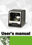
User’s Manual
OMNI-652 series
Omni-Directional Laser Scanner
Specifications subject to change without notice
Radio Notice
This equipment generates, uses and can radiate radio frequency energy. If not installed and used in
accordance with the instructions in this manual, it may cause interference to radio communications.
The equipment has been tested and found to comply with the limits for a Class A computing device
pursuant to EN55022 an 47 CFR, Part 2 and Part 15 of the FCC Rules. These specifications are
designed to provide reasonable protection against interference when operated in a commercial
environment.
Radio and Television Interference
Operation of this equipment in a residential area can cause interference to radio or television reception.
This can be determined by turning the equipment off and on. The user is encouraged to try to correct
the interference by one or more of the following measures: **Re-orient the receiving antenna.
**Relocate the device with respect to the receiver.
**Move the device away from the receiver.
**Plug the device into a different outlet so that the device and the receiver are on different
branch circuits. If necessary the user may consult the manufacturer, an authorized dealer, or
experienced radio/television technician for additional suggestions. The user may find the following
booklet prepared by the Federal Communications Commission helpful: “How to Identify and Resolve
Radio-TV Interference Problems.” This booklet is available from the U.S. Government Printing
Office, Washington, DC20402 U.S.A., Stock No. 004000003454.
For CE-countries
This scanner is in conformity with CE standards. Please note that an approved, CE-marked power
supply unit should be used in order to maintain CE conformance.
Laser Safety
The Omnidirectional Laser Scan Module complies with safety standard IEC 60825 for a Class I laser
product. It also complies with CDRH as applicable to a Class IIa laser product. Avoid long term staring
into direct laser light.
Radiant Energy: The Omnidirectional Laser Scan Module uses one low-power visible laser diode
operating at 650nm in an optomechanical scanner resulting in less than 3.9uW radiated power as
observed through a 7mm aperture and averaged over 10 seconds. Do not attempt to remove the
protective housing of the scanner, as unscanned laser light with a peak output up to 0.8mW would be
accessible inside.
Laser Light Viewing: The scan window is the only aperture through which laser light may be
observed from this product. A failure of the scanner motor, while the laser diode continues to emit a
laser beam, may cause emission levels to exceed those for safe operation. The scanner has safeguards
to prevent this occurrence, If, however, a stationary laser beam is emitted, the failing scanner should be
disconnected from its power source immediately.
Adjustments: Do not attempt any adjustments or alteration of this product. Do not remove the
protective housing of the scanner. There are no user-serviceable parts inside.
Caution: Use of controls or adjustments or performance of procedures other than those specified
herein may result in hazardous laser light exposure.
Optical: The use of optical instruments with this product will increase the eye hazard. Optical
instruments include binoculars, magnifying glasses, and microscopes but do not include normal eye
glasses worn by the user.
Table of Contents
1. General Information
2. Quick Start
2.1) Unpacking & Parts Identification
2.2) Power and Verifying Scanner Operation
2.3) Connecting to the host
3. Operation and Indicators
3.1) Operation
3.2) Indicators
4. Specifications
4.1) Controlling the Scanner from a Host System
4.2) Specifications
1. General Information
Main Features
The Omni directional Laser Scan Module is an easy-to-intergrate unit that
performs 5 directions of scan field with a 20line scan pattern cycling at 1200
scan per second for quick accurate reads. The scanner’s smart small cubic
design allows for easy integration into new equipment and efficiently reduces
overall equipment size. Multiple interfaces include keyboard wedge, USB1.1,
RS-232.
2. Quick Start
2.1) Unpacking & Parts Identification
Unpacking:
Omni-652 Unit x 1
User’s Manual x 1 (On CD)
Programming Guide x 1
5V Adaptor (optional) x 1
Parts Identification:
Scan Window
LED Indicator
Buzzer
Optical Wake-up Sensor
2.2) Power and Verifying Scanner Operation
Power:
The scanner needs a minimum of 200mA at 5V power. The power link
interface cable that comes with the scanner supports both direct power (where
the scanner takes power from the host machine) and external power (the
power adapter that’s plugged into an AC outlet). If the host machine supplies
power, it must be the same as the input power specified (200mA @ 5V). When
external power is used, the scanner does not take power from the host
machine. There is no on/off switch on the scanner. It turns on when power is
connected and turns off when power is removed. It is advised to turn off your
POS or host system before installing the scanner to avoid electronic damage
to your computer. Make sure to use only AC/DC power adaptor approved for
the scanner. The usage of other power supplies may cause damage to the
product that’s not covered by factory warranty.
Verifying Scanner Operation:
Before installing the scanner, follow the procedures below to make sure
scanning go on properly.
1. Connect the scanner with host through cable that is attached to the
scanner.
2. (If adaptor is not required, go directly to step 4) Insert the 8-pin modular
plug of the power link cable into the “host” connector in the back of the
scanner until a firm click is heard.
3. Plug the power adaptor into the jack on the power link cable.
4. When the scanner powers up, LED light up in green and the buzzer
makes four short beep sounds. When the self-test is finished the LED light
will turn red.
5. Place the "test barcode" in front of the scanner. If the scanner works right,
it will make a short beep sound, and the LED will show green light
indicating a good read, then the "test barcode" can be removed.
NOTE:
(1) If the scanner does not make any beep sounds or makes the wrong beep
sound or no LED light shows when power is connected, remove power
from scanner and refer to troubleshooting section.
(2) If the scanner is using RS-232 or keyboard wedge interface cables, it is
able to scan barcodes continuously when power is on. If the scanner is
using USB interface cable, it will only be able to scan barcodes
continuously only when connected to a host. If the scanner is not
connected to a host, it will be able to read one barcode only (LED light
stays green).
Mounting
1. Scan performance will not be affected by the mounting direction of the
scanner.
2. Use mounting holes on the bottom or/and back of the scanner to mount the
scanner onto host machine (templates at the last two pages of the manual
can be used).
Back View
Bottom View
Unit: mm (inch)
o
SR (strain release) that is connected to the cable rotates 90 to comply
with the way the scanner is mounted. Therefore the scanner will be
positioned horizontally to the host machine without cable interference for
optimal mounting. (See pictures below).
Connecting to the Host
The scanner connects to a host terminal by an interface cable. This cable
connects to the scanner with a modular connector, and connects to the host
terminal with the connector required by the host (RS-232, keyboard wedge, or
USB. Different connectors used depending on the host.) Please make sure the
right cable is used for connecting the scanner to your host terminal.
2.3) Connecting to the host
The scanner connects to a host terminal by an interface cable. This cable
connects to the scanner with a modular connector, and connects to the host
terminal with the connector required by the host (RS-232, keyboard wedge, or
USB. Different connectors used depending on the host.) Please make sure the
right cable is used for connecting the scanner to your host terminal.
Setting Up the Scanner
No set up is required if the scanner is either pre-programmed or it auto-detects
and is ready to be used. Otherwise, the scanner must be informed about the
type of system it is connected to. This can be done quickly using the
Programming Guide that’s included in the package. The Programming Guide
is used to set parameters such as communication interface type (RS-232,
Keyboard, USB), beep tone, beep volume, sleep mode timing and same-code
delay time. Set up of a parameter does not interfere with another parameter.
Scan Test
1.
With the scanner running (LED red) and the host system on, scan few
known-good barcodes.
2.
Check result on host screen. If scanner is reading correctly, no further set
up is necessary. If scanner reads incorrectly, then go to Set Up next.
Set Up
1.
With the scanner running (LED red) and the host system on, scan
<Enter/Exit Programming Mode> barcode found on the inside cover of the
Programming Guide.
2.
Scanner is ready for programming if it gives one low beep sound followed
immediately by a high beep sound and LED turns green.
3.
Find the barcode which corresponds to the parameter you require in the
Programming Guide.
4.
Scan the desired barcodes one by one as the scanner beeps once for
every barcode it memorizes.
5.
When all finished, scan <Enter/Exit Programming Mode> barcode again.
The scanner will beep twice, one long and one short. When LED turns
red, the scanner has been programmed.
6.
Test scan few known-good barcodes to make sure the scanner reads
correctly. If not, try set up procedures again.
3. Operation and Indicators
3.1) Operation
This scanner is omni-directional reading barcodes in sweep and presentation
mode depending on the host system it is attached to. Sweep mode means
moving items through the scan window (left to right, right to left, top to bottom,
bottom to top etc. are all okay). Presentation mode is when an object is moved
toward the scan window (“presented”) until the barcode is read, then the object
is removed.
3.2) Indicators
LED Indicators
LED
Status Indications
off
no power applied to the scanner
steady red light
the scanner is on and ready to
scan
one blink of
green light
one barcode has been
successfully decoded
steady green
light
*scanner is in programming
mode, *a barcode has been
successfully decoded but the
object has not been removed
from the scan window
flashing red light
scanner entering sleep mode
steady orange
light
this indicates motor failure (for
motor failure, a periodic beeping
sound will also be heard)
flashing orange
light
scanner has a laser subsystem
failure, return to repair.
Beeps
Beeps
Status Indications
one beep
a barcode has been
successfully decoded
series of 4
beeps
*scanner passed self-test
and is operating properly
*when scanner is powered
up
series of 2
beeps
when scanner is entering
programming mode
continual
beep
failure indication, return to
repair
4. Specifications
4.1) Controlling the Scanner from a Host System
The scanner can be controlled from the host system via the RS-232C interface.
Control can be accomplished by transmitting the following single-byte
commands to the scanner. The default setting for the commands are as
follows:
ASCII
Code
Function
Byte is Also
Called
OE Hex
enable (resumes disable) Shift Out or
<Ctrl-N>
OF Hex
disable
05 Hex
power-up
re-initialization
ENQ or <Ctrl-E>
12 Hex
sleep
DC2 <Ctrl-R>
14 Hex
wake up (resumes sleep)
DC4 <Ctrl-T>
Shift In or
<Ctrl-O>
Note: When the scanner is disabled, the motor of the scanner will stay on until
the scanner goes into sleep mode.
Maintaining the Scanner
The scanner rarely needs any maintenance, only an occasional cleaning of the
scanner window is necessary to remove any dirt or fingerprint. To clean the
scanner window, use a soft lint-free cloth and non-abrasive cleaner to avoid
scratching the scanner window. The scanner window can be cleaned while
the scanner is running.
4.2) Specifications
Specifications
Operational
Light source
650nm visible laser diode
Depth of Scan
0-210mm@ UPC/EAN 100%, PCS
Field
90%
Number of Scan
20
Lines
Scan Pattern
5 directions of scan field
Scan Speed
1200 scan per second
Minimum Bar
5mil @ PCS 90%
Width
Print Contrast
30% @ UPC/EAN100%
Indicators (LED)
two-color LED (red and green)
Decode
UPC/EAN/JAN, UPC Versions A&E,
Capabilities
EAN-8,
EAN-13,
JAN-8,
JAN-13,
Addendum 2 or 5, ISBN/ISSN, Japa
nese Bookland, Code 39 (with full
ASCII), Codabar (NW7), Code 128/EAN
128, Code93, Interleaved 2 of 5, MSI/
Plessey, China Post Code, Code 32
(Italian Pharmacoe)
Optional: Industrial 2 of 5, Standard 2 of
5, Discrete 2 of 5, Matrix 2 of 5, IATA
Code,
Code-11,
RSS-14,
RSS-
Expanded, RSS-Limited
Beeper
Programmable tone and beep time
Operational
System Interfaces
Keyboard, RS-232C, USB1.1, Wand
Physical
Height
120.5mm
Depth
71.35mm
Width
108.3mm
Weight
250g
Cable
Standard 2m straight
Power
Input Voltage
5VDC+10%
Power
1.0Watts
Operating Current
200mA@ 5.0V
Laser Class
CDRH Class IIa, IEC 60825-1: Class
1
EMC
CE&FCC DOC compliance
Environment
Operating
0oC-40oC
Temperature
Storage Temperature
-20oC-60oC
Humidity
5%-95% RH (non-condensing)
Light Level
max. 2500LUX (fluorescent)
Shock
Designed to withstand 1m drops
Dimensions:
Scan field:


